2008 GREAT WALL FLORID brake sensor
[x] Cancel search: brake sensorPage 23 of 281

Downloaded from www.Manualslib.com manuals search engine GWFLORID Maintenance Manual16
Air Conditioning System Structure and Parameters
ItemStructure and parameters
Structure typeVapor compression refrigeration, water warmer, and water heater
Performance parametersAir conditioner refrigerating capacity is 5 kW. Blower's air volume is 450 m3/h. Air
conditioner heating capacity is 4.5 kW.
Controls
Control panel knob, button, manual shift lever control, position gate and temperature
threshold cable drive, new damper micro-motor drive, able to select and adjust air
outlet position, heating/cooling mode, air inner/outer circulation mode and wind speed,
temperature, and more advanced selections and adjustables.
RefrigerantR134a, 510±10g
CompressorModel number: JSS-96TV4-4
CondenserAdvective and subcooling structure with flat tube thickness of 16 mm and dry reservoir
Φ34 mm × L280 mm.
Heating, Ventilating
and Air Conditioning
(HVAC)
Heating, Ventilating and Air Conditioning (HVAC): Of a three-box type consisting of
a layered evaporator, advective heater, H-shaped expansion valve, centrifugal blower,
and air outlet distributing box. Contains cooling, heating, defrosting and air freshening
functions, and operated by a link mechanism driving air valve.
Refrigeration line &
water heating tube
Refrigeration line: a compound structure using a rubber cooling pipe and an aluminum
pipe. Water heating pipe: molded rubber pipe.
SensorsEvaporator temperature sensor
Pressure switchHigh/Mid/Low three position pressure switch
Electrical System Structure and Parameters
ItemStructure and parameters
Power, start
up, and
electronic
charging
system
CircuitSingle wire system, voltage of DC12 V, negative ground
Battery12 V/60 Ah, maintenance-free battery
Starter1.2 kW
Alternator14 V/90 A
Lighting and
signaling
system
Headlight2 white (high beam 55 W, low beam 60 W) H4, height is electrically
adjustable.
Parking lamp2 front parking lamp: white, 5 W. 2 rear parking lamp: red, 5W
Turn signal lampAmber colored. 21W, 2 in the front and 21W, 2 in the back. Turn signal
lamps: 0.3W, 4 LED.
Fog lamp2 front fog lamps: 55W. 2 rear fog lamps: 7.5 W
Brake lamp2 red 21 W. high mounted brake lamps 3 W
License plate lamp2 white 5 W
Reverse lamp2 white 21 W
Hazard warning signal
lampAll turn signal lamps and switch controls
Rear reflectorsRed and non-triangular, inside the rear combination lamps.
Front reading lamp &
interior dome lamp
Front reading lamp: one white 10 W or one white 10 W, two 5 W (with
sunroof).
Interior dome lamp: White, 10 W.
Cigarette lighter
lightingBlue, 3 W, one
Page 27 of 281

Downloaded from www.Manualslib.com manuals search engine GWFLORID Maintenance Manual20
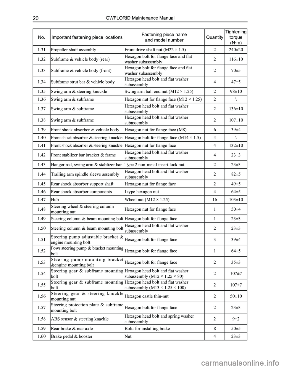
No.Important fastening piece locationsFastening piece name
and model numberQuantity
Tightening
torque
(N·m)
1.31Propeller shaft assemblyFront drive shaft nut (M22 × 1.5)2240±20
1.32Subframe & vehicle body (rear)Hexagon bolt for flange face and flat
washer subassembly2116±10
1.33Subframe & vehicle body (front)Hexagon bolt for flange face and flat
washer subassembly270±5
1.34Subframe strut bar & vehicle bodyHexagon head bolt and flat washer
subassembly447±5
1.35Swing arm & steering knuckleSwing arm ball end nut (M12 × 1.25)298±10
1.36Swing arm & subframeHexagon nut for flange face (M12 × 1.25)2\
1.37Swing arm & subframeHexagon head bolt and flat washer
subassembly2136±10
1.38Swing arm & subframeHexagon head bolt and flat washer
subassembly2107±10
1.39Front shock absorber & vehicle bodyHexagon nut for flange face (M8)639±4
1.40Front shock absorber & steering knuckleHexagon bolt for flange face (M14 × 1.5)4\
1.41Front shock absorber & steering knuckleHexagon nut for flange face4132±10
1.42Front stablizer bar bracket & frameHexagon head bolt and flat washer
subassembly423±3
1.43Hanger rod, swing arm & stablizer barType 2 non-metal insert lock nut223±3
1.44Trailing arm spindle sleeve assemblyHexagon head bolt and flat washer
subassembly282±5
1.45Rear shock absorber support shaftHexagon nut for flange face249±5
1.46Rear shock absorber componentsI type hexagon nut464±5
1.47Hub Wheel nut (M12 × 1.25)16103±10
1.48Steering wheel & steering column
mounting nutHexagon nut for flange face150±4
1.49Steering column & beam mounting boltHexagon bolt for flange face123±3
1.50Steering column & beam mounting boltHexagon head bolt and flat washer
subassembly223±3
1.51Steering pump adjustable bracket &
engine mounting boltHexagon bolt for flange face339±4
1.52Powr steering pump & bracket mounting
boltHexagon bolt for flange face164±5
1.53S t e e r i n g p u m p m o u n t i n g b r a c k e t
&engine mounting boltHexagon bolt for flange face235±3
1.54Steering gear & subframe mounting
bolt
Hexagon head bolt and flat washer
subassembly (M12 × 1.25 × 80)2107±7
1.55Steering gear & subframe mounting
bolt
Hexagon head bolt and flat washer
subassembly (M13 × 1.25 × 100)2107±7
1.56S t e e r i n g g e a r & s t e e r i n g k n u c k l e
mounting nutHexagon castle thin-nut250±10
1.57Steering protection plate & subframe
mounting boltHexagon bolt for flange face223±3
1.58ABS sensor & steering knackleHexagon head bolt and spring washer
subassembly29±2
1.59Rear brake & rear axleBolt: for installing brake850±5
1.60Brake pedal & boosterNut423±3
Page 28 of 281

Downloaded from www.Manualslib.com manuals search engine 21Overall Parameters
No.Important fastening piece locationsFastening piece name
and model numberQuantity
Tightening
torque
(N·m)
1.61ABS sensor front wire harness & front
shock absorber
Hexagon head bolt and flat washer
subassembly223±3
1.62ABS & vehicle body Hexagon head bolt and flat washer
subassembly323±2
1.63Parking brake cable & vehicle bodyH e x a g o n h e a d b o l t a n d s p r i n g w a s h e r
subassembly69±2
1.64Parking brake cable & rear brakeH e x a g o n h e a d b o l t a n d s p r i n g w a s h e r
subassembly29±2
1.65ABS sensor rear wire harness, vehicle
body & rear brake
H e x a g o n h e a d b o l t a n d s p r i n g w a s h e r
subassembly69±2
1.66Parking brake fixed cable braket &
vehicle body
H e x a g o n h e a d b o l t a n d s p r i n g w a s h e r
subassembly19±2
1.67ABS sensor front wire harness & vehicle
body
Hexagon head bolt, spring washer and flat
washer subassembly29±2
1.68Parking brake control mechanismHexagon head bolt, spring washer and flat
washer subassembly223±3
1.69Rear brake pipe connector & vehicle
bodyHexagon bolt for flange face19±2
1.70Seven-hole tube clamp & vehicle bodyHexagon bolt for flange face19±2
1.71Brake pedal & vehicle bodyHexagon bolt for flange face123±3
1.72Brake cable & rear axleHexagon nut for flange face29±2
1.73All of the brake line connectors M1016±2
1.74All of the brake line connectors M1216±2
2Vehicle body
2.1Connected seat belt Front seat belt upper mounting bolt (7/16.)242±5
2.2Connected seat belt Seat belt lower mounting bolt (7/16.)438±5
2.3Connected seat belt retractorFront seat belt retractor lower bolt (7/16.)238±5
2.4Connected seat belt retractorHexagon bolt for flange face29±3
2.5Connected seat belt Rear seat belt upper mounting bolt (7/16.)238±5
2.6Connected seat belt retractorRear seat belt retractor bolt (7/16.)238±5
2.7Connected seat belt Mounting bolts on the middle seat belt
(7/16.)138±5
2.8Connected front seat belt mortise lockFront seat belt mortise lock bolt (7/16.)260±5
2.9Connected rear seat belt lockRear seat belt lock bolt (7/16.)238±5
3Air conditioner
3.1Compressor bracket & engineHexagon bolt for flange face Q1841030FD
(M10 × 1.25)464±5
3.2Comperssor bracket & compressorHexagon bolt for flange face-oversize
Q1860890FD423±3
3.3Condensor fan mounting boltHexagon head bolt and flat washer
subassembly Q1400630 (Q402) F3219±2
3.4Condensor mounting boltHexagon bolt for flange face223±3
3.5Compressor suction hose & HVAC
refrigeration line portHexagon bolt for flange face Q1460640F3219±2
3.6Air conditioner hose, compressor, and
condenser coupling boltHexagon bolt for flange face Q1840625F3249±2
3.7Expansion valve & HVAC refrigeration line portHexagon bolt for flange face Q1840630F3229±2
Page 81 of 281

Downloaded from www.Manualslib.com manuals search engine GWFLORID Maintenance Manual74
3. Remove the wheel speed sensor and the brake hose
Remove the wheel speed sensor's mounting bolts with a M10
sleeve to take off the wheel speed sensor. Remove the front
brake hose's mounting bolts with a M18 sleeve, and then
take off the brake hose.
Caution: When removing the brake hose, brake fluid
may flow out, catch the fluid with a container. Also,
b e c a u s e t h e b r a k e f l u i d i s c o r r o s i v e , p l e a s e p a y
attention to personal protection.
4. Remove the cotter pins and lock nuts of the steering tie
rod and the lower swing arm
Because the ball stud and steering knuckle act in conjunction
with the tapered bore, they can not yet be removed after re-
moving the nuts. Pound the steering knuckle arm (unfinished
surface) with a hammer. Positions are shown on the left.
Shake to loosen.
Caution:
1. To avoid separating the ball studs, do not pound the
tie rod and the lower swing arm with a hammer.
2. To avoid damaging the thread, do not hammer the
ball stud's head.
Front brake hose mounting bolt
Wheel speed sensor mounting bolts
Lightly hammer here
Page 82 of 281

Downloaded from www.Manualslib.com manuals search engine 75Suspension System
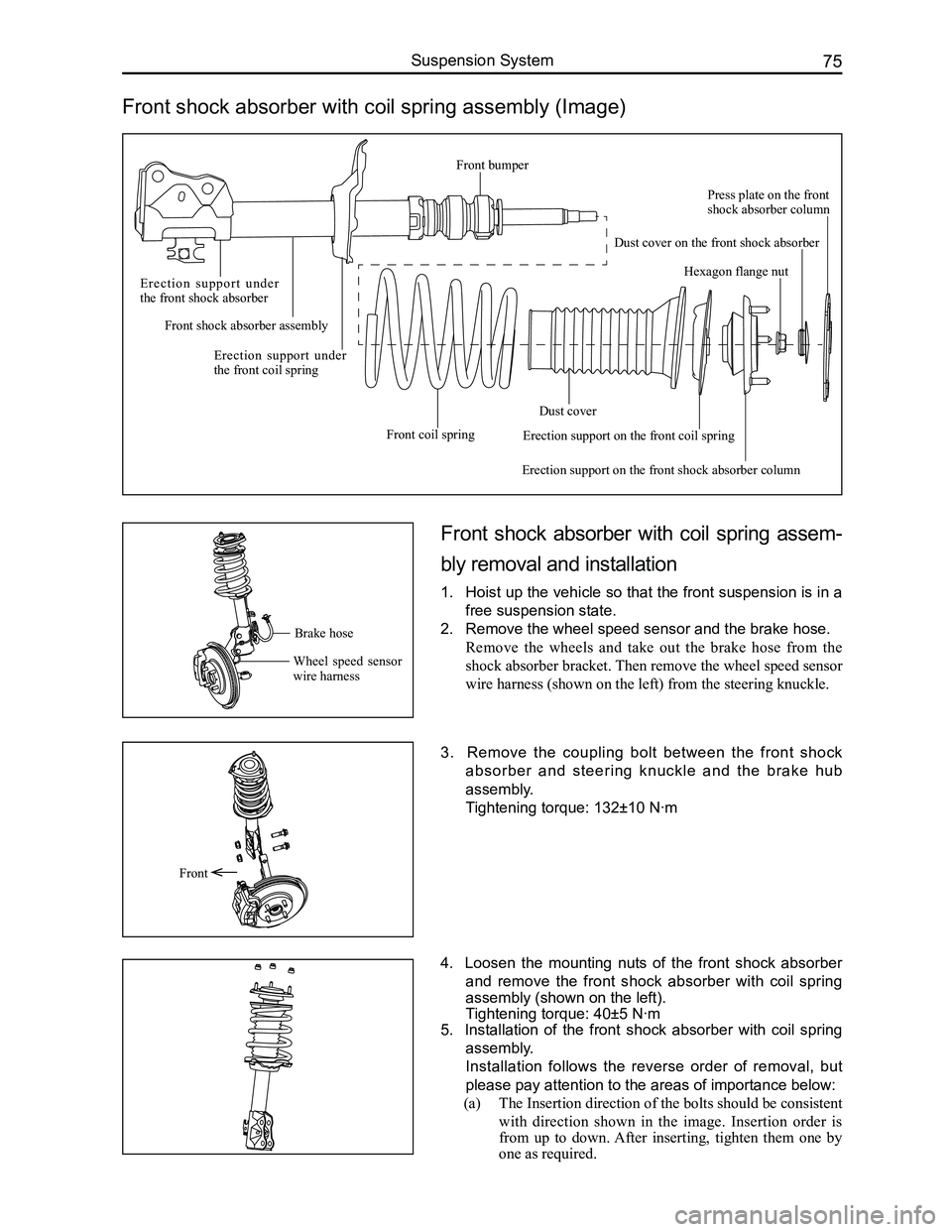
Front shock absorber with coil spring assembly (Image)
Front shock absorber with coil spring assem-
bly removal and installation
1. Hoist up the vehicle so that the front suspension is in a
free suspension state.
2. Remove the wheel speed sensor and the brake hose.
Remove the wheels and take out the brake hose from the
shock absorber bracket. Then remove the wheel speed sensor
wire harness (shown on the left) from the steering knuckle.
3. Remove the coupling bolt between the front shock
absorber and steering knuckle and the brake hub
assembly.
Tightening torque: 132±10 N·m
4. Loosen the mounting nuts of the front shock absorber
and remove the front shock absorber with coil spring
assembly (shown on the left).
Tightening torque: 40±5 N·m
5. Installation of the front shock absorber with coil spring
assembly.
Installation follows the reverse order of removal, but
please pay attention to the areas of importance below:
(a) The Insertion direction of the bolts should be consistent
with direction shown in the image. Insertion order is
from up to down. After inserting, tighten them one by
one as required.
Front
Brake hose
Wheel speed sensor wire harness
E r e c t i o n s u p p o r t u n d e r the front shock absorber
Front shock absorber assembly
Erection support under the front coil spring
Front coil spring
Dust cover
Erection support on the front shock absorber column
Hexagon flange nut
Press plate on the front shock absorber column
Dust cover on the front shock absorber
Erection support on the front coil spring
Front bumper
Page 102 of 281

Downloaded from www.Manualslib.com manuals search engine 95Brake System
Brake System Components Arrangement Schematics
Brake pedal assembly
Vacuum booster with brake cylinder assembly
Left steering knuckle and hub brake assembly
Left parking brake cable assembly
Rear brake assembly RHRear brake drum
Rear wheel speed sensor assembly RH
Right parking brake cable assembly
ABS controller assembly
Right steering knuckle and hub brake assembly
Brake line assembly
Rear wheel speed
sensor assembly LH
Front wheel speed sensor assembly RHFront wheel speed sensor assembly LH
Rear brake assembly LH
Parking brake control mechanism assembly
Page 114 of 281

Downloaded from www.Manualslib.com manuals search engine 107Brake System
Anti-lock Brake System
ABS/EBD introduction
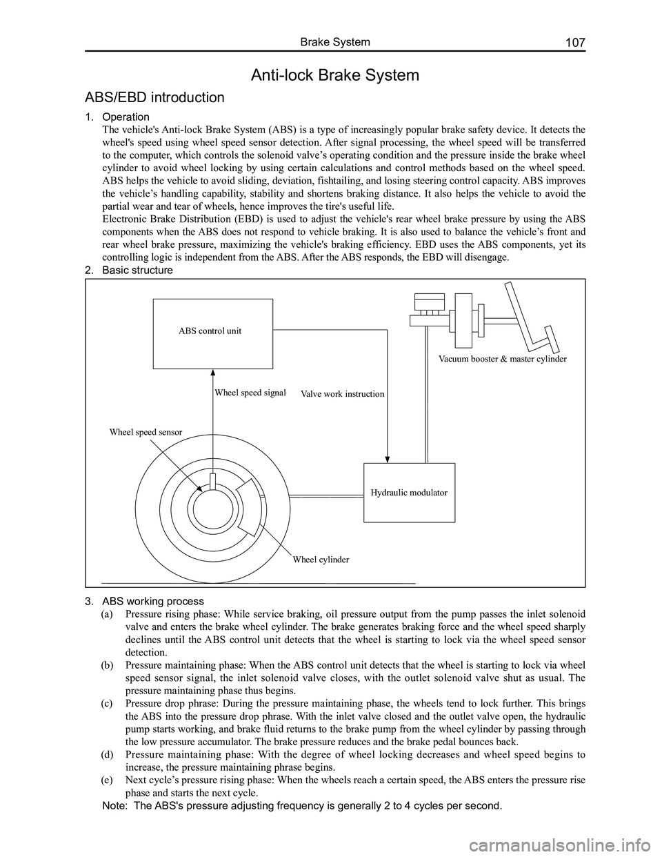
1. Operation
The vehicle's Anti-lock Brake System (ABS) is a type of increasingly popular brake safety device. It detects the
wheel's speed using wheel speed sensor detection. After signal processing, the wheel speed will be transferred
to the computer, which controls the solenoid valve’s operating condition and the pressure inside the brake wheel
cylinder to avoid wheel locking by using certain calculations and control methods based on the wheel speed.
ABS helps the vehicle to avoid sliding, deviation, fishtailing, and losing steering control capacity. ABS improves
the vehicle’s handling capability, stability and shortens braking distance. It also helps the vehicle to avoid the
partial wear and tear of wheels, hence improves the tire's useful life.
Electronic Brake Distribution (EBD) is used to adjust the vehicle's rear wheel brake pressure by using the ABS
components when the ABS does not respond to vehicle braking. It is also used to balance the vehicle’s front and
rear wheel brake pressure, maximizing the vehicle's braking efficiency. EBD uses the ABS components, yet its
controlling logic is independent from the ABS. After the ABS responds, the EBD will disengage.
2. Basic structure
3. ABS working process
(a) Pressure rising phase: While service braking, oil pressure output from the pump passes the inlet solenoid
valve and enters the brake wheel cylinder. The brake generates braking force and the wheel speed sharply
declines until the ABS control unit detects that the wheel is starting to lock via the wheel speed sensor
detection.
(b) Pressure maintaining phase: When the ABS control unit detects that the wheel is starting to lock via wheel
speed sensor signal, the inlet solenoid valve closes, with the outlet solenoid valve shut as usual. The
pressure maintaining phase thus begins.
(c) Pressure drop phrase: During the pressure maintaining phase, the wheels tend to lock further. This brings
the ABS into the pressure drop phrase. With the inlet valve closed and the outlet valve open, the hydraulic
pump starts working, and brake fluid returns to the brake pump from the wheel cylinder by passing through
the low pressure accumulator. The brake pressure reduces and the brake pedal bounces back.
(d) Pressure maintaining phase: With the degree of wheel locking decreases and wheel speed begins to
increase, the pressure maintaining phrase begins.
(e) Next cycle’s pressure rising phase: When the wheels reach a certain speed, the ABS enters the pressure rise
phase and starts the next cycle.
Note: The ABS's pressure adjusting frequency is generally 2 to 4 cycles per second.
ABS control unit
Wheel speed sensor
Wheel speed signal
Wheel cylinder
Valve work instruction
Hydraulic modulator
Vacuum booster & master cylinder
Page 115 of 281

Downloaded from www.Manualslib.com manuals search engine GWFLORID Maintenance Manual108
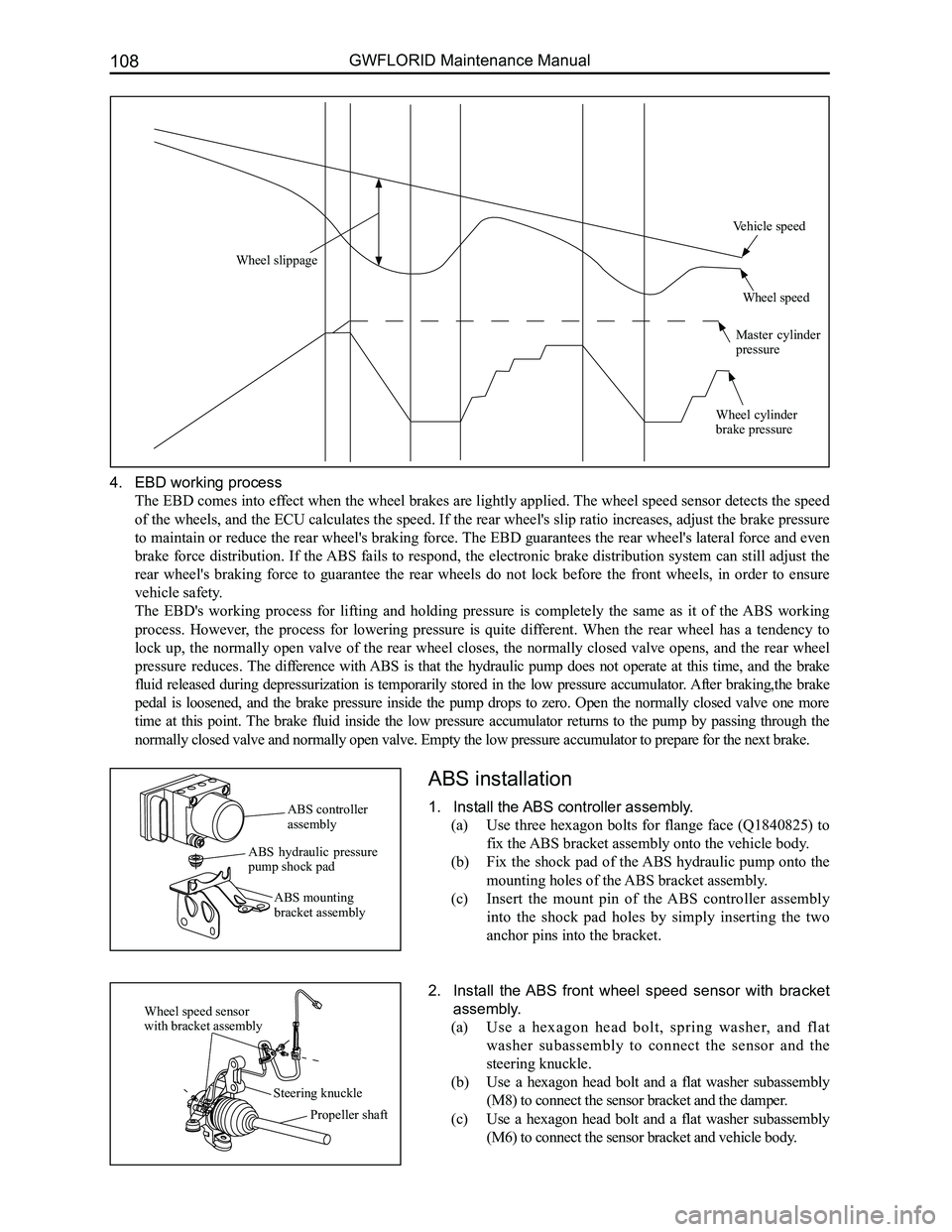
4. EBD working process
The EBD comes into effect when the wheel brakes are lightly applied. The wheel speed sensor detects the speed
of the wheels, and the ECU calculates the speed. If the rear wheel's slip ratio increases, adjust the brake pressure
to maintain or reduce the rear wheel's braking force. The EBD guarantees the rear wheel's lateral force and even
brake force distribution. If the ABS fails to respond, the electronic brake distribution system can still adjust the
rear wheel's braking force to guarantee the rear wheels do not lock before the front wheels, in order to ensure
vehicle safety.
The EBD's working process for lifting and holding pressure is completely the same as it of the ABS working
process. However, the process for lowering pressure is quite different. When the rear wheel has a tendency to
lock up, the normally open valve of the rear wheel closes, the normally closed valve opens, and the rear wheel
pressure reduces. The difference with ABS is that the hydraulic pump does not operate at this time, and the brake
fluid released during depressurization is temporarily stored in the low pressure accumulator. After braking,the brake
pedal is loosened, and the brake pressure inside the pump drops to zero. Open the normally closed valve one more
time at this point. The brake fluid inside the low pressure accumulator returns to the pump by passing through the
normally closed valve and normally open valve. Empty the low pressure ac\
cumulator to prepare for the next brake.
ABS installation
1. Install the ABS controller assembly.
(a) Use three hexagon bolts for flange face (Q1840825) to
fix the ABS bracket assembly onto the vehicle body.
(b) Fix the shock pad of the ABS hydraulic pump onto the
mounting holes of the ABS bracket assembly.
(c) Insert the mount pin of the ABS controller assembly
into the shock pad holes by simply inserting the two
anchor pins into the bracket.
2. Install the ABS front wheel speed sensor with bracket
assembly.
(a) Use a hexagon head bolt, spring washer, and flat
washer subassembly to connect the sensor and the
steering knuckle.
(b) Use a hexagon head bolt and a flat washer subassembly
(M8) to connect the sensor bracket and the damper.
(c) Use a hexagon head bolt and a flat washer subassembly
(M6) to connect the sensor bracket and vehicle body.
ABS controller assembly
ABS hydraulic pressure pump shock pad
ABS mounting bracket assembly
Wheel speed sensor with bracket assembly
Steering knuckle
Propeller shaft
Wheel slippage
Vehicle speed
Wheel speed
Master cylinder pressure
Wheel cylinder brake pressure