2008 GREAT WALL FLORID wheel
[x] Cancel search: wheelPage 100 of 281

Downloaded from www.Manualslib.com manuals search engine 93Suspension System
Dynamic balance and static balance
There are two types of wheel balance: static and dynamic.
Picture 1 shows static balance. Picture 2 shows dynamic
balance.
Static balance means that the weight distribution around the
wheel is equal. If the wheel is static and unbalanced, violent
vibrations may be created, called jump vibration.This kind
of situation can ultimately lead to the uneven wear and tear
of the tires. Shown in diagram 1.
Dynamic balance means that the weight distribution on the
two sides of the medium plane of the wheel is equal, so
during the rotation process, the tire assembly cannot create a
tendency for the medium plane of the wheel to shift from one
side to the other. If the wheel is dynamic and unbalanced, it
can create a shimmying effect. Shown in diagram 2.
1. Wheel shimmy important points[C]: Counterweight not yet added
2. Locations to add counterweight[D]: Counterweight added
3. Axis
Wheel maintenance
Do not use welding, heating, or hammering to repair wheels. All damaged wheels must be replaced.
If the vehicle's wheel is twisted or deformed, sunken or depressed, having too much horizontal or radial hop,
leaking air from the welded parts, stretched out at the bolt holes , having flimsy nut bolt lock, or severely rusty,
the wheel must be replaced. When the wheel is hopping too much, it will lead to undesirable vibratio\
ns.
When replacing the tire, be sure that the load capacity, diameter, rim width, offset distance, and the installation
structure of it, are equal to the settings of original wheel. If the wheel dimensions are not appropriate, this will
influence the wheel and bearing's life, brake cooling effect, speedometer and odometer calibration, vehicle
ground clearance, as well as the clearance between the tire and the vehi\
cle body, and the tire and vehicle chassis.
Wheel (steel wheel) removal
1. Remove the wheelhouse and loosen the nuts, 1-2 turns is
enough.
2. Hoist the vehicle.
3. Screw off the nuts and remove the wheel.
Nut tightening torque: 110±10 N·m
Caution: Heating methods absolutely must not be used
to loosen tightened wheels, otherwise the heat will
reduce its use life and damage the hub bearing.
Wheel (steel wheel) installation
Installation according to the reversed instructions used for
removal, and pay attention to the following requirements:
Wheel nuts must be tightened in proper order and according to
the specified torque, as to avoid wheel or brake disc deformity.
When installing the wheel house, be sure to line up the wheel
housing notch locations with the inflation nozzle.
Tightening sequence: A – C – B – D
Caution: Before installing the wheel, first clean off the
corrosion on the wheel's mounting surface and drum
brake or brake disc's installation surface with a wire
brush, in order to make the wheel installing easier by
making the space between its metal firmly connect
to the mounting surface, otherwise it may lead to the
wheel nuts loosening to the extent that the vehicle's
wheel may come off while driving some day.
1
3
2[A][B]
1. Wheel hop important points[A]: Counterweight not yet added
2. Locations to add counterweight[B]: Counterweight added
3. Axis
Diagram 1
Diagram 2
[C][D]
1
3
2
AB
CD
Page 102 of 281

Downloaded from www.Manualslib.com manuals search engine 95Brake System
Brake System Components Arrangement Schematics
Brake pedal assembly
Vacuum booster with brake cylinder assembly
Left steering knuckle and hub brake assembly
Left parking brake cable assembly
Rear brake assembly RHRear brake drum
Rear wheel speed sensor assembly RH
Right parking brake cable assembly
ABS controller assembly
Right steering knuckle and hub brake assembly
Brake line assembly
Rear wheel speed
sensor assembly LH
Front wheel speed sensor assembly RHFront wheel speed sensor assembly LH
Rear brake assembly LH
Parking brake control mechanism assembly
Page 103 of 281

Downloaded from www.Manualslib.com manuals search engine GWFLORID Maintenance Manual96
Brake System Maintenance
Brake fluid inspection and replacement
Brake fluid directly influences the brake performance and the operating conditions and use life of the brake
system components. Brake fluid has very strong hygroscopic properties, and thus absorbs water easily,
which will then deteriorate the metal and rubber pieces. Polluted and deteriorated brake fluid or its mixture
would cause the brake fluid to boil and gasify, hence reduces braking efficiency. Therefore, pay attention to
the items below when filling or changing the brake fluid:
1. Containers used to hold brake fluid must be tightly closed and sealed
2. Brake fluid is poisonous and damaging to the paint. Hence if it gets on the vehicle surface, rub it
off at once
3. If water or other contaminates found in the brake fluid, and the brake master cylinder's piston seal
has been broken, then the brake fluid and all the rubber pieces inside the brake system including
the brake hose must be replaced
4. The correct brake fluid level in the reservoir must be between MAX and MIN. After the vehicle has
been driven for over 1000 km, check the brake fluid level in the reservoir. If the brake fluid level is
not up to regulation, more brake fluid should be added to the reservoir \
until it reaches MAX.
Hydraulic component inspection and system flushing
1. If the oil-based solvent gets into the hydraulic system, flush the whole system and change all of
the rubber pieces
2. Clean your hands before installing new rubber pieces or other components
3. Do not use regular solvents (kerosene, gas, etc.) when inspecting or cleaning hydraulic
components, instead use absorbing alcohol or brake fluid
4. After inspecting the components, drain the brake fluid from the system. Use new brake fluid to
flush the system. Afterwards, add new brake fluid to perform hydraulic system exhaust
5. Flushing completion sign: When the brake fluid flowing out of the dump valve is clear from any
contaminate.
Hydraulic pressure system drainage
If the brake fluid inside the whole hydraulic pressure system needs to be emptied, open all the bleed screws
with each connected to a hose, as to allow the brake fluid to flow into a container. Step on the pedal slowly
until only air flows out. During the whole procedure, make sure all the \
valves are open.
Hydraulic pressure system air bleeding
The hydraulic brake system must work under a vacuum environment. The air will cause spongy brake or
overall brake failure when it flows into the hydraulic system. It is extremely necessary to bleed system air
when performing any operation on the brake system or if any air inside t\
he brake system is suspected.
1. Air bleeding sequence
If air inside the brake master cylinder is suspected, first perform air bleeding.
(a) If numerous valves are equipped, air bleed each valve
(b) Another sequence principle is: Air bleed from the wheel brake furthest away from the master cylinder.
The air bleeding sequence for the LHD modules is: rear right wheel - left rear wheel - front right wheel
- front left wheel, Right rudder vehicles: rear right wheel - left rear wheel - front left wheel - front right
wheel.
2. Air bleeding method
(1) Manual air bleeding
Use the brake pedal or pump as the air bleeding power source. When the air bleed screws are open, vent the
brake fluid containing the bubbles from the system. Usually this is simultaneously done by two people. One
steps on the brake pedal and the other operates the air bleed screws. Important points to take note of when
performing the operation:
(a) Place the ignition switch to the off position and step on the pedal repeatedly to remove the
vacuum pressure or hydraulic pressure.
(b) Before and after air bleeding, add clean brake fluid into the master cylinder until it reaches
the correct (stated) level.
(c) Check the fluid level frequently to make sure that more than half of the reservoir's capacity is
available.
(d) Bleed screws should only be opened when the pedal is pressed down, and closed before the
pedal is loosened. Meanwhile, check if the vented brake fluid has bubble\
s inside.
Page 104 of 281

Downloaded from www.Manualslib.com manuals search engine 97Brake System
(e) Make sure not to let the system valves block the air bleeding.
(f) When the brake fluid that flows out of the hose or connector has no bubbles, it means that the air
in the system has been exhausted. There is still air inside the system if the hose inserted into the
brake fluid is still bubbling when pressing down the pedal.
(g) Keep the free end of the hose immerged in the brake fluid to avoid air from flowing into the
system while opening the screw.
(h) While air bleeding, hammer the casting part of the vibrating brake device with a rubber hammer.
This is helpful for removing bubbles deep in the brake fluid.
(i) If air in the master cylinder is suspected, then perform air bleeding on the master cylinder first,
then the wheel cylinder or brake caliper.
(j) When releasing air from the tires, generally make sure to release air out of all the tires.
(k) To avoid the possibility of air reversely entering into the system, a bleeder hose that has a check
valve could be used.
(2) Pressure blow-off
Under the proper conditions, a pressure blow-off device can be used to release the air inside the brake system.
3. Air releasing sequence
(1) Master cylinder air bleeding
If the master cylinder does not have air bleed screws, perform the follo\
wing steps:
(a) Check the brake fluid level inside the master cylinder’s reservoir and add to it if necessary.
(b) Slowly take off the front brake pipe connector until the brake fluid flows out from the end.
(c) Reconnect the brake pipe, but do not tighten it.
(d) Slowly step down and press on the brake pedal, check if the brake fluid flowing out of the connector
contains bubbles.
(e) Tighten the pipe fitting.
(f) Have the assistant loosen the pedal, wait for 15 s.
(g) Repeat the above steps until all the air is released.
(h) Take off the rear brake pipe connector, repeat the above steps.
(2) Wheel brake air releasing
(a) Check the brake fluid level inside the master cylinder’s reservoir and add to it if necessary. During the
entire air releasing period, check repeatedly and add promptly.
(b) Connect one end of the bleeder hose with the bleed screw and the other end immerged in the brake fluid.
(c) Have the assistant step on the pedal several times, raise the pedal gradually until it cannot be stepped on
any more, then forcibly press on the pedal once more.
(d) Loosen the bleed screw, check if there are any bubbles in the brake fluid flowing out. Meanwhile, slowly
lower the pedal.
(e) When the brake pedal is close to the stroke end or the out flowing brake fluid does not have any bubbles,
tighten the bleed screw.
(f) Have the assistant release the pedal and wait for 15 s.
(g) Repeat the above steps until there are no bubbles in the flowing brake fluid when the screw is loosened.
(h) Release the air for all the wheels in turn using the same method.
(i) After releasing the air from the entire system, switch the ignition to the on position.
(j) Inspect the stroke of the brake pedal and its reaction.
(k) Inspect the lighting condition of the brake warning lamp, and repeatedly perform maintenance or air
bleeding if necessary.
( l ) Add brake fluid to the reservoir until the specified fluid level, air bleeding is complete.
Page 114 of 281

Downloaded from www.Manualslib.com manuals search engine 107Brake System
Anti-lock Brake System
ABS/EBD introduction
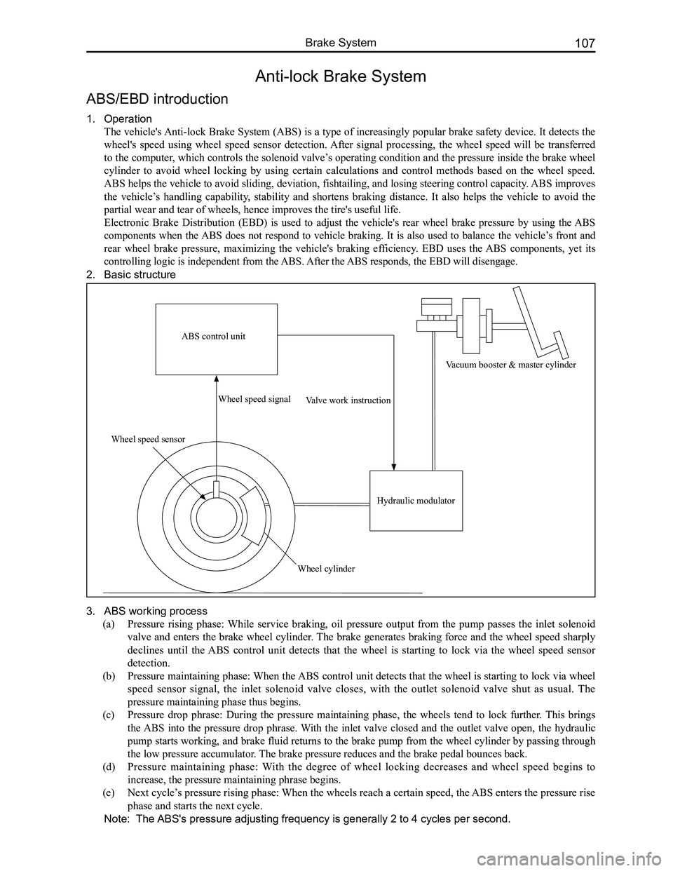
1. Operation
The vehicle's Anti-lock Brake System (ABS) is a type of increasingly popular brake safety device. It detects the
wheel's speed using wheel speed sensor detection. After signal processing, the wheel speed will be transferred
to the computer, which controls the solenoid valve’s operating condition and the pressure inside the brake wheel
cylinder to avoid wheel locking by using certain calculations and control methods based on the wheel speed.
ABS helps the vehicle to avoid sliding, deviation, fishtailing, and losing steering control capacity. ABS improves
the vehicle’s handling capability, stability and shortens braking distance. It also helps the vehicle to avoid the
partial wear and tear of wheels, hence improves the tire's useful life.
Electronic Brake Distribution (EBD) is used to adjust the vehicle's rear wheel brake pressure by using the ABS
components when the ABS does not respond to vehicle braking. It is also used to balance the vehicle’s front and
rear wheel brake pressure, maximizing the vehicle's braking efficiency. EBD uses the ABS components, yet its
controlling logic is independent from the ABS. After the ABS responds, the EBD will disengage.
2. Basic structure
3. ABS working process
(a) Pressure rising phase: While service braking, oil pressure output from the pump passes the inlet solenoid
valve and enters the brake wheel cylinder. The brake generates braking force and the wheel speed sharply
declines until the ABS control unit detects that the wheel is starting to lock via the wheel speed sensor
detection.
(b) Pressure maintaining phase: When the ABS control unit detects that the wheel is starting to lock via wheel
speed sensor signal, the inlet solenoid valve closes, with the outlet solenoid valve shut as usual. The
pressure maintaining phase thus begins.
(c) Pressure drop phrase: During the pressure maintaining phase, the wheels tend to lock further. This brings
the ABS into the pressure drop phrase. With the inlet valve closed and the outlet valve open, the hydraulic
pump starts working, and brake fluid returns to the brake pump from the wheel cylinder by passing through
the low pressure accumulator. The brake pressure reduces and the brake pedal bounces back.
(d) Pressure maintaining phase: With the degree of wheel locking decreases and wheel speed begins to
increase, the pressure maintaining phrase begins.
(e) Next cycle’s pressure rising phase: When the wheels reach a certain speed, the ABS enters the pressure rise
phase and starts the next cycle.
Note: The ABS's pressure adjusting frequency is generally 2 to 4 cycles per second.
ABS control unit
Wheel speed sensor
Wheel speed signal
Wheel cylinder
Valve work instruction
Hydraulic modulator
Vacuum booster & master cylinder
Page 115 of 281

Downloaded from www.Manualslib.com manuals search engine GWFLORID Maintenance Manual108
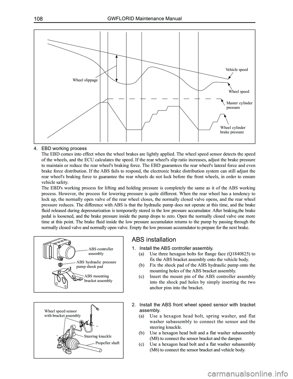
4. EBD working process
The EBD comes into effect when the wheel brakes are lightly applied. The wheel speed sensor detects the speed
of the wheels, and the ECU calculates the speed. If the rear wheel's slip ratio increases, adjust the brake pressure
to maintain or reduce the rear wheel's braking force. The EBD guarantees the rear wheel's lateral force and even
brake force distribution. If the ABS fails to respond, the electronic brake distribution system can still adjust the
rear wheel's braking force to guarantee the rear wheels do not lock before the front wheels, in order to ensure
vehicle safety.
The EBD's working process for lifting and holding pressure is completely the same as it of the ABS working
process. However, the process for lowering pressure is quite different. When the rear wheel has a tendency to
lock up, the normally open valve of the rear wheel closes, the normally closed valve opens, and the rear wheel
pressure reduces. The difference with ABS is that the hydraulic pump does not operate at this time, and the brake
fluid released during depressurization is temporarily stored in the low pressure accumulator. After braking,the brake
pedal is loosened, and the brake pressure inside the pump drops to zero. Open the normally closed valve one more
time at this point. The brake fluid inside the low pressure accumulator returns to the pump by passing through the
normally closed valve and normally open valve. Empty the low pressure ac\
cumulator to prepare for the next brake.
ABS installation
1. Install the ABS controller assembly.
(a) Use three hexagon bolts for flange face (Q1840825) to
fix the ABS bracket assembly onto the vehicle body.
(b) Fix the shock pad of the ABS hydraulic pump onto the
mounting holes of the ABS bracket assembly.
(c) Insert the mount pin of the ABS controller assembly
into the shock pad holes by simply inserting the two
anchor pins into the bracket.
2. Install the ABS front wheel speed sensor with bracket
assembly.
(a) Use a hexagon head bolt, spring washer, and flat
washer subassembly to connect the sensor and the
steering knuckle.
(b) Use a hexagon head bolt and a flat washer subassembly
(M8) to connect the sensor bracket and the damper.
(c) Use a hexagon head bolt and a flat washer subassembly
(M6) to connect the sensor bracket and vehicle body.
ABS controller assembly
ABS hydraulic pressure pump shock pad
ABS mounting bracket assembly
Wheel speed sensor with bracket assembly
Steering knuckle
Propeller shaft
Wheel slippage
Vehicle speed
Wheel speed
Master cylinder pressure
Wheel cylinder brake pressure
Page 116 of 281

Downloaded from www.Manualslib.com manuals search engine 109Brake System
3. Installing the ABS rear wheel speed sensor with brack-
et assembly.
Use three hexagon head bolts, spring washers, and flat
washer subassembly connecting pieces to connect the sensor
to the rear hub unit, rear twist beam, and vehicle body.
ABS General Problem Maintenance and Areas of Importance
Common problems and solutions
1. When braking, the ABS hydraulic pressure unit noise is overly loud.
When the ABS is working, the motor inside the hydraulic pressure unit is ceaselessly rotating. At this time the
driver can feel the brake pedal bouncing back. However, this bounce back feeling will be entirely different
depending on the speed and road condition. Also, when performing an actuator movement test, the sound of the
running motor may also be sensed. When the vehicle is being driven and the brake is off, the sound of the motor
running can still occasionally be heard. This is the ABS undergoing component inspection, not a malfunction.
If the ABS hydraulic pressure unit noise is irregular, a movement test can be initiated. Compare the noise to that
of normal vehicles to determine if ABS hydraulic pressure unit noise is abnormal.
2. Inlet and outlet solenoid valve failure.
Once the ignition switch is ON, the ABS control unit automatically initiates a self-check. If an inlet and outlet solenoid
valve short circuit or open circuit is found, it will record the failure, light up the fault light, and abort the operation. If using a
scanner to adjust the problem code, make sure to use the movement test t\
o confirm that the solenoid valve has a problem and
then replace the hydraulic pressure unit directly.
X431 data flow: While the ABS is functioning, the inlet and outlet solenoid valves rapidly change operating
conditions.
EVFL - Front inlet valve LHOff / On
AVFL - Front outlet valve LHOff / On
EVFR - Front outlet valve RHOff / On
AVFR - Rront outlet valve RHOff / On
EVRR - Rear inlet valve LHOff / On
AVRR - Rear outlet valve LHOff / On
EVRR - Rear inlet valve RHOff / On
AVRR - Rear outlet valve RHOff / On
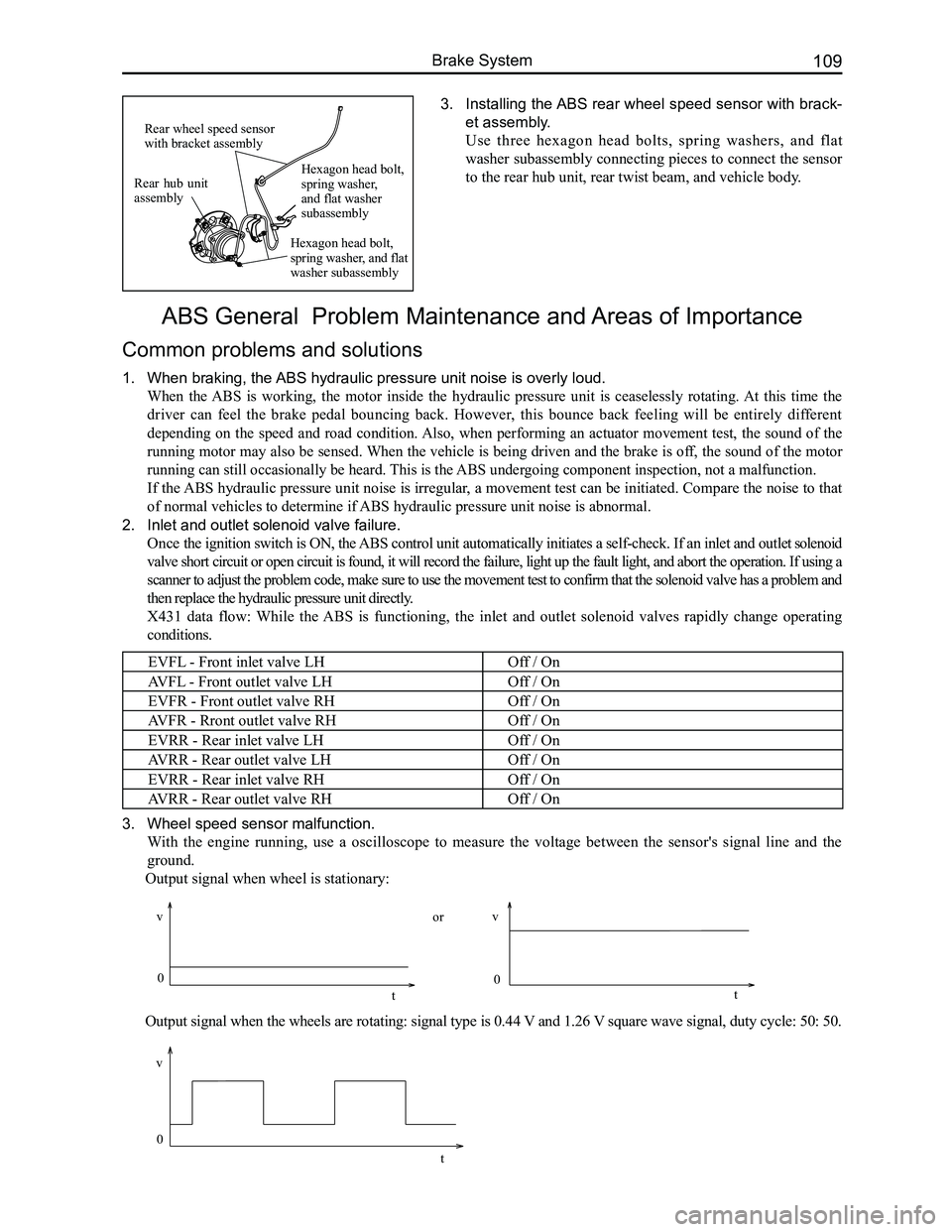
3. Wheel speed sensor malfunction.
With the engine running, use a oscilloscope to measure the voltage between the sensor's signal line and the
ground.
Output signal when wheel is stationary:
Output signal when the wheels are rotating: signal type is 0.44 V and 1.26 V square wave signal, duty cycle: 50: 50.
Rear hub unit assembly
Rear wheel speed sensor with bracket assembly
Hexagon head bolt, spring washer, and flat washer subassembly
Hexagon head bolt, spring washer, and flat washer subassembly
0
v
t
vv
0 0
tt
or
Page 117 of 281

Downloaded from www.Manualslib.com manuals search engine GWFLORID Maintenance Manual110
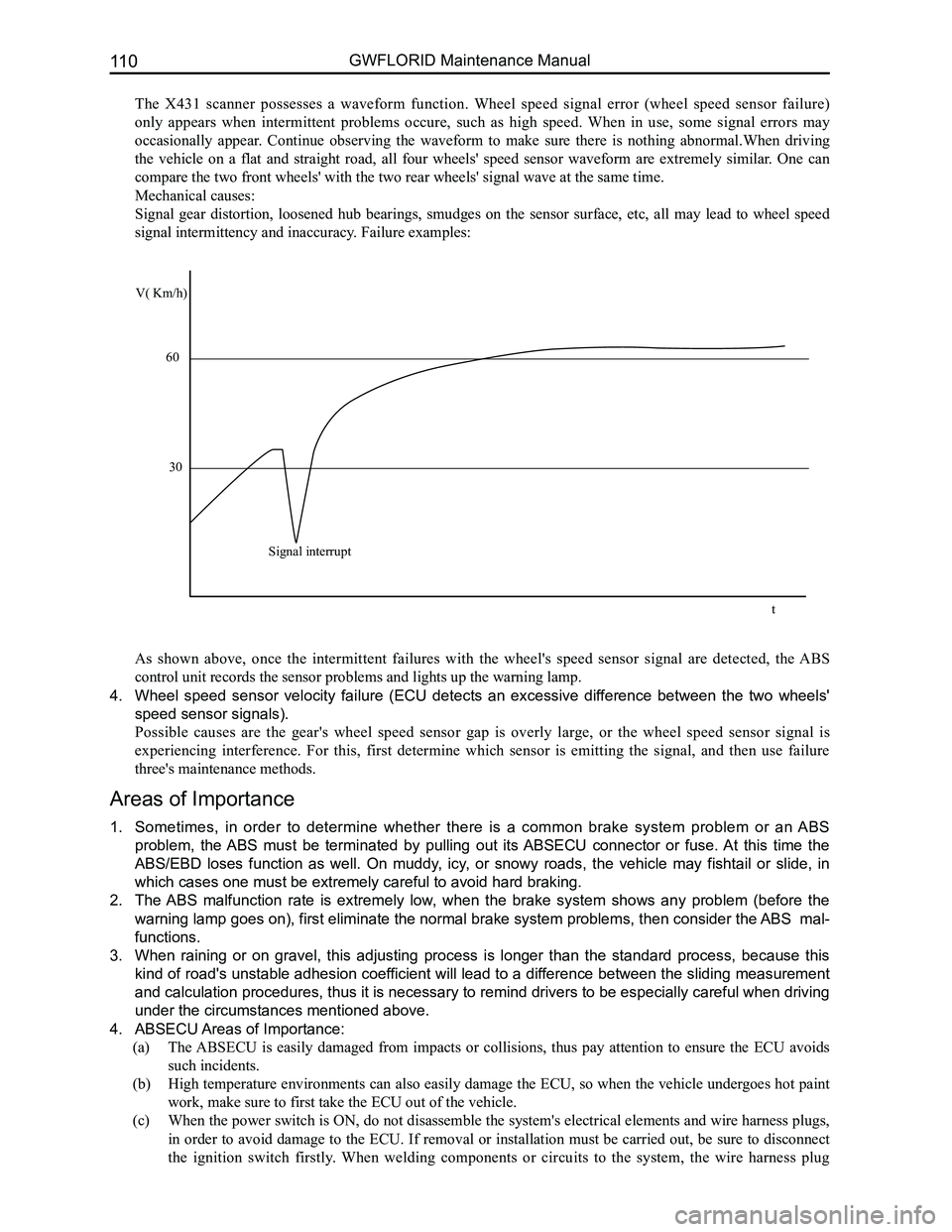
The X431 scanner possesses a waveform function. Wheel speed signal error (wheel speed sensor failure)
only appears when intermittent problems occure, such as high speed. When in use, some signal errors may
occasionally appear. Continue observing the waveform to make sure there is nothing abnormal.When driving
the vehicle on a flat and straight road, all four wheels' speed sensor waveform are extremely similar. One can
compare the two front wheels' with the two rear wheels' signal wave at t\
he same time.
Mechanical causes:
Signal gear distortion, loosened hub bearings, smudges on the sensor surface, etc, all may lead to wheel speed
signal intermittency and inaccuracy. Failure examples:
As shown above, once the intermittent failures with the wheel's speed sensor signal are detected, the ABS
control unit records the sensor problems and lights up the warning lamp.\
4. Wheel speed sensor velocity failure (ECU detects an excessive difference between the two wheels'
speed sensor signals).
Possible causes are the gear's wheel speed sensor gap is overly large, or the wheel speed sensor signal is
experiencing interference. For this, first determine which sensor is emitting the signal, and then use failure
three's maintenance methods.
Areas of Importance
1. Sometimes, in order to determine whether there is a common brake system problem or an ABS
problem, the ABS must be terminated by pulling out its ABSECU connector or fuse. At this time the
ABS/EBD loses function as well. On muddy, icy, or snowy roads, the vehicle may fishtail or slide, in
which cases one must be extremely careful to avoid hard braking.
2. The ABS malfunction rate is extremely low, when the brake system shows any problem (before the
warning lamp goes on), first eliminate the normal brake system problems, then consider the ABS mal-
functions.
3. When raining or on gravel, this adjusting process is longer than the standard process, because this
kind of road's unstable adhesion coefficient will lead to a difference between the sliding measurement
and calculation procedures, thus it is necessary to remind drivers to be especially careful when driving
under the circumstances mentioned above.
4. ABSECU Areas of Importance:
(a) The ABSECU is easily damaged from impacts or collisions, thus pay attention to ensure the ECU avoids
such incidents.
(b) High temperature environments can also easily damage the ECU, so when the vehicle undergoes hot paint
work, make sure to first take the ECU out of the vehicle.
(c) When the power switch is ON, do not disassemble the system's electrical elements and wire harness plugs,
in order to avoid damage to the ECU. If removal or installation must be carried out, be sure to disconnect
the ignition switch firstly. When welding components or circuits to the system, the wire harness plug
V( Km/h)
60
30
Signal interrupt
t