Page 118 of 281

Downloaded from www.Manualslib.com manuals search engine 111Brake System
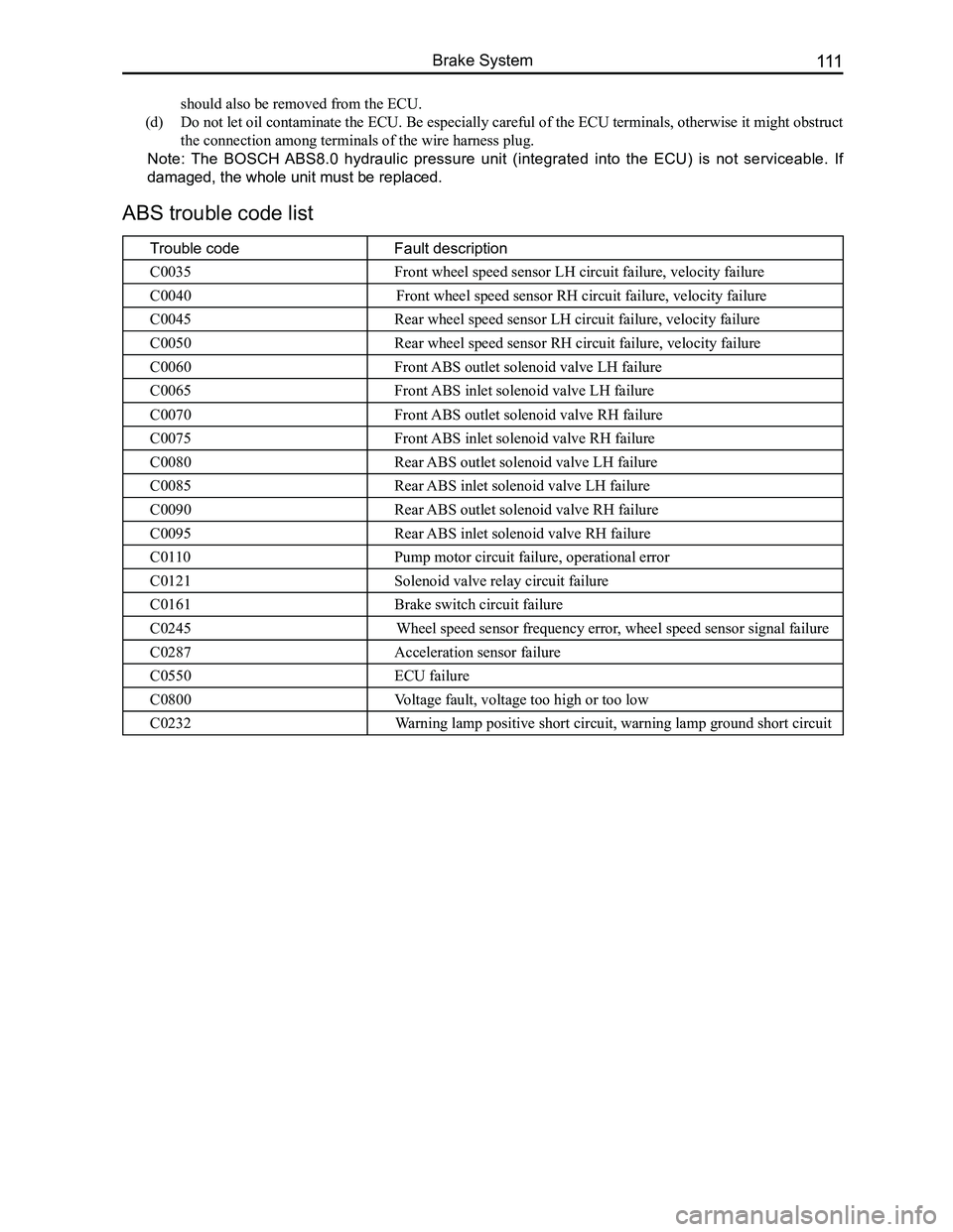
ABS trouble code list
Trouble codeFault description
C0035Front wheel speed sensor LH circuit failure, velocity failure
C0040Front wheel speed sensor RH circuit failure, velocity failure
C0045Rear wheel speed sensor LH circuit failure, velocity failure
C0050Rear wheel speed sensor RH circuit failure, velocity failure
C0060Front ABS outlet solenoid valve LH failure
C0065Front ABS inlet solenoid valve LH failure
C0070Front ABS outlet solenoid valve RH failure
C0075Front ABS inlet solenoid valve RH failure
C0080Rear ABS outlet solenoid valve LH failure
C0085Rear ABS inlet solenoid valve LH failure
C0090Rear ABS outlet solenoid valve RH failure
C0095Rear ABS inlet solenoid valve RH failure
C0110Pump motor circuit failure, operational error
C0121Solenoid valve relay circuit failure
C0161Brake switch circuit failure
C0245Wheel speed sensor frequency error, wheel speed sensor signal failure
C0287Acceleration sensor failure
C0550ECU failure
C0800Voltage fault, voltage too high or too low
C0232Warning lamp positive short circuit, warning lamp ground short circuit
should also be removed from the ECU.
(d) Do not let oil contaminate the ECU. Be especially careful of the ECU terminals, otherwise it might obstruct
the connection among terminals of the wire harness plug.
Note: The BOSCH ABS8.0 hydraulic pressure unit (integrated into the ECU) is not serviceable. If
damaged, the whole unit must be replaced.
Page 119 of 281

Downloaded from www.Manualslib.com manuals search engine GWFLORID Maintenance Manual112
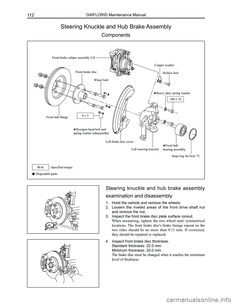
Steering Knuckle and Hub Brake Assembly
Components
Disposable parts
Steering knuckle and hub brake assembly
examination and disassembly
1. Hoist the vehicle and remove the wheels.
2. Loosen the riveted areas of the front drive shaft nut
and remove the nut.
3. Inspect the front brake disc plate surface runout.
When measuring, tighten the two wheel nuts' symmetrical
locations. The front brake disc's brake linings runout on the
two sides should be no more than 0.11 mm. If oversized,
they should be repaired or replaced.
4. Inspect front brake disc thickness.
Standard thickness: 22.0 mm
Minimum thickness: 20.0 mm
The brake disc must be changed when it reaches the minimum
level of thickness.
Front brake caliper assembly LH
Copper washer
Hollow bolt
♦Heavy duty spring washer
Snap ring for hole 72
♦Front hub
bearing assemblyLeft steering knuckle
Left brake disc cover
♦Hexagon head bolt and
spring washer subassembly
Wheel bolt
Front hub flange
Front brake disc
100 ± 10
: Specified torqueN·m
9 ± 2
Page 121 of 281

Downloaded from www.Manualslib.com manuals search engine GWFLORID Maintenance Manual114
(d) Measure the front hub bearing's starting torque.
Put the SST on the wheel bolts which are at the symmetric
locations. Put a dial torque wrench on the SST to slowly
rotate the flange assembly (45°/4s), requiring a starting
torque range of 0.1-0.3 N·m.
If the bearing rotation is not flexible, the front hub flange
plate surface movement inaccurate, or front hub bearing
starting torque is too much. The assembly must be replaced.
Steering knuckle's front hub bearing and
front hub flange assembly
1. Removal and inspection of front hub flange assembly.
(a) Use SST like a hand held travel hammer to repeatedly
hammer off the front hub flange assembly from the
steering knuckle and front hub bearing. Remove the
front hub with bearing's inner ring.
(b) Remove the bearing's inner ring on the front hub.
Use SST to remove the bearing's inner ring.
SST
SST
Bearing inner ring
SST
(c) Use dye penetrant to inspect the front hub flange for
cracks, which should be replaced if found.
(d) If one would like to continue using the front hub flange
assembly, first inspect the dimensions for the mounting
area of the bearing for inaccurate dimensions. If
oversized, replace.
Measurement range: Φ38+0.025 +0.009 mm
2. Remove the steering knuckle's front hub bearing.
3. Remove the snap ring for hole 72.
Use a bent nose retaining ring caliper for holes to remove the
snap ring for hole 72.
Page 123 of 281

Downloaded from www.Manualslib.com manuals search engine GWFLORID Maintenance Manual116
3. Examine the front hub flange plate surface runout.
Examining methods are the same as the methods used
during disassembly. Plate surface runout should not exceed
0.03 mm.
4. Examine the front hub bearing assembly's starting
torque.
Examining methods are the same as the methods used during
disassembly. Put the SST on the wheel bolts which are at the
symmetrical locations. Put a dial torque wrench on the SST to
slowly rotate the flange's flange assembly (45°/4s), which re-
quires a starting torque range of 0.1-0.3 N·m
5. Install the snap ring for hole 72.
Use a bent nose retaining ring caliper for holes to install the
snap ring for hole 72 at the steering knuckle's retaining ring
mounting position.
6. Install the steering knuckle's front hub bearing and
front hub flange assembly.
7. Install the front brake disc cover.
Install the front brake disc cover on the steering knuckle, and
tighten the bolt to the set torque.
Tightening torque: 9±2 N·m
SST
8. Install the front brake disc.
Page 124 of 281
Downloaded from www.Manualslib.com manuals search engine 117Brake System
9. Examine the front brake disc plate surface runout.
When measuring, tighten the two wheel nut's symmetrical
locations. The front brake disc's brake linings runout on the
two sides should be less than 0.11 mm.
10. Install the brake caliper assembly.
Install the brake caliper on the steering knuckle, and tighten
the bolt according to the set torque.
Tightening torque: 100±10 N·m
Page 125 of 281

Downloaded from www.Manualslib.com manuals search engine GWFLORID Maintenance Manual118
Front Brake Caliper
Components
Disposable parts
Inner and outer brake pad assembly re-
placement
Remark: When applying the brake while driving, if the front
tires makes a continuous screeching sound, inspect the inner
and outer brake pad and friction limit alarm plate. If there
are traces of rubbing from the brake disc on the alarm plate,
the inner and outer brake pad assembly should be replaced.
1. Remove the front wheel.
2. Inspect the inner and outer brake pad's friction material
thickness.
By looking through the caliper's observation ports, inspect
the inner and outer brake pad friction material thickness. If it
is no longer within the specified range, it should be replaced.
Minimum thickness: 2.0 mm
Bleed screw cap
Air bleed screw
Caliper
Rectangular sealing ring
Piston
P iston dust cover
Inner muffler plate subassembly
Alarm plate
Inner brake pad assembly
Outer brake pad assembly
Outer muffler plate subassembly
Guide pin
Guide pin dust cover
Caliper frame
Brake block yoke spring plate
Brake block yoke spring plate
30 ± 5
: Specified torqueN·m
10 ± 2
Q1840820
Rubber grease
Page 127 of 281

Downloaded from www.Manualslib.com manuals search engine GWFLORID Maintenance Manual120
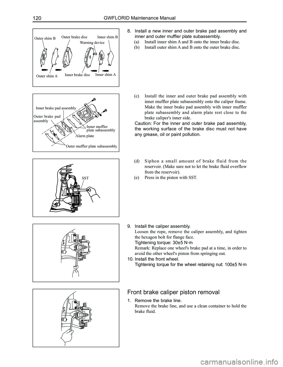
8. Install a new inner and outer brake pad assembly and
inner and outer muffler plate subassembly.
(a) Install inner shim A and B onto the inner brake disc.
(b) Install outer shim A and B onto the outer brake disc.
(c) Install the inner and outer brake pad assembly with
inner muffler plate subassembly onto the caliper frame.
Make the inner brake pad assembly with inner muffler
plate subassembly and alarm plate rest close to the
brake caliper's inner side.
Caution: For the inner and outer brake pad assembly,
the working surface of the brake disc must not have
any grease, oil or paint pollution.
(d) S i p h o n a s m a l l a m o u n t o f b r a k e f l u i d f r o m t h e
reservoir. (Make sure not to let the brake fluid overflow
from the reservoir).
(e) Press in the piston with SST.
9. Install the caliper assembly.
Loosen the rope, remove the caliper assembly, and tighten
the hexagon bolt for flange face.
Tightening torque: 30±5 N·m
Remark: Replace one wheel's brake pad at a time, in order to
avoid the other wheel's piston from springing out.
10. Install the front wheel.
Tightening torque for the wheel retaining nut: 100±5 N·m
Front brake caliper piston removal
1. Remove the brake line.
Remove the brake line, and use a clean container to hold the
brake fluid.
SST
Outer shim B
Outer shim AInner brake disc
Warning device
Inner shim B
Inner shim A
Outer brake disc
Inner muffler plate subassembly
Alarm plate
Inner brake pad assembly
Outer brake pad assembly
Outer muffler plate subassembly
Page 131 of 281

Downloaded from www.Manualslib.com manuals search engine GWFLORID Maintenance Manual124
Rear Brake
Components
4. Remove the rear brake drum.
Remark: If it is difficult to remove the rear brake drum,
follow the steps below:
Method one:
(a) Remove the rubber plug of the adjuster's observation
port, and insert a slotted screwdriver into the brake's
back plate assembly hole, and pry off the adjusting
paddle from the adjusting clearance wheel.
(b) Use another slotted screwdriver to toggle the adjusting
clearance wheel and loosen the brake's leading and
trailing shoe assembly's tension on the rear brake drum.
Disposable parts
Dust cover
Brake leading shoe assembly
Pressure spring
Pressure spring cap
Brake shoe tension spring
Rear brake drum
Lever rotating shaft
Retainer spring
Locking cap
Split ring
Brake lever
Brake trailing shoe assembly
Brake back plate assembly
Pressure spring bar
Rubber plug of the adjuster's observation port
Rubber plug of the observation port gap
Washer
Bleed screw cap
Bleed screwPiston
Ring cup
Piston spring
Wheel cylinder
Adjusting clearance shaft head
Adjusting clearance wheel
Adjusting clearance screw rod
Return springAdjusting paddle
Pin
Side spring
Dust cover
Piston
Ring cup
Rubber grease
: Specified torqueN·m
7.8-11.8
High temperature resistant grease
Rear brake removal
1. Inspecting the brake's friction plate thickness.
Remove the rubber plug of the observation port gap and
examine the friction plate thickness via the observation port.
If it's smaller than the minimum value, the brake's leading
and trailing shoe assemblies should be replaced.
Minimum thickness: 1.0 mm
2. Remove the rear wheel.
3. Release the brake fluid.
Caution: Be sure not to spill the brake fluid onto the
paint's surface. Otherwise it must be immediately
cleaned.