2008 GREAT WALL FLORID warning
[x] Cancel search: warningPage 104 of 281

Downloaded from www.Manualslib.com manuals search engine 97Brake System
(e) Make sure not to let the system valves block the air bleeding.
(f) When the brake fluid that flows out of the hose or connector has no bubbles, it means that the air
in the system has been exhausted. There is still air inside the system if the hose inserted into the
brake fluid is still bubbling when pressing down the pedal.
(g) Keep the free end of the hose immerged in the brake fluid to avoid air from flowing into the
system while opening the screw.
(h) While air bleeding, hammer the casting part of the vibrating brake device with a rubber hammer.
This is helpful for removing bubbles deep in the brake fluid.
(i) If air in the master cylinder is suspected, then perform air bleeding on the master cylinder first,
then the wheel cylinder or brake caliper.
(j) When releasing air from the tires, generally make sure to release air out of all the tires.
(k) To avoid the possibility of air reversely entering into the system, a bleeder hose that has a check
valve could be used.
(2) Pressure blow-off
Under the proper conditions, a pressure blow-off device can be used to release the air inside the brake system.
3. Air releasing sequence
(1) Master cylinder air bleeding
If the master cylinder does not have air bleed screws, perform the follo\
wing steps:
(a) Check the brake fluid level inside the master cylinder’s reservoir and add to it if necessary.
(b) Slowly take off the front brake pipe connector until the brake fluid flows out from the end.
(c) Reconnect the brake pipe, but do not tighten it.
(d) Slowly step down and press on the brake pedal, check if the brake fluid flowing out of the connector
contains bubbles.
(e) Tighten the pipe fitting.
(f) Have the assistant loosen the pedal, wait for 15 s.
(g) Repeat the above steps until all the air is released.
(h) Take off the rear brake pipe connector, repeat the above steps.
(2) Wheel brake air releasing
(a) Check the brake fluid level inside the master cylinder’s reservoir and add to it if necessary. During the
entire air releasing period, check repeatedly and add promptly.
(b) Connect one end of the bleeder hose with the bleed screw and the other end immerged in the brake fluid.
(c) Have the assistant step on the pedal several times, raise the pedal gradually until it cannot be stepped on
any more, then forcibly press on the pedal once more.
(d) Loosen the bleed screw, check if there are any bubbles in the brake fluid flowing out. Meanwhile, slowly
lower the pedal.
(e) When the brake pedal is close to the stroke end or the out flowing brake fluid does not have any bubbles,
tighten the bleed screw.
(f) Have the assistant release the pedal and wait for 15 s.
(g) Repeat the above steps until there are no bubbles in the flowing brake fluid when the screw is loosened.
(h) Release the air for all the wheels in turn using the same method.
(i) After releasing the air from the entire system, switch the ignition to the on position.
(j) Inspect the stroke of the brake pedal and its reaction.
(k) Inspect the lighting condition of the brake warning lamp, and repeatedly perform maintenance or air
bleeding if necessary.
( l ) Add brake fluid to the reservoir until the specified fluid level, air bleeding is complete.
Page 117 of 281
Downloaded from www.Manualslib.com manuals search engine GWFLORID Maintenance Manual110
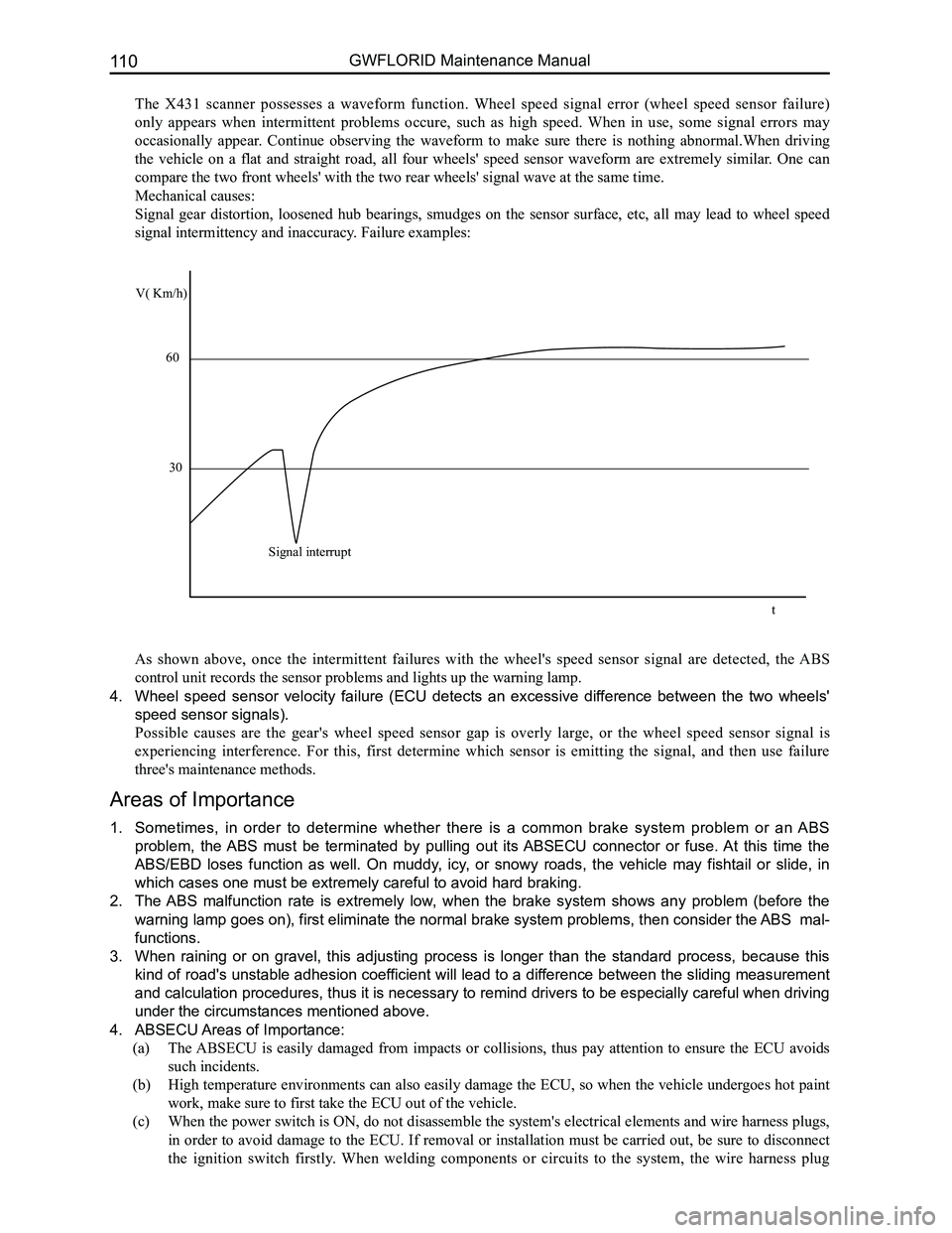
The X431 scanner possesses a waveform function. Wheel speed signal error (wheel speed sensor failure)
only appears when intermittent problems occure, such as high speed. When in use, some signal errors may
occasionally appear. Continue observing the waveform to make sure there is nothing abnormal.When driving
the vehicle on a flat and straight road, all four wheels' speed sensor waveform are extremely similar. One can
compare the two front wheels' with the two rear wheels' signal wave at t\
he same time.
Mechanical causes:
Signal gear distortion, loosened hub bearings, smudges on the sensor surface, etc, all may lead to wheel speed
signal intermittency and inaccuracy. Failure examples:
As shown above, once the intermittent failures with the wheel's speed sensor signal are detected, the ABS
control unit records the sensor problems and lights up the warning lamp.\
4. Wheel speed sensor velocity failure (ECU detects an excessive difference between the two wheels'
speed sensor signals).
Possible causes are the gear's wheel speed sensor gap is overly large, or the wheel speed sensor signal is
experiencing interference. For this, first determine which sensor is emitting the signal, and then use failure
three's maintenance methods.
Areas of Importance
1. Sometimes, in order to determine whether there is a common brake system problem or an ABS
problem, the ABS must be terminated by pulling out its ABSECU connector or fuse. At this time the
ABS/EBD loses function as well. On muddy, icy, or snowy roads, the vehicle may fishtail or slide, in
which cases one must be extremely careful to avoid hard braking.
2. The ABS malfunction rate is extremely low, when the brake system shows any problem (before the
warning lamp goes on), first eliminate the normal brake system problems, then consider the ABS mal-
functions.
3. When raining or on gravel, this adjusting process is longer than the standard process, because this
kind of road's unstable adhesion coefficient will lead to a difference between the sliding measurement
and calculation procedures, thus it is necessary to remind drivers to be especially careful when driving
under the circumstances mentioned above.
4. ABSECU Areas of Importance:
(a) The ABSECU is easily damaged from impacts or collisions, thus pay attention to ensure the ECU avoids
such incidents.
(b) High temperature environments can also easily damage the ECU, so when the vehicle undergoes hot paint
work, make sure to first take the ECU out of the vehicle.
(c) When the power switch is ON, do not disassemble the system's electrical elements and wire harness plugs,
in order to avoid damage to the ECU. If removal or installation must be carried out, be sure to disconnect
the ignition switch firstly. When welding components or circuits to the system, the wire harness plug
V( Km/h)
60
30
Signal interrupt
t
Page 118 of 281
Downloaded from www.Manualslib.com manuals search engine 111Brake System
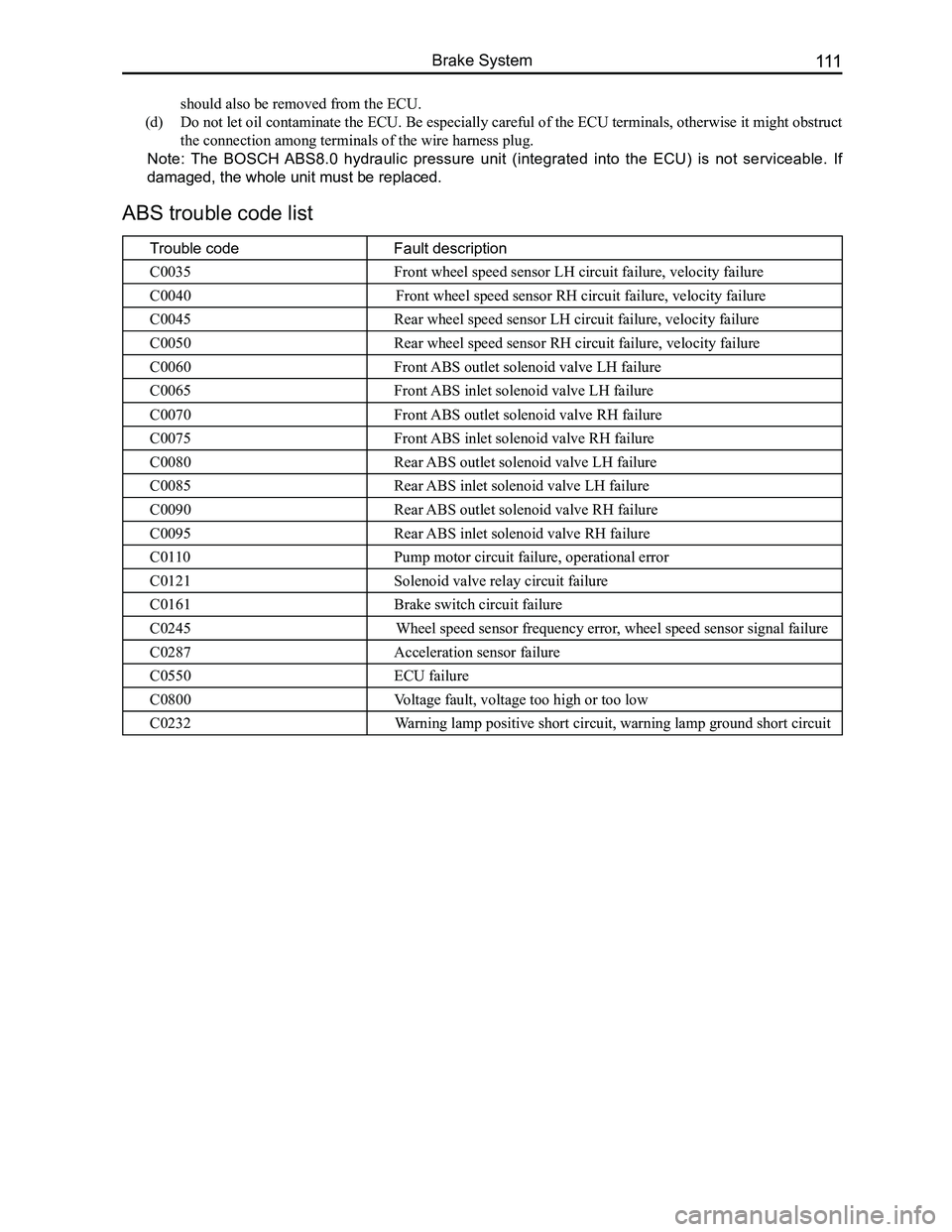
ABS trouble code list
Trouble codeFault description
C0035Front wheel speed sensor LH circuit failure, velocity failure
C0040Front wheel speed sensor RH circuit failure, velocity failure
C0045Rear wheel speed sensor LH circuit failure, velocity failure
C0050Rear wheel speed sensor RH circuit failure, velocity failure
C0060Front ABS outlet solenoid valve LH failure
C0065Front ABS inlet solenoid valve LH failure
C0070Front ABS outlet solenoid valve RH failure
C0075Front ABS inlet solenoid valve RH failure
C0080Rear ABS outlet solenoid valve LH failure
C0085Rear ABS inlet solenoid valve LH failure
C0090Rear ABS outlet solenoid valve RH failure
C0095Rear ABS inlet solenoid valve RH failure
C0110Pump motor circuit failure, operational error
C0121Solenoid valve relay circuit failure
C0161Brake switch circuit failure
C0245Wheel speed sensor frequency error, wheel speed sensor signal failure
C0287Acceleration sensor failure
C0550ECU failure
C0800Voltage fault, voltage too high or too low
C0232Warning lamp positive short circuit, warning lamp ground short circuit
should also be removed from the ECU.
(d) Do not let oil contaminate the ECU. Be especially careful of the ECU terminals, otherwise it might obstruct
the connection among terminals of the wire harness plug.
Note: The BOSCH ABS8.0 hydraulic pressure unit (integrated into the ECU) is not serviceable. If
damaged, the whole unit must be replaced.
Page 126 of 281

Downloaded from www.Manualslib.com manuals search engine 119Brake System
3. Remove the caliper assembly.
(a) Remove the hexagon bolt for flange face connecting
the caliper and caliper frame's lower end.
(b) Lift the caliper assembly and use a rope to hang it up to
protect the brake pipeline.
Remark: Do not unscrew the brake pipeline and bleed screw.
4. Remove the following parts.
(a) The group of inner and outer shims B.
(b) The group of inner and outer shims A.
(c) The group of inner and outer brake discs.
(d) One pair of yoke springs.
5. Measure the brake disc thickness.
(See steering knuckle and hub brake assembly examination and
disassembly step 4).
6. Measure the brake disc radial runout.
(See steering knuckle and hub brake assembly examination and
disassembly step 3).
7. Install the yoke spring.
Install the brake block yoke spring plate to the caliper frame.
Outer shim B
Outer shim AInner brake disc
Warning device
Inner shim B
Inner shim A
Outer brake disc
Yoke spring
Page 127 of 281
Downloaded from www.Manualslib.com manuals search engine GWFLORID Maintenance Manual120
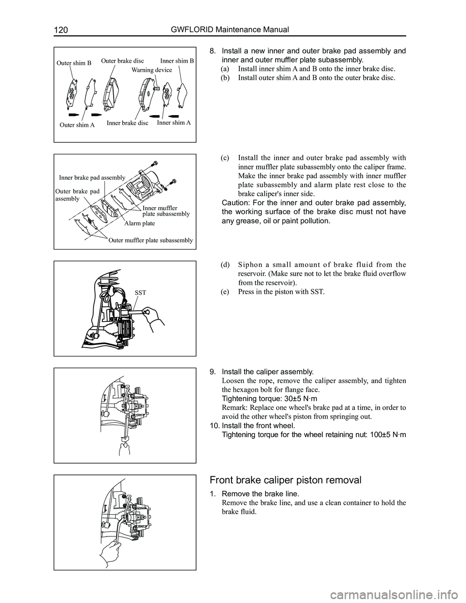
8. Install a new inner and outer brake pad assembly and
inner and outer muffler plate subassembly.
(a) Install inner shim A and B onto the inner brake disc.
(b) Install outer shim A and B onto the outer brake disc.
(c) Install the inner and outer brake pad assembly with
inner muffler plate subassembly onto the caliper frame.
Make the inner brake pad assembly with inner muffler
plate subassembly and alarm plate rest close to the
brake caliper's inner side.
Caution: For the inner and outer brake pad assembly,
the working surface of the brake disc must not have
any grease, oil or paint pollution.
(d) S i p h o n a s m a l l a m o u n t o f b r a k e f l u i d f r o m t h e
reservoir. (Make sure not to let the brake fluid overflow
from the reservoir).
(e) Press in the piston with SST.
9. Install the caliper assembly.
Loosen the rope, remove the caliper assembly, and tighten
the hexagon bolt for flange face.
Tightening torque: 30±5 N·m
Remark: Replace one wheel's brake pad at a time, in order to
avoid the other wheel's piston from springing out.
10. Install the front wheel.
Tightening torque for the wheel retaining nut: 100±5 N·m
Front brake caliper piston removal
1. Remove the brake line.
Remove the brake line, and use a clean container to hold the
brake fluid.
SST
Outer shim B
Outer shim AInner brake disc
Warning device
Inner shim B
Inner shim A
Outer brake disc
Inner muffler plate subassembly
Alarm plate
Inner brake pad assembly
Outer brake pad assembly
Outer muffler plate subassembly
Page 128 of 281

Downloaded from www.Manualslib.com manuals search engine 121Brake System
2. Remove the caliper assembly.
(a) Remove the two hexagon bolts for flange face connecting
the caliper and caliper frame.
(b) Remove the caliper assembly from the caliper frame.
3. Remove the following parts.
(a) The group of inner and outer shims B.
(b) The group of inner and outer shims A.
(c) The group of inner and outer brake discs.
(d) One pair of yoke springs.
4. Remove the piston and piston dust cover from the
caliper.
(a) Place a block in the middle of the caliper.
(b) Use an airgun or air pipe to align the brake pipeline
holes. Remove the piston from the caliper, and at the
same time remove the piston dust cover.
(c) Use a clean rag or other soft cloth to extract the piston.
Warning: When using compressed air, be sure not to
place fingers in front of the piston.
5. Remove the rectangular sealing ring from the caliper.
Use a paperclip to remove the rectangular sealing ring from
the caliper.
Caution: The tools being used should not be sharp, in
order to avoid tearing the rectangular sealing ring.
Inner and outer brake pad assembly exami-
nation
Measure the inner and outer brake pad assembly's thickness.
Standard thickness: 8.5 mm
Minimum thickness: 2.0 mm
If it is smaller than the minimum level of thickness or there
are traces of uneven wear and tear, the brake pad should be
replaced.
Page 151 of 281
Downloaded from www.Manualslib.com manuals search engine GWFLORID Maintenance Manual144
Double-colored wire: Primary color is Red, secondary color is Blue, mark\
ed as RBl.
0.5BrGr means Brown wire with a Gray fine wire, and sectional area is 0.\
5 mm2.
Areas of importance in circuit maintenance
1. Before operating any electronic devices, and when tools or maintenance devices may easily make
contact with an uncovered electronic terminal, please make sure to turn the ignition switch to the LOCK
position, and then disconnect the battery's negative cable to avoid injury or vehicle damage. When the
ignition switch is on the ON position, please do not disconnect the battery's connecting wire or take out
the power's fuse, regardless if the engine is running or not.Otherwise it would seriously damage the
ECU and related microelectronic devices such as sensors.
2. When changing the fuse, please make sure that the new fuse possesses the proper current rating,
and is not above or below this rating.
3. When repairing the wire harnesses of the airbag and pretensioner, only specified contact points,
plugs, and wires are allowed to be used.
4. Before repairing the wire harness, make sure to eliminate any factor that might cause damage,
for example, the edge of a vehicle body part is too sharp, or the used electronics are damaged or
corroded.
5. Shielded wire should not be repaired, it must be replaced entirely once it is damaged.
6. Unless it is specified during the test, please do not use an analog multimeter to test the ECU and
sensor, instead use a high-impedance digital multimeter (internal resistance should be ≥10 kΩ) or a
vehicle multimeter for inspection.
7. When inspecting the connector with a digital multimeter, take the waterproof rubber cover off the
connector, and tightly insert the test pen along the connecting terminal. Don't use too much force, as
to avoid cracking the connector.
Circuit inspection steps
The principle of troubleshooting is to confirm the "possible cause". Once the possible cause is confirmed, the
components that need to be inspected are limited to the components that are related to the possible cause. The
confirmed possible cause should be based on theory and be supported by facts, but not just by intuition. If
one tries to solve the problem but does not adopt the proper troubleshooting steps, it may make the problem
worse. Then the possible cause not only can't be confirmed, but also maintenance can't be performed properly.
Troubleshooting should adhere to the four steps below:
1. Observe the symptoms carefully, inspect if there is anything else abnormal, and record it.
2. While confirming the possible causes, study the circuit diagram carefully, and regard it as a whole
system in order to understand the circuit. Thorough knowledge of switches, relays, and other
electronic components is obligatory for proper analysis.
3. Inspect and eliminate the problems one by one until the cause is found.
4. After the malfunction is fixed, make sure to check if the inspected system is working properly, and also
check if the maintenance may have caused any new problems.
Compres-
sor relay
Reserve
Sunroof (Elite) Lamplet
Reserve
Reserve
Reserve
Reserve Door and window Reserve Blower
Lamplet
relay Flasher relay Blower high
speed relay (Elite) Door and
window relay (Comfort, Luxury) Blower relay
Reserve
Front fog lamp
Combination
meter
Interior
lighting
central
door lock
brake lamp
CD player
Reserve
Reserve
Reserve
Cigarette
lighter
Rearview
mirror
Front wiper
Charge
Airbag
Reserve
Reverse lamp Rear fog lamp
Rear wiper
Defroster Compressor
ACC relay
IG relayRear wiper
relay Defroster
relay
Front fog
lamp relay Rear fog
lamp relay
Warning lamp
Turn signal lamp
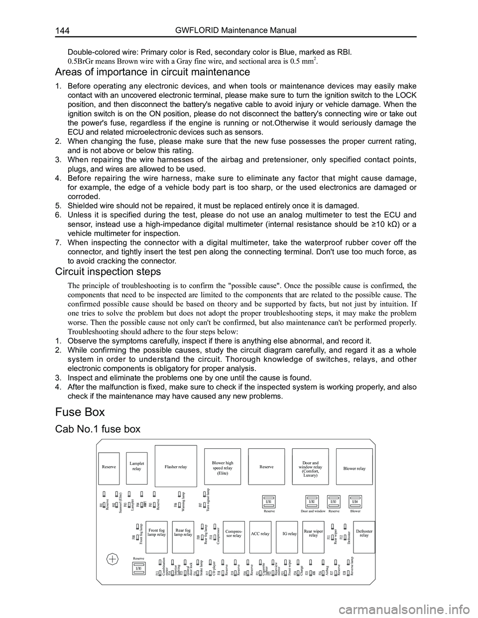
Cab No.1 fuse box
Fuse Box
Page 152 of 281
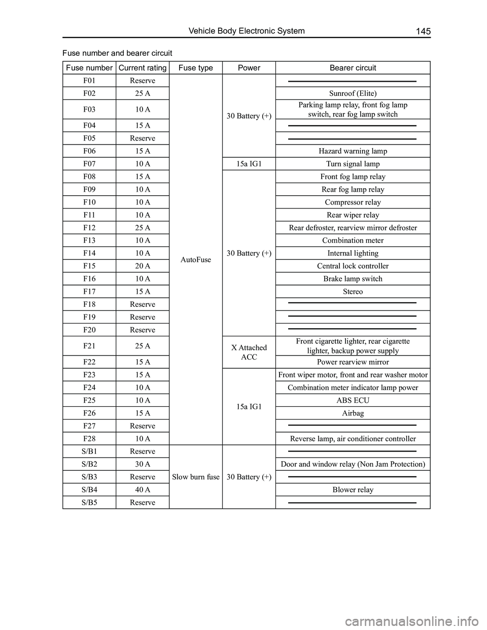
Downloaded from www.Manualslib.com manuals search engine 145Vehicle Body Electronic System
Fuse numberCurrent ratingFuse typePowerBearer circuit
F01Reserve
AutoFuse
30 Battery (+)
F0225 ASunroof (Elite)
F0310 AParking lamp relay, front fog lamp
switch, rear fog lamp switch
F0415 A
F05Reserve
F0615 AHazard warning lamp
F0710 A15a IG1 Turn signal lamp
F0815 A
30 Battery (+)
Front fog lamp relay
F0910 ARear fog lamp relay
F1010 ACompressor relay
F1110 ARear wiper relay
F1225 ARear defroster, rearview mirror defroster
F1310 ACombination meter
F1410 AInternal lighting
F1520 ACentral lock controller
F1610 ABrake lamp switch
F1715 AStereo
F18Reserve
F19Reserve
F20Reserve
F2125 AX Attached
ACC
Front cigarette lighter, rear cigarette
lighter, backup power supply
F2215 APower rearview mirror
F2315 A
15a IG1
Front wiper motor, front and rear washer motor
F2410 ACombination meter indicator lamp power
F2510 AABS ECU
F2615 AAirbag
F27Reserve
F2810 AReverse lamp, air conditioner controller
S/B1Reserve
Slow burn fuse 30 Battery (+)
S/B230 ADoor and window relay (Non Jam Protection)
S/B3Reserve
S/B440 ABlower relay
S/B5Reserve
Fuse number and bearer circuit