2008 GREAT WALL FLORID light
[x] Cancel search: lightPage 85 of 281

Downloaded from www.Manualslib.com manuals search engine GWFLORID Maintenance Manual78
Remark: When removing the subframe's front mounting bolt,
an extension bar should be inserted through the lower swing
arm's hole. Positions shown on the left.
5. Subframe installation.
Installation follows the reverse removal steps.
Caution: Fix the position of the subframe with the
position pin, to avoid influencing the four wheels'
positioning. Location hole is shown on the left: a total
of two, one on the left and one on the right.
Stabilizer bar removal and installation
1. Remove the hanger rod.
Use a M10 open-end wrench to lock the sliding side of the
hanger rod (slightly higher than center position), screw off
the hanger rod lock nuts, and remove the hanger rod.
Caution: These are non-metal insert lock nuts, and
cannot be reused. So please replace them with new
ones after removal.
2. Remove the stabilizer bar arm.
Remove the stabilizer bar bracket mounting bolts Q1400830
(d2=13.5), and take down the bracket and bushing. As shown
on the left: There are four bolts, two on the left and two on
the right.
Tightening torque: 23±3 N·m
3. Stabilizer bar installation.
Install it by reversing the removal steps, but please pay
attention to the areas of importance below:
(a) During removal, please remember the installation order
of each of the hanger rod's components, so as to avoid
improper installation.
Insert extension bar through this hole
This is the subframe location hole
Q1400830
WasherBushingHanger rod
Shaft sleeve
BushingWasher
Page 99 of 281

Downloaded from www.Manualslib.com manuals search engine GWFLORID Maintenance Manual92
Wheel
General tire balancing procedures
Clean out the accumulated dirt and debris from the inside of the rim.
Warning:
The gravel on the tread must be eliminated to avoid flying out and injuring the operator when
undergoing rotational balancing. This is also a good way to acquire better balance. First thoroughly
inspect the tire's damaged condition, then according to the balancing device manufacture's
recommendations, carry out the balancing operation.
Off-vehicle balancing
Most off-vehicle balancers are more accurate and convenient than on-vehicle rotational balancers. They are
also able to perform dynamic (two sided) balancing. Although it does not correct drum brake and brake disc
imbalance like on-vehicle balancing, it achieves the same effect based on its accuracy.
On-vehicle balancing
On-vehicle balancing is different based on equipment and tool manufacturer. Therefore, when performing
balancing operations, be sure to comply to each manufacturer's operating\
instructions.
Warning: Control the wheel rotation speed to make sure the speedometer stays within 55 km/h.
This restriction is necessary because when a driven wheel slides while the other one stays still, the
speedometer will display only half of the actual wheel speed. When a wheel is sliding, be extremely
careful, because sliding wheels can reach very high speeds. This may lead to the tire rubber peeling
or differential damage, which may cause serious personal injury, or damage to the vehicle.
Tire installation and removal
• Install or remove tires with a tire changer. When operating machinery, make sure to comply to the machine
manufacturers operation manual. Please do not change tires merely with manual hand tools or tire installation
crowbars. This will damage the tire chafer or the vehicle wheel's rim.
• Use a wire brush or coarse steel wool to clean off grease and old rubber, as well as light rust or corrosion from
the rim tire bead's tire chafer seat. Before tire installation or removal, first use the indicated tire lubricant to
thoroughly lube the tire chafer portions one time.
• After installing the tire, inflate it to the specified pressure and make\
sure the tire bead is properly seated.
Warning: Do not over-inflate the tire. If the tire bead severally expands and exceeds the safety limit,
it may burst and cause serious personal injury. While inflating, do not exceed the specified pressure.
If the specified pressure does not allow the tire bead to sit properly, deflate the tire, re-lubricate, and
then re-inflate.
Spare tire usage
• Spare tire standard inflation pressure: 420 kPa.
• Spare tire pressure measurements should be taken under normal temperatur\
e conditions.
• After inflating the spare tire, soapy water should be used to check if the air nozzles core is leaking air, then
lock on the air nozzle cap.
• The spare tire should always be kept in a useable state. Check the air p\
ressure at least once a month.
• When the spare tire's working limit, indicated by the remaining pattern's depth, reaches 1.6 mm (and its pat-
tern groove bottom protrudes to the same level), for your safety, please stop using the spare tire.
Caution:
• The "" symbol on the tire bead of the spare tire in-
dicates the set position of the wear index (shown on
the left).
• The spare tire's maximum driven speed is 80 km/h,
and maximum distance 200 km per trip.
• Each vehicle is allowed to use only one spare tire.
• The spare tire is only used as a temporary backup.
Please go to a professional service station immediately
to get the initial tire repaired or replaced.
Page 104 of 281

Downloaded from www.Manualslib.com manuals search engine 97Brake System
(e) Make sure not to let the system valves block the air bleeding.
(f) When the brake fluid that flows out of the hose or connector has no bubbles, it means that the air
in the system has been exhausted. There is still air inside the system if the hose inserted into the
brake fluid is still bubbling when pressing down the pedal.
(g) Keep the free end of the hose immerged in the brake fluid to avoid air from flowing into the
system while opening the screw.
(h) While air bleeding, hammer the casting part of the vibrating brake device with a rubber hammer.
This is helpful for removing bubbles deep in the brake fluid.
(i) If air in the master cylinder is suspected, then perform air bleeding on the master cylinder first,
then the wheel cylinder or brake caliper.
(j) When releasing air from the tires, generally make sure to release air out of all the tires.
(k) To avoid the possibility of air reversely entering into the system, a bleeder hose that has a check
valve could be used.
(2) Pressure blow-off
Under the proper conditions, a pressure blow-off device can be used to release the air inside the brake system.
3. Air releasing sequence
(1) Master cylinder air bleeding
If the master cylinder does not have air bleed screws, perform the follo\
wing steps:
(a) Check the brake fluid level inside the master cylinder’s reservoir and add to it if necessary.
(b) Slowly take off the front brake pipe connector until the brake fluid flows out from the end.
(c) Reconnect the brake pipe, but do not tighten it.
(d) Slowly step down and press on the brake pedal, check if the brake fluid flowing out of the connector
contains bubbles.
(e) Tighten the pipe fitting.
(f) Have the assistant loosen the pedal, wait for 15 s.
(g) Repeat the above steps until all the air is released.
(h) Take off the rear brake pipe connector, repeat the above steps.
(2) Wheel brake air releasing
(a) Check the brake fluid level inside the master cylinder’s reservoir and add to it if necessary. During the
entire air releasing period, check repeatedly and add promptly.
(b) Connect one end of the bleeder hose with the bleed screw and the other end immerged in the brake fluid.
(c) Have the assistant step on the pedal several times, raise the pedal gradually until it cannot be stepped on
any more, then forcibly press on the pedal once more.
(d) Loosen the bleed screw, check if there are any bubbles in the brake fluid flowing out. Meanwhile, slowly
lower the pedal.
(e) When the brake pedal is close to the stroke end or the out flowing brake fluid does not have any bubbles,
tighten the bleed screw.
(f) Have the assistant release the pedal and wait for 15 s.
(g) Repeat the above steps until there are no bubbles in the flowing brake fluid when the screw is loosened.
(h) Release the air for all the wheels in turn using the same method.
(i) After releasing the air from the entire system, switch the ignition to the on position.
(j) Inspect the stroke of the brake pedal and its reaction.
(k) Inspect the lighting condition of the brake warning lamp, and repeatedly perform maintenance or air
bleeding if necessary.
( l ) Add brake fluid to the reservoir until the specified fluid level, air bleeding is complete.
Page 115 of 281
Downloaded from www.Manualslib.com manuals search engine GWFLORID Maintenance Manual108
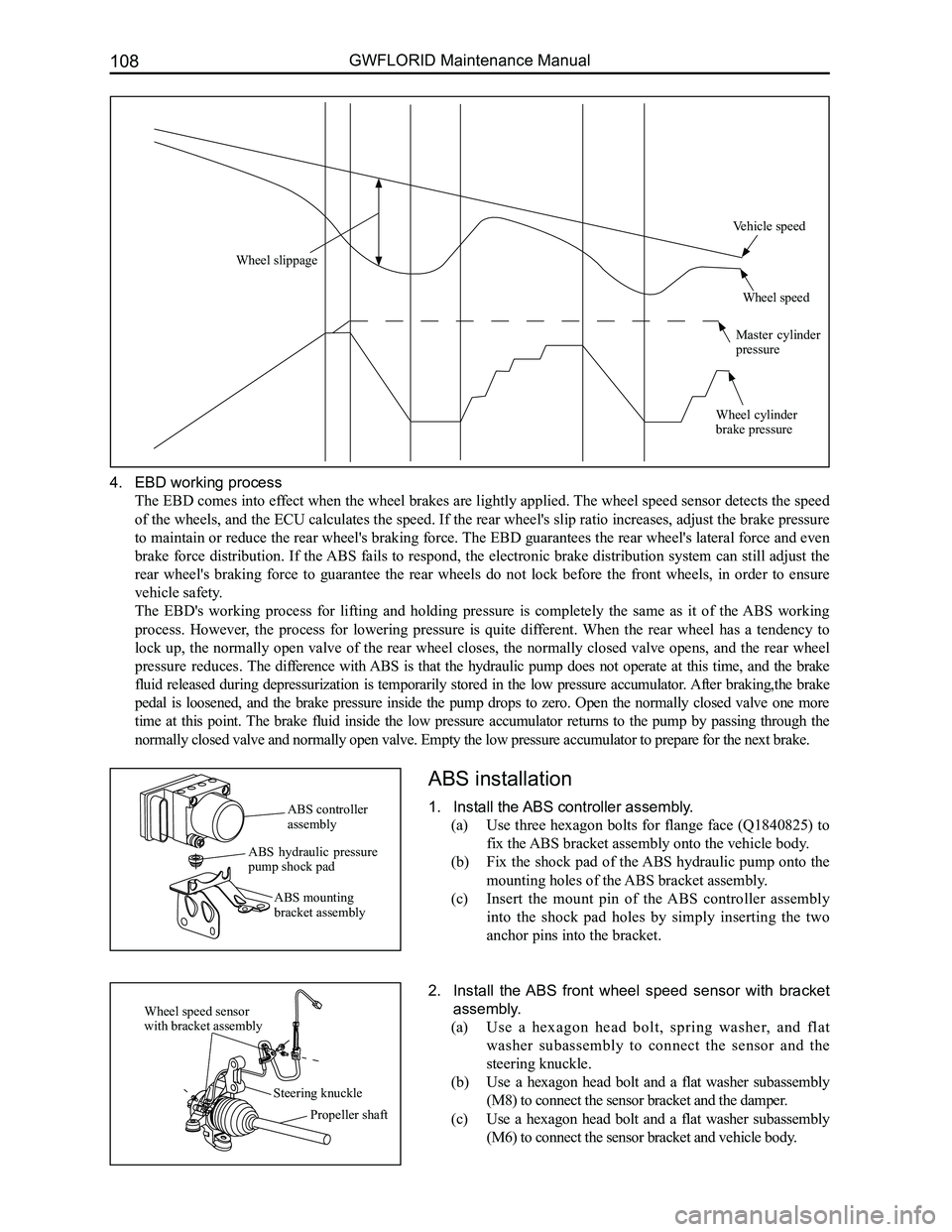
4. EBD working process
The EBD comes into effect when the wheel brakes are lightly applied. The wheel speed sensor detects the speed
of the wheels, and the ECU calculates the speed. If the rear wheel's slip ratio increases, adjust the brake pressure
to maintain or reduce the rear wheel's braking force. The EBD guarantees the rear wheel's lateral force and even
brake force distribution. If the ABS fails to respond, the electronic brake distribution system can still adjust the
rear wheel's braking force to guarantee the rear wheels do not lock before the front wheels, in order to ensure
vehicle safety.
The EBD's working process for lifting and holding pressure is completely the same as it of the ABS working
process. However, the process for lowering pressure is quite different. When the rear wheel has a tendency to
lock up, the normally open valve of the rear wheel closes, the normally closed valve opens, and the rear wheel
pressure reduces. The difference with ABS is that the hydraulic pump does not operate at this time, and the brake
fluid released during depressurization is temporarily stored in the low pressure accumulator. After braking,the brake
pedal is loosened, and the brake pressure inside the pump drops to zero. Open the normally closed valve one more
time at this point. The brake fluid inside the low pressure accumulator returns to the pump by passing through the
normally closed valve and normally open valve. Empty the low pressure ac\
cumulator to prepare for the next brake.
ABS installation
1. Install the ABS controller assembly.
(a) Use three hexagon bolts for flange face (Q1840825) to
fix the ABS bracket assembly onto the vehicle body.
(b) Fix the shock pad of the ABS hydraulic pump onto the
mounting holes of the ABS bracket assembly.
(c) Insert the mount pin of the ABS controller assembly
into the shock pad holes by simply inserting the two
anchor pins into the bracket.
2. Install the ABS front wheel speed sensor with bracket
assembly.
(a) Use a hexagon head bolt, spring washer, and flat
washer subassembly to connect the sensor and the
steering knuckle.
(b) Use a hexagon head bolt and a flat washer subassembly
(M8) to connect the sensor bracket and the damper.
(c) Use a hexagon head bolt and a flat washer subassembly
(M6) to connect the sensor bracket and vehicle body.
ABS controller assembly
ABS hydraulic pressure pump shock pad
ABS mounting bracket assembly
Wheel speed sensor with bracket assembly
Steering knuckle
Propeller shaft
Wheel slippage
Vehicle speed
Wheel speed
Master cylinder pressure
Wheel cylinder brake pressure
Page 116 of 281
Downloaded from www.Manualslib.com manuals search engine 109Brake System
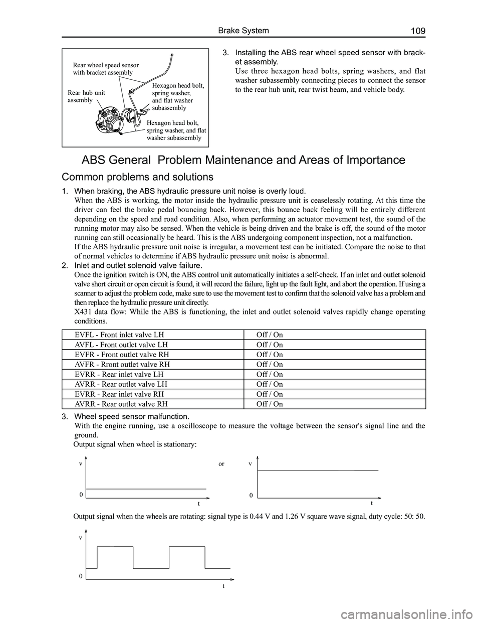
3. Installing the ABS rear wheel speed sensor with brack-
et assembly.
Use three hexagon head bolts, spring washers, and flat
washer subassembly connecting pieces to connect the sensor
to the rear hub unit, rear twist beam, and vehicle body.
ABS General Problem Maintenance and Areas of Importance
Common problems and solutions
1. When braking, the ABS hydraulic pressure unit noise is overly loud.
When the ABS is working, the motor inside the hydraulic pressure unit is ceaselessly rotating. At this time the
driver can feel the brake pedal bouncing back. However, this bounce back feeling will be entirely different
depending on the speed and road condition. Also, when performing an actuator movement test, the sound of the
running motor may also be sensed. When the vehicle is being driven and the brake is off, the sound of the motor
running can still occasionally be heard. This is the ABS undergoing component inspection, not a malfunction.
If the ABS hydraulic pressure unit noise is irregular, a movement test can be initiated. Compare the noise to that
of normal vehicles to determine if ABS hydraulic pressure unit noise is abnormal.
2. Inlet and outlet solenoid valve failure.
Once the ignition switch is ON, the ABS control unit automatically initiates a self-check. If an inlet and outlet solenoid
valve short circuit or open circuit is found, it will record the failure, light up the fault light, and abort the operation. If using a
scanner to adjust the problem code, make sure to use the movement test t\
o confirm that the solenoid valve has a problem and
then replace the hydraulic pressure unit directly.
X431 data flow: While the ABS is functioning, the inlet and outlet solenoid valves rapidly change operating
conditions.
EVFL - Front inlet valve LHOff / On
AVFL - Front outlet valve LHOff / On
EVFR - Front outlet valve RHOff / On
AVFR - Rront outlet valve RHOff / On
EVRR - Rear inlet valve LHOff / On
AVRR - Rear outlet valve LHOff / On
EVRR - Rear inlet valve RHOff / On
AVRR - Rear outlet valve RHOff / On
3. Wheel speed sensor malfunction.
With the engine running, use a oscilloscope to measure the voltage between the sensor's signal line and the
ground.
Output signal when wheel is stationary:
Output signal when the wheels are rotating: signal type is 0.44 V and 1.26 V square wave signal, duty cycle: 50: 50.
Rear hub unit assembly
Rear wheel speed sensor with bracket assembly
Hexagon head bolt, spring washer, and flat washer subassembly
Hexagon head bolt, spring washer, and flat washer subassembly
0
v
t
vv
0 0
tt
or
Page 117 of 281
Downloaded from www.Manualslib.com manuals search engine GWFLORID Maintenance Manual110
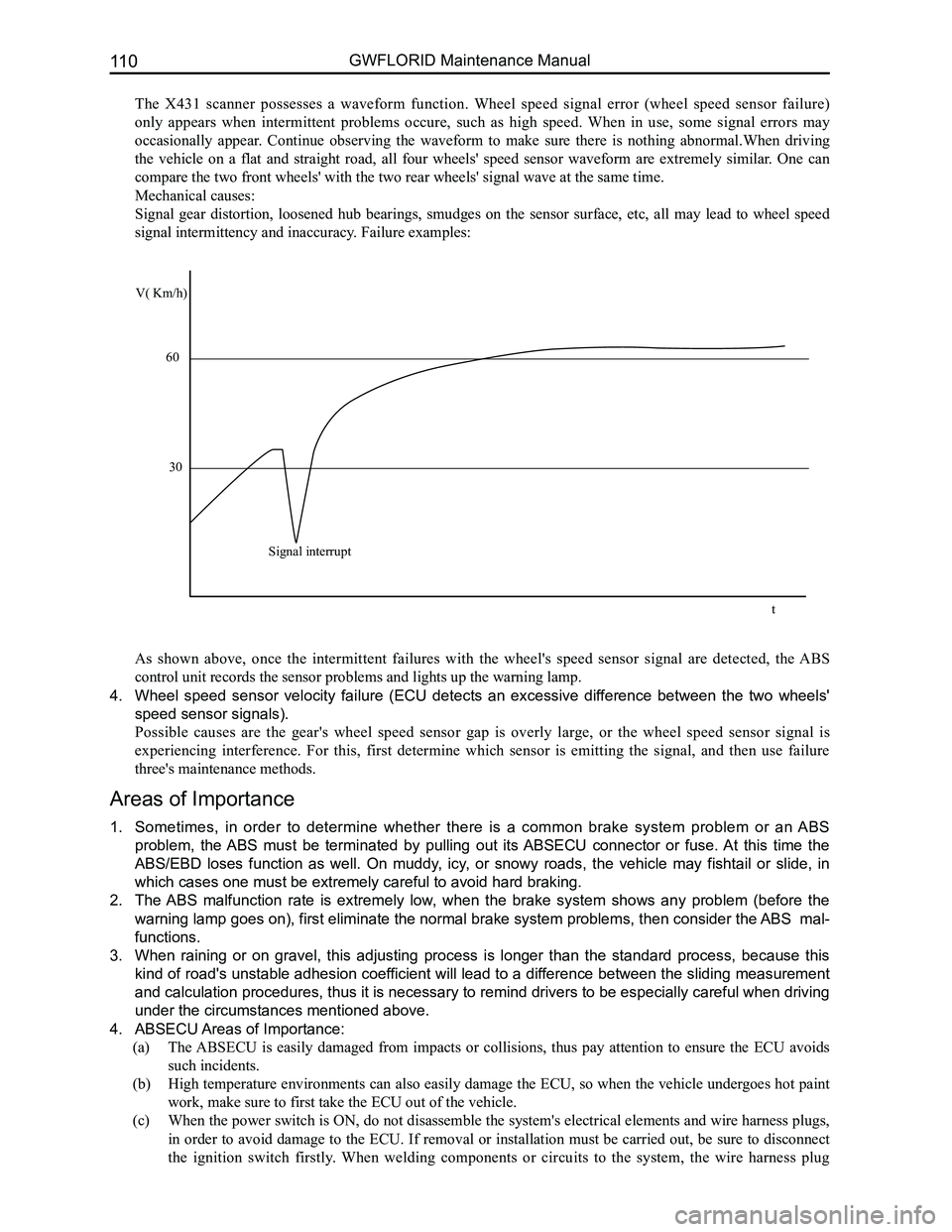
The X431 scanner possesses a waveform function. Wheel speed signal error (wheel speed sensor failure)
only appears when intermittent problems occure, such as high speed. When in use, some signal errors may
occasionally appear. Continue observing the waveform to make sure there is nothing abnormal.When driving
the vehicle on a flat and straight road, all four wheels' speed sensor waveform are extremely similar. One can
compare the two front wheels' with the two rear wheels' signal wave at t\
he same time.
Mechanical causes:
Signal gear distortion, loosened hub bearings, smudges on the sensor surface, etc, all may lead to wheel speed
signal intermittency and inaccuracy. Failure examples:
As shown above, once the intermittent failures with the wheel's speed sensor signal are detected, the ABS
control unit records the sensor problems and lights up the warning lamp.\
4. Wheel speed sensor velocity failure (ECU detects an excessive difference between the two wheels'
speed sensor signals).
Possible causes are the gear's wheel speed sensor gap is overly large, or the wheel speed sensor signal is
experiencing interference. For this, first determine which sensor is emitting the signal, and then use failure
three's maintenance methods.
Areas of Importance
1. Sometimes, in order to determine whether there is a common brake system problem or an ABS
problem, the ABS must be terminated by pulling out its ABSECU connector or fuse. At this time the
ABS/EBD loses function as well. On muddy, icy, or snowy roads, the vehicle may fishtail or slide, in
which cases one must be extremely careful to avoid hard braking.
2. The ABS malfunction rate is extremely low, when the brake system shows any problem (before the
warning lamp goes on), first eliminate the normal brake system problems, then consider the ABS mal-
functions.
3. When raining or on gravel, this adjusting process is longer than the standard process, because this
kind of road's unstable adhesion coefficient will lead to a difference between the sliding measurement
and calculation procedures, thus it is necessary to remind drivers to be especially careful when driving
under the circumstances mentioned above.
4. ABSECU Areas of Importance:
(a) The ABSECU is easily damaged from impacts or collisions, thus pay attention to ensure the ECU avoids
such incidents.
(b) High temperature environments can also easily damage the ECU, so when the vehicle undergoes hot paint
work, make sure to first take the ECU out of the vehicle.
(c) When the power switch is ON, do not disassemble the system's electrical elements and wire harness plugs,
in order to avoid damage to the ECU. If removal or installation must be carried out, be sure to disconnect
the ignition switch firstly. When welding components or circuits to the system, the wire harness plug
V( Km/h)
60
30
Signal interrupt
t
Page 150 of 281
Downloaded from www.Manualslib.com manuals search engine 143Vehicle Body Electronic System
Basic Information on the Electrical System
Electrical system schematics reading instructions
1. Configuration introduction
The GWFLORID comes in three configurations: comfort, luxury and elite. The wire harness has two types of
configurations: One is a non jam protection comfort model, which is a combination of both comfort and luxury
type, the other type is called elite. These two configurations are universally used in most of this manual. The
parts that are only available for the non jam protection comfort type have been marked in this manual, please
pay attention to these sections while performing maintenance.
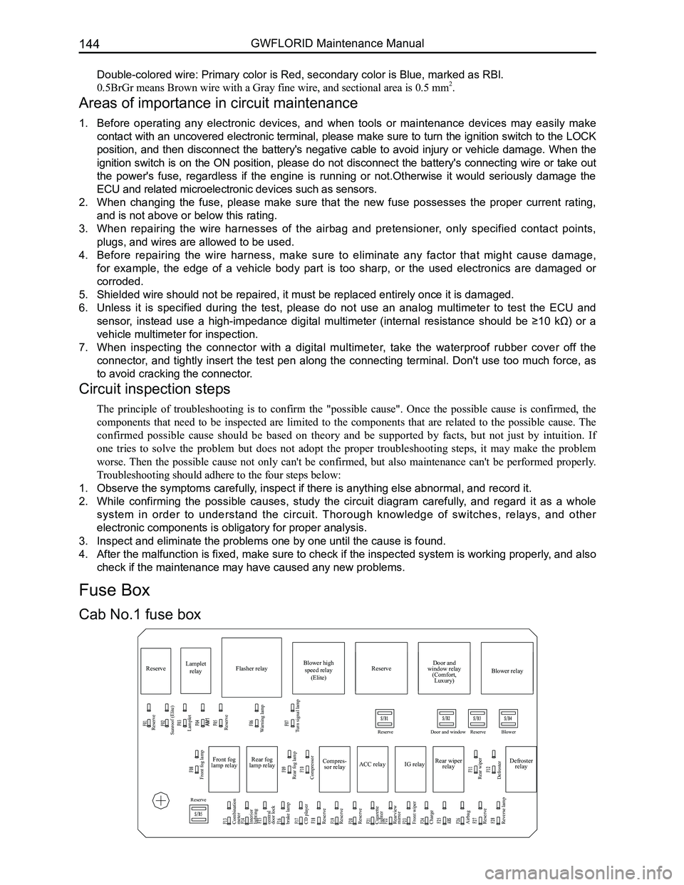
2. Fuse box and power supply introduction
The fuse box located inside the left side of the dashboard is No. 1 Fuse Box, the other one inside the left side of
the engine compartment is No. 2 Fuse Box.
• 30 represents a power cord for normal power, which is from the battery positive fuse box-60 A.
• 30a represents a power cord for normal power, which is from the battery positive fuse box-120 A.
• 30b represents a power cord for normal power, which is from the battery positive fuse box-120 A.
• 15 represents a power cord for small capacity electronics. When the ignition switch is at the "ON" position,
power is supplied by relay IG.
• 15a represents a power cord for small capacity electronics. When the ignition switch is at the "ON"
position, power is directly supplied by ignition switch IG1.
• 15b represents a power cord for small capacity electronics. When the ignition switch is at the "ON"
position, power is directly supplied by ignition switch IG2.
• X represents a power cord for small capacity electronics. When the ignition switch is at the "ACC"
position, power is supplied by relay ACC.
4. Wire's color and sectional area (mm2)
B-BlackW-WhiteR-RedBl-BlueBr-BrownY-Yellow
G-GreenP-PinkOr-OrangeV-VioletLg-Light greenGr-Gray
Mark the solid-colored wires with the letters in the above table. Double-colored wires' first letter is the primary
color, second letter is the secondary color.
For example:
Solid-colored wire: Red, marked as R.
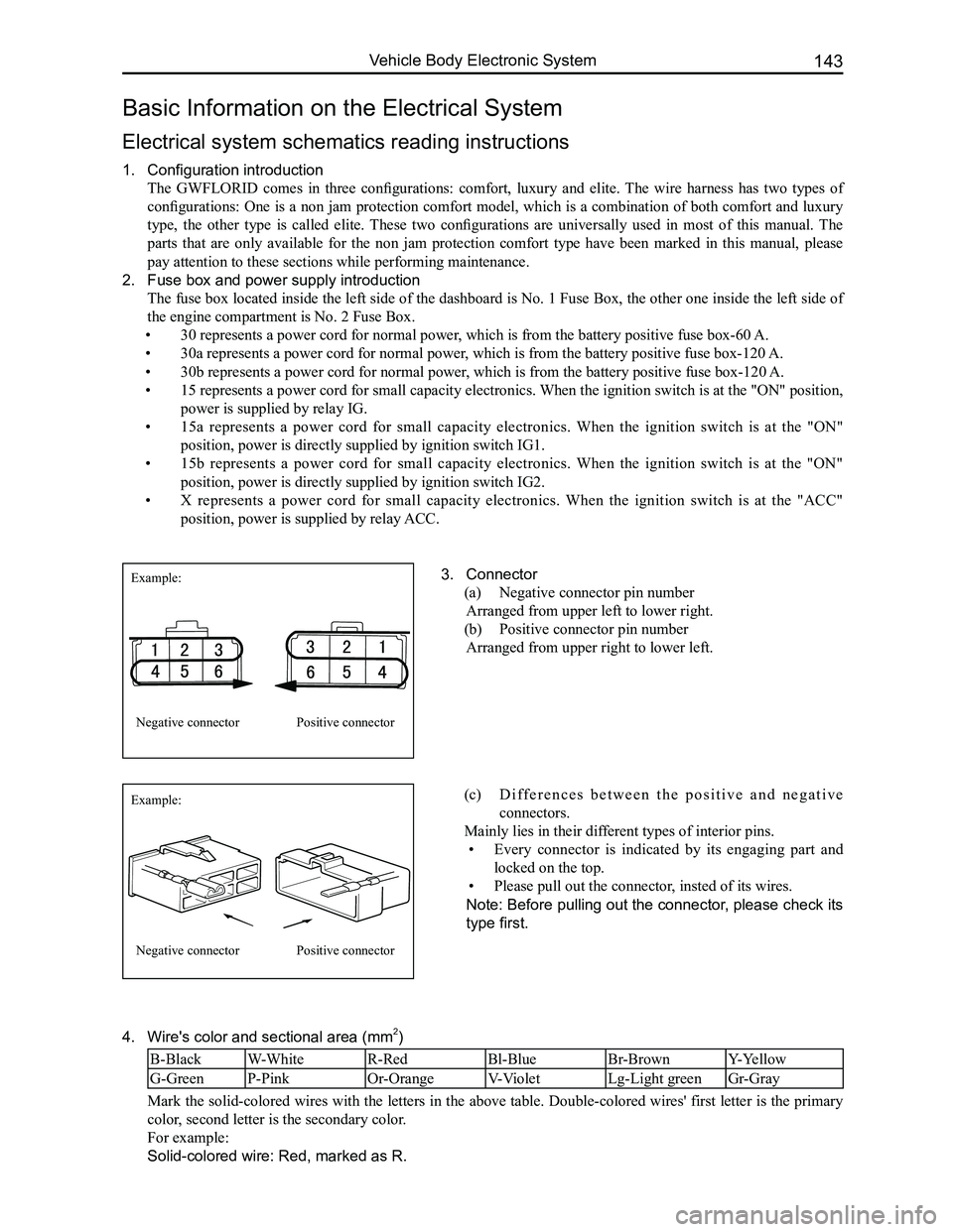
3. Connector
(a) Negative connector pin number
Arranged from upper left to lower right.
(b) Positive connector pin number
Arranged from upper right to lower left.
Example:
Example:
Negative connector
Negative connector
Positive connector
Positive connector
(c) D i f f e r e n c e s b e t w e e n t h e p o s i t i v e a n d n e g a t i v e
connectors.
Mainly lies in their different types of interior pins.
• Every connector is indicated by its engaging part and
locked on the top.
• Please pull out the connector, insted of its wires.
Note: Before pulling out the connector, please check its
type first.
Page 151 of 281
Downloaded from www.Manualslib.com manuals search engine GWFLORID Maintenance Manual144
Double-colored wire: Primary color is Red, secondary color is Blue, mark\
ed as RBl.
0.5BrGr means Brown wire with a Gray fine wire, and sectional area is 0.\
5 mm2.
Areas of importance in circuit maintenance
1. Before operating any electronic devices, and when tools or maintenance devices may easily make
contact with an uncovered electronic terminal, please make sure to turn the ignition switch to the LOCK
position, and then disconnect the battery's negative cable to avoid injury or vehicle damage. When the
ignition switch is on the ON position, please do not disconnect the battery's connecting wire or take out
the power's fuse, regardless if the engine is running or not.Otherwise it would seriously damage the
ECU and related microelectronic devices such as sensors.
2. When changing the fuse, please make sure that the new fuse possesses the proper current rating,
and is not above or below this rating.
3. When repairing the wire harnesses of the airbag and pretensioner, only specified contact points,
plugs, and wires are allowed to be used.
4. Before repairing the wire harness, make sure to eliminate any factor that might cause damage,
for example, the edge of a vehicle body part is too sharp, or the used electronics are damaged or
corroded.
5. Shielded wire should not be repaired, it must be replaced entirely once it is damaged.
6. Unless it is specified during the test, please do not use an analog multimeter to test the ECU and
sensor, instead use a high-impedance digital multimeter (internal resistance should be ≥10 kΩ) or a
vehicle multimeter for inspection.
7. When inspecting the connector with a digital multimeter, take the waterproof rubber cover off the
connector, and tightly insert the test pen along the connecting terminal. Don't use too much force, as
to avoid cracking the connector.
Circuit inspection steps
The principle of troubleshooting is to confirm the "possible cause". Once the possible cause is confirmed, the
components that need to be inspected are limited to the components that are related to the possible cause. The
confirmed possible cause should be based on theory and be supported by facts, but not just by intuition. If
one tries to solve the problem but does not adopt the proper troubleshooting steps, it may make the problem
worse. Then the possible cause not only can't be confirmed, but also maintenance can't be performed properly.
Troubleshooting should adhere to the four steps below:
1. Observe the symptoms carefully, inspect if there is anything else abnormal, and record it.
2. While confirming the possible causes, study the circuit diagram carefully, and regard it as a whole
system in order to understand the circuit. Thorough knowledge of switches, relays, and other
electronic components is obligatory for proper analysis.
3. Inspect and eliminate the problems one by one until the cause is found.
4. After the malfunction is fixed, make sure to check if the inspected system is working properly, and also
check if the maintenance may have caused any new problems.
Compres-
sor relay
Reserve
Sunroof (Elite) Lamplet
Reserve
Reserve
Reserve
Reserve Door and window Reserve Blower
Lamplet
relay Flasher relay Blower high
speed relay (Elite) Door and
window relay (Comfort, Luxury) Blower relay
Reserve
Front fog lamp
Combination
meter
Interior
lighting
central
door lock
brake lamp
CD player
Reserve
Reserve
Reserve
Cigarette
lighter
Rearview
mirror
Front wiper
Charge
Airbag
Reserve
Reverse lamp Rear fog lamp
Rear wiper
Defroster Compressor
ACC relay
IG relayRear wiper
relay Defroster
relay
Front fog
lamp relay Rear fog
lamp relay
Warning lamp
Turn signal lamp
Cab No.1 fuse box
Fuse Box