Page 25 of 419

FuelFuel systemPrecautions1. Before repairing fuel system, uncouple battery negative (-) wire at first.
2. When operating on fuel system, do not smoke or repair near fire area.
3. Do not let gasoline come into contact with rubber or leather parts.
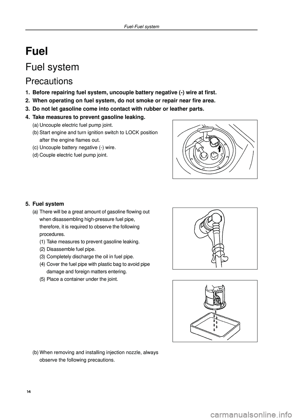
4. Take measures to prevent gasoline leaking.(a) Uncouple electric fuel pump joint.
(b) Start engine and turn ignition switch to LOCK position
after the engine flames out.
(c) Uncouple battery negative (-) wire.
(d) Couple electric fuel pump joint.5. Fuel system(a) There will be a great amount of gasoline flowing out
when disassembling high-pressure fuel pipe,
therefore, it is required to observe the following
procedures.
(1) Take measures to prevent gasoline leaking.
(2) Disassemble fuel pipe.
(3) Completely discharge the oil in fuel pipe.
(4) Cover the fuel pipe with plastic bag to avoid pipe
damage and foreign matters entering.
(5) Place a container under the joint.
(b) When removing and installing injection nozzle, always
observe the following precautions.Fuel-Fuel system 14
Page 26 of 419

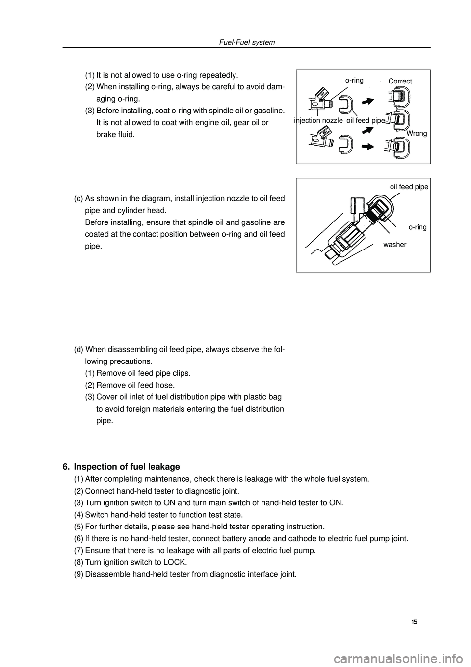
Fuel-Fuel system(1) It is not allowed to use o-ring repeatedly.
(2) When installing o-ring, always be careful to avoid dam-
aging o-ring.
(3) Before installing, coat o-ring with spindle oil or gasoline.
It is not allowed to coat with engine oil, gear oil or
brake fluid.
(c) As shown in the diagram, install injection nozzle to oil feed
pipe and cylinder head.
Before installing, ensure that spindle oil and gasoline are
coated at the contact position between o-ring and oil feed
pipe.
(d) When disassembling oil feed pipe, always observe the fol-
lowing precautions.
(1) Remove oil feed pipe clips.
(2) Remove oil feed hose.
(3) Cover oil inlet of fuel distribution pipe with plastic bag
to avoid foreign materials entering the fuel distribution
pipe.injection nozzle6. Inspection of fuel leakage(1) After completing maintenance, check there is leakage with the whole fuel system.
(2) Connect hand-held tester to diagnostic joint.
(3) Turn ignition switch to ON and turn main switch of hand-held tester to ON.
(4) Switch hand-held tester to function test state.
(5) For further details, please see hand-held tester operating instruction.
(6) If there is no hand-held tester, connect battery anode and cathode to electric fuel pump joint.
(7) Ensure that there is no leakage with all parts of electric fuel pump.
(8) Turn ignition switch to LOCK.
(9) Disassemble hand-held tester from diagnostic interface joint.15o-ringoil feed pipeoil feed pipeo-ringwasherCorrect
Wrong
Page 32 of 419

Fuel - Fuel tank assemblyFuel tank assembly1. Take measures to prevent gasoline leaking
(see Page 14)
2. Remove rear seat cushion assembly
3. Remove rear floor repairing hole cover
4. Remove No. 2 fuel evaporation assembly
5. Remove fuel tank main fuel hose and oil return pipe
assembly
6. Remove fuel pump assembly
7. Discharge fuel
8. Remove front floor bracket
9. Remove front exhaust pipe assembly(a) Move away carpet and remove oxygen sensor joint.
(b) Remove front exhaust pipe assembly10.Disassemble the vent pipe of fuel hose
11.Disassemble filler pipe from fuel tank
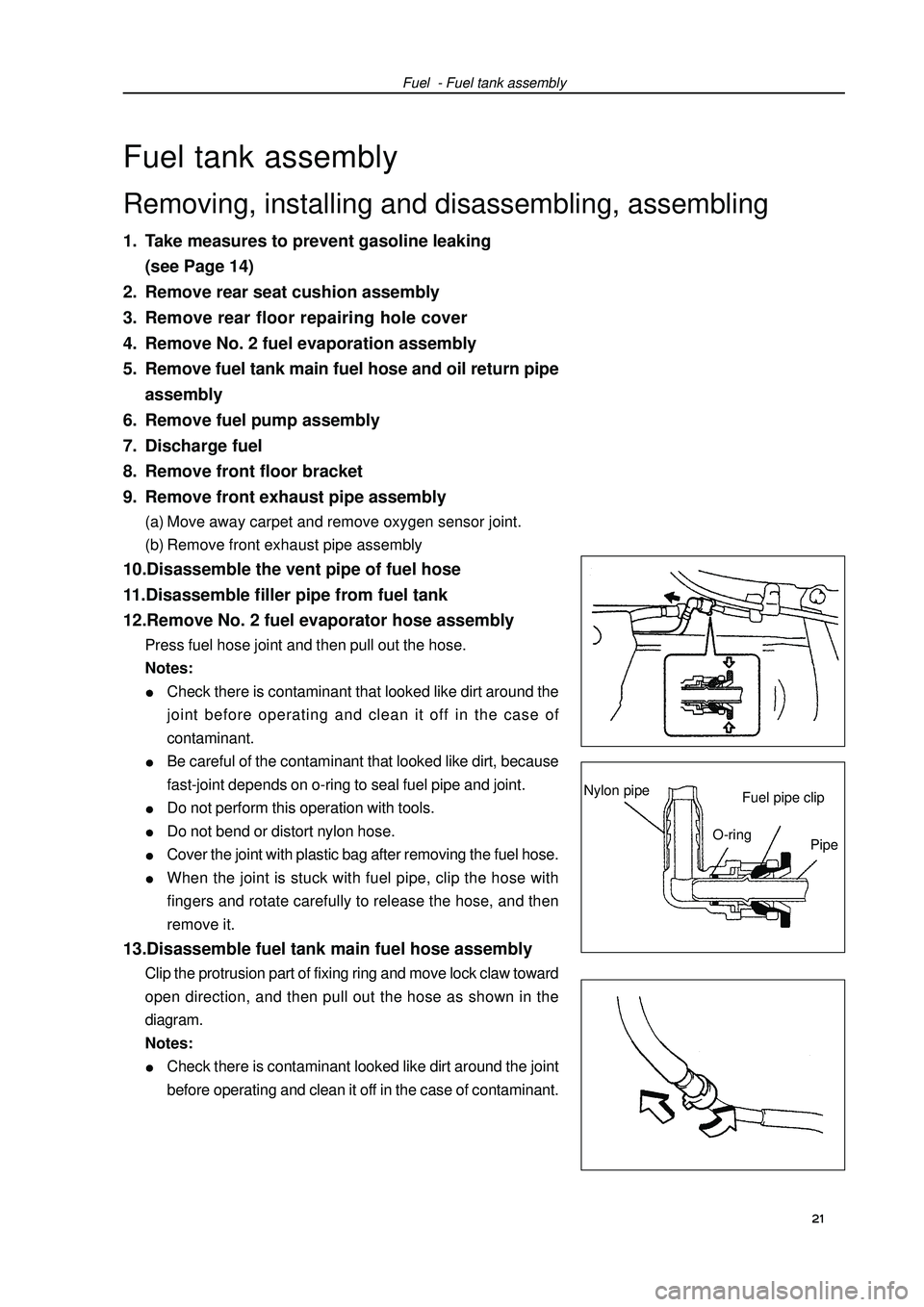
12.Remove No. 2 fuel evaporator hose assemblyPress fuel hose joint and then pull out the hose.
Notes:Check there is contaminant that looked like dirt around the
joint before operating and clean it off in the case of
contaminant.Be careful of the contaminant that looked like dirt, because
fast-joint depends on o-ring to seal fuel pipe and joint.Do not perform this operation with tools.Do not bend or distort nylon hose.Cover the joint with plastic bag after removing the fuel hose.When the joint is stuck with fuel pipe, clip the hose with
fingers and rotate carefully to release the hose, and then
remove it.13.Disassemble fuel tank main fuel hose assemblyClip the protrusion part of fixing ring and move lock claw toward
open direction, and then pull out the hose as shown in the
diagram.
Notes:Check there is contaminant looked like dirt around the joint
before operating and clean it off in the case of contaminant. 21 Removing, installing and disassembling, assemblingFuel pipe clipNylon pipeO-ring
Pipe
Page 39 of 419
Engine mechanism - Engine assemblyCO HC Trouble occurrence Possible causes 28 Normal HighUnstable idle speed
Low HighUnstable idle speed
(HC readings not stable)
High HighUnstable idle speed
(black smoke emission)1. Ignition system malfunctionIgnition timing incorrect Spark plug too dirty, short circuit or clearance
incorrect
2. Valve clearance incorrect
3. Air inlet and exhaust valve leaky
4. Cylinder leaky
1. Vacuum leak:PCV hoseIntake manifoldThrottle bodyIdle speed stepping motorVacuum booster and pipelines
2. Fire caused by too thin mixing ratio
1. Air filter core blocked
2. PCV valve blocked
3. EFI system malfunctionFuel pressure regulator malfunctionWater temperature sensor malfunctionIntake pressure sensor malfunctionECU malfunctionInjection nozzle malfunctionThrottle position sensor malfunction
Page 40 of 419
Engine mechanism - Drive beltDrive beltReplacement1. Remove engine right bottom shield.
2. Remove drive beltSlowly turn drive belt tensioner clockwise to loosen it.
Then remove drive belt and put back drive belt tensioner slowly
and gently.3. Install drive beltSlowly turn drive belt tensioner clockwise to loosen it.
Then install drive belt and put back drive belt tensioner slowly
and gently.29
Page 41 of 419
![GEELY FC 2008 Workshop Manual Engine mechanism - Valve clearanceValve clearanceAdjustment1. Remove engine plastic hood components.
2. Remove ignition coil components [4G18-3705110].
3. Remove cylinder head cover components [4G18-
GEELY FC 2008 Workshop Manual Engine mechanism - Valve clearanceValve clearanceAdjustment1. Remove engine plastic hood components.
2. Remove ignition coil components [4G18-3705110].
3. Remove cylinder head cover components [4G18-](/manual-img/58/57161/w960_57161-40.png)
Engine mechanism - Valve clearanceValve clearanceAdjustment1. Remove engine plastic hood components.
2. Remove ignition coil components [4G18-3705110].
3. Remove cylinder head cover components [4G18-
1003130].
4. Remove engine right bottom shield.
5. Turn crankshaft to cylinder 1 compression top dead
center position.(a) Turn crankshaft pulley to align its groove with “o” mark on
timing chain hood.
(b) Check dot marks on camshaft timing sprocket and VVT
timing sprocket, and they should be in a line on timing chain
hood surface as shown in the diagram.
Hint: if not, turn crankshaft for one circle again
and align the above marks.6. Check valve clearance.(a) Only check the valves shown in the diagram.
(1) Measure the clearance between valve tappet and cam-
shaft with plug gauge.
(2) Record valve clearance measuring value exceeding
specification, and this value will be used to determine
valve tappet thickness that needs change.
Valve clearance (cold vehicle)Intake airExhaust(b) Turn crankshaft for one circle ), and cylinder 4 is
turned to compression top dead center position.
(c) Only check the valves shown in the diagram. Measure valve
clearance (see step (a)).7. Remove drive beltSlowly turn drive belt tensioner clockwise to loosen it.
Then remove drive belt and put back drive belt tensioner slowly
and gently. 30 Mark
Mark
Mark
Timing chain
hood surface
Groove
Page 42 of 419

Engine mechanism - Valve clearance8. Remove right engine mounting assembly(a) Remove PS oil pump reservoir and put it aside.
(b) Place wooden block between jack and engine, properly
place the jack, and then remove right engine mounting
assembly.9. Remove drive belt tensioner device [4G18-
1300200].Hint: operate the jack up and down to remove bolts.10. Adjust valve clearance.Note: do not turn crankshaft before installing chain
tensioner.
(a) Turn crankshaft to cylinder 1 top dead center position.
(b) Align the marks on timing chain and camshaft timing
sprocket.
(c) Remove 2 bolts and chain tensioner.
(d) Fix camshaft with adjustable wrench and then loosen
the fixed bolts of exhaust camshaft timing sprocket.
Note: be careful not to damage valve lifter.
(e) As sequences shown in the diagram, loosen camshaft
bearing cover bolts on exhaust camshaft at several
times and remove the bearing cover at the same time.
(f) As shown in the diagram, remove exhaust camshaft
timing sprocket.Painting
mark
LooseningFixing 31
Page 44 of 419
Engine mechanism - Valve clearance(n) Check intake side camshaft bearing cover forward re-
mark and figure, and tighten the bolts as sequences
shown in the diagram.
Torque: (o) Align alignment mark on the chain with timing mark on
camshaft timing sprocket, and place exhaust camshaft
in cylinder head.
(p) Temporarily lock fixed bolts.
(q) Check exhaust side camshaft bearing cover forward
remark and figure, and tighten the bolts as sequences
shown in the diagram.
Torque: (r) Install camshaft front bearing cover.
Torque: (s) Fix camshaft with adjustable wrench and then tighten
the fixed bolts of camshaft timing sprocket.
Torque: Note: be careful not to damage valve lifter.33Timing remark chain linkTiming markTighteningFixing