Page 178 of 392
171Chapter 3 Combination Meter SystemSection 1 Circuit Diagram of Combination Meter and Location of
Multi-pin Plug-in TerminalI. CIRCUIT DIAGRAM OF CONBINATION METERSpeed Signal
Ground The Sensor
Revolution SignalWater Temperature SignaFuel Level GaugeTachometer
SpeedometerWater
Temperature Gauge
Feul Level Gauge
OdometerHigh Beam Lamp
Rear Defrost Lamp
Rear Defog Lamp
Backlight
Water Temperature WarningPower Steering
Fuel WarningCharge
Brake Fluid
Oil Pressure
Engine Malfunction
Driver's seat belt
Park Brake
SRS(main)
SRS(sub)
Page 180 of 392
1732. DEFINITION OF MULTIPIN PLUG-IN TERMINALDefinition of Terminal Color of Harness
1Empty
2EPS VG
3Empty
4Empty
5Empty
6Empty
7Empty
8 Combination switch (Position lamp P
9 Speed sensor groun B
10 Speed sensor power sourc RY
11 Speed sensor signal outpu YR
12 Fuel senso B
13 Alte rna tor WR
14 Brake fluid level switc GR
15 Oil pressure switc YG
16 Re a r de frost YB
1 Rear fog lamp Gr
2 Engine ma lfunc tion GY
3 S e a t be lt s w it c h R
4 P owe r sourc e Y
5 Engine coolant temperature senso YW
6 Park switch G
7 Power source groun B
8 Power source groun B
9ABS R
10 SRS (Ma in) RY
11 Engine re volution signa l BBl
12 Live wire (Fire wire) WG
13 High be am la mp + RB
14 Low bea m - RW
15 SRS (Sub) RG
16 Empty Terminal No.
A
B
Page 192 of 392
1855. FUEL GAUGE MALFUNCTION
CIRCUIT DIAGRAM
(a) Inspect the combination meter assembly
1Inspect resistance
�yRemove the combination meter assembly and disconnect connectors
�yInspect continuity between terminals
Standard:
Result and solution:
NormalReplace the combination meter assembly
If abnormal inspect the fuel level sensor
2Inspect the fuel level sensor
�yRemove the fuel level sensor
�yAdjust the height of the fuel level sensor and measure its resistance.Te ster connec tionC ondit ionSta ndard c onditionE110±6Ω
1/2 32.5±3Ω
F3±2Ω A12 - groundFuel Level SensorCombined Meter Assembly
Fuel Signal
Page 193 of 392
186Standard:
Result and solution:
Normal:Repair or replace the harness and connector
If abnormal replace the fuel level sensor
6. THE OTHER INDICATORS
Short the ports of the other indicators respectively to the ground or power source in accordance with the
Circuit Diagram, the indicators will light correspondingly. If it dose not light, replace the combination meter.
If it lights, repair or replace the harness or connector.
7. ODOMETER MALFUNCTION
Inspect first supposing the problem to be from the speedometer. If the speedometer is normal, the combina-
tion meter needs replacing when the odometer is abnormal.Condition Standa rd condition
E 110±6Ω
1/2 32.5±3Ω
F3±2Ω
Page 197 of 392
190Analog Meter
4. INSPECT FUEL LEVEL GAUGE
(1) Inspect resistance
When the fuel level gauge indicates no fuel, inspect the resistance between terminal A-12 and B-7 on the
combination meter connector.
Standard:
NOTICE:
Connector should be disconnected when measured.
5. INSPECT WATER TEMPERATURE GAUGE
(1) Inspect resistance
When the water temperature is indicated in the red area, inspect the resistance between terminal B-5 and
B-7 on the combination meter connector.Ta c home te r (r/min) handy tac home te r (r/min)
800 740—860
1000 900—1100
2000 1850—2150
3000 2800—3200
4000 3800—4200
5000 4800—5200
6000 5750—6250Sta ndard indic a tion Re sista nc e (Ω)
E 104—116
Warning point 90—100
1/2F 29—35
F1
—5
Page 220 of 392

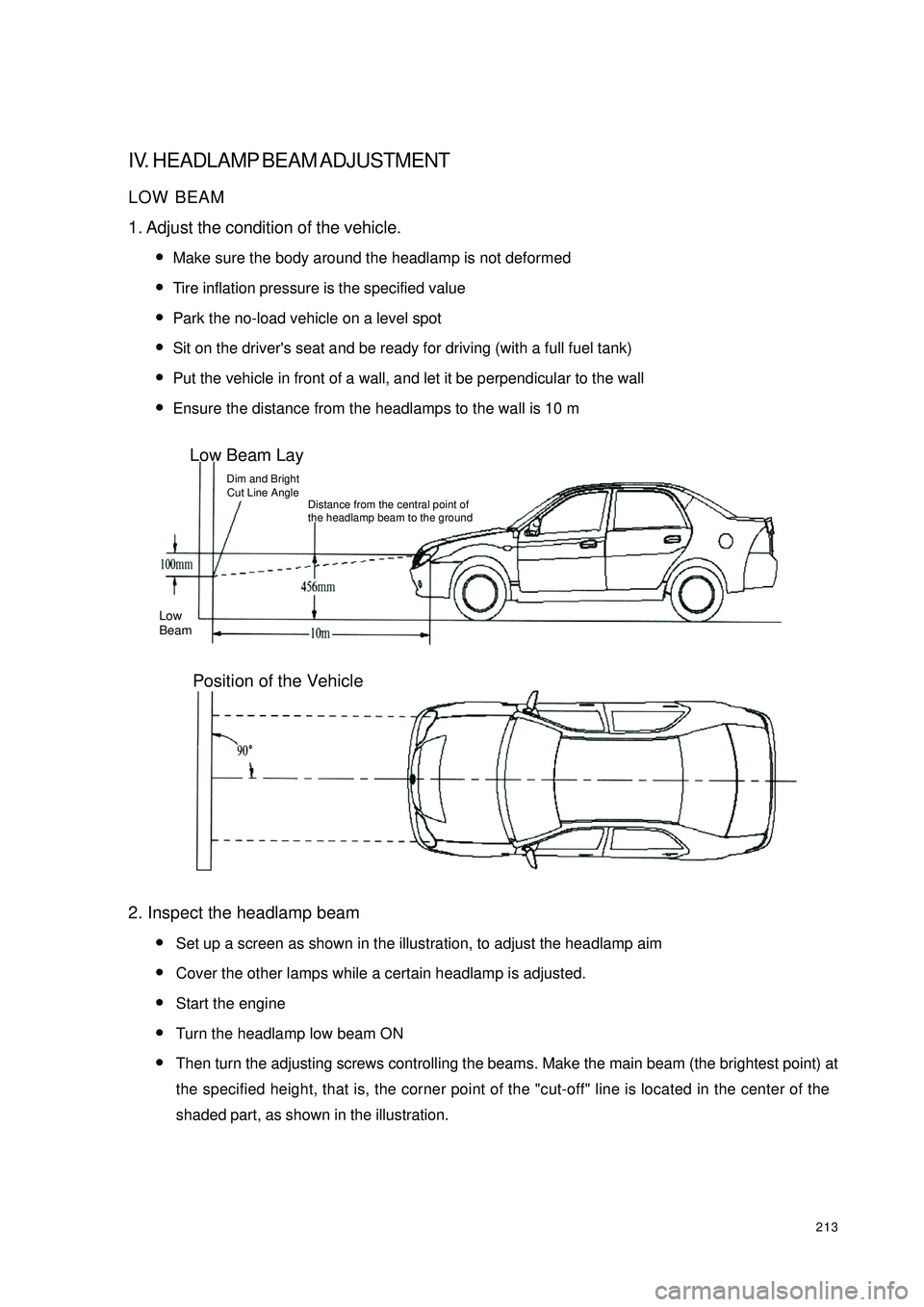
213IV. HEADLAMP BEAM ADJUSTMENTLOW BEAM
1. Adjust the condition of the vehicle.
�yMake sure the body around the headlamp is not deformed
�yTire inflation pressure is the specified value
�yPark the no-load vehicle on a level spot
�ySit on the driver's seat and be ready for driving (with a full fuel tank)
�yPut the vehicle in front of a wall, and let it be perpendicular to the wall
�yEnsure the distance from the headlamps to the wall is 10 m
2. Inspect the headlamp beam
�ySet up a screen as shown in the illustration, to adjust the headlamp aim
�yCover the other lamps while a certain headlamp is adjusted.
�yStart the engine
�yTurn the headlamp low beam ON
�yThen turn the adjusting screws controlling the beams. Make the main beam (the brightest point) at
the specified height, that is, the corner point of the "cut-off" line is located in the center of the
shaded part, as shown in the illustration.Low Beam LayDim and Bright
Cut Line AngleDistance from the central point of
the headlamp beam to the groundLow
BeamPosition of the Vehicle
Page 325 of 392
318Chapter 2 Inside & outside Trim and AccessorySection 1 Configuration Index(I) Outside Trim And Front Accessory1 Door handle 6 Windshield
Front fender
(See the engine hood adjustment)
Front bumper
(See front bumper
r em o v a l/ in s t allat io n )
The engine hood
(See the engine hood
r em o v a l/ in s t a llat io n )
Elec tric outs ide rear view mirror
(See elec tric outs ide rear view
m ir r o r r em o v a l/ in s t allat io n ) 5 Co w l v e n t g r ille 1 0Front mudguard skirt
4 9 Fuel fill port cap 2 Ra d ia t o r g r ill a s s em b ly 7
38