Page 138 of 392
131Replacement1. Cautions (refer to Steering System Cautions)
2. Make sure the wheels are placed straight ahead
3. disconnect the battery negative terminals
4. Remove the air bag assembly
Remove two screws on both sides and pull out the wiring harness connector
Notice: Do not pull air bag wire harness when removing the air bag assembly!
Warning:
�‹ �‹�‹ �‹
�‹Make sure the upper surface of the air bag assembly is kept upward when placing it!
�‹ �‹�‹ �‹
�‹Do not disassemble the air bag assembly!
5. Remove steering wheel assembly
(1) Remove the nut.
(2) Remove the steering wheel cover set bolt.
(3) place the matchmarks on the steering wheel and main shaft assembly.
(4) Use special tool to remove the steering wheel assembly.
6. Remove the steering column upper and lower cover
(1) Remove 3 screws.
(2) Remove the steering column upper and lower cover.Use Inner
Hex Socket
Wrench
Page 164 of 392

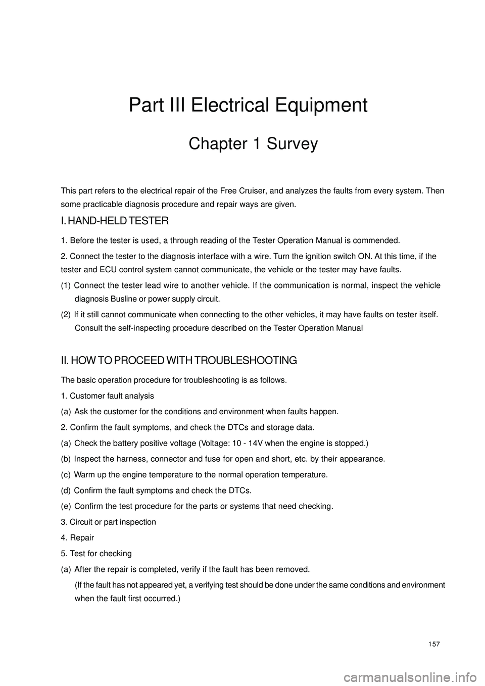
157Part III Electrical EquipmentChapter 1 SurveyThis part refers to the electrical repair of the Free Cruiser, and analyzes the faults from every system. Then
some practicable diagnosis procedure and repair ways are given.I. HAND-HELD TESTER1. Before the tester is used, a through reading of the Tester Operation Manual is commended.
2. Connect the tester to the diagnosis interface with a wire. Turn the ignition switch ON. At this time, if the
tester and ECU control system cannot communicate, the vehicle or the tester may have faults.
(1) Connect the tester lead wire to another vehicle. If the communication is normal, inspect the vehicle
diagnosis Busline or power supply circuit.
(2) If it still cannot communicate when connecting to the other vehicles, it may have faults on tester itself.
Consult the self-inspecting procedure described on the Tester Operation ManualII. HOW TO PROCEED WITH TROUBLESHOOTINGThe basic operation procedure for troubleshooting is as follows.
1. Customer fault analysis
(a) Ask the customer for the conditions and environment when faults happen.
2. Confirm the fault symptoms, and check the DTCs and storage data.
(a) Check the battery positive voltage (Voltage: 10 - 14V when the engine is stopped.)
(b) Inspect the harness, connector and fuse for open and short, etc. by their appearance.
(c) Warm up the engine temperature to the normal operation temperature.
(d) Confirm the fault symptoms and check the DTCs.
(e) Confirm the test procedure for the parts or systems that need checking.
3. Circuit or part inspection
4. Repair
5. Test for checking
(a) After the repair is completed, verify if the fault has been removed.
(If the fault has not appeared yet, a verifying test should be done under the same conditions and environment
when the fault first occurred.)
Page 168 of 392
161Chapter 2 Starting and Charging SystemSection 1 Starting System
(MR479Q MR479QA MR481QA)I. STARTER INSPECTIONNOTICE:
These tests must be done within 5 seconds to avoid burning out the coil.
1. INSPECT MAGNETIC SWITCH
(a) Use wire to connect the starter as shown.
(b) Connect the magnetic switch and the battery as
shown.
(c) Disconnect the magnet exciting coil from the
terminal A.
(d) Check if the clutch pinion gear is moving out.
If the clutch pinion gear is not moving out, replace
the magnetic switch.
(e) Connect the battery as shown above. Disconnect
the battery positive (+) from the terminal, to make the clutch pinion gear disengaged.
(f) Check if the clutch pinion gear has returned.
If the clutch pinion gear has not returned, replace
the magnetic switch.Terminal ABatteryBatteryDisconnect
Page 169 of 392
1622. INSPECT STARTER NO-LOAD
(a) Connect the magnet exciting coil and the terminal.
(b) Connect the ammeter and the battery to the starter
as shown.
(c) Check that the starter rotates smoothly and steadily
with the clutch pinion gear moving out.
(d) Check that the ammeter shows the specified
current.
Specified current: 90 A or less at 11.5 V
if the current is not normal, replace the starter.
3. WIRING
(a) Check that the connecting wire between
the positive (+) and the starter is stable
and reliable, and the insulating bush is in
good condition, in order to avoid a fire
caused by electric spark.
(b) Check that there is continuity in the wire
and if the insulating bush is not damaged.
If the harness is damaged, replace it.AmmeterIgnition SwitchBattery Main Fuse BoxStarter
Page 171 of 392
164Section 2 Charging System
(MR479Q, MR479QA, MR481QA)I. BATTERYMaintenance-free battery is applied in this vehicle. Its termination voltage is 12V. It is connected inline by six
2V single cell in tandem with walls between every pole.
1. BATTERY WARNING SIGNS
1 -- Danger of corrosion
The battery electrolyte is very corrosive. DO NOT overturn the battery.
2 -- Read the instructions for battery
3 -- Children are forbidden to touch the battery
4 -- Avoid fire, electromagnetic wave and strong light.
Avoid electric spark while repair; avoid short.
5 -- Wear protecting glasses
6 -- Danger of explosion
The explosive mixed gas will be produced while charging.
7 -- How to deal with a scrapped battery
The scrapped battery should be delivered to the collection station.1234567
Page 172 of 392
1652. BATTERY REMOVAL AND INSTALLATION
HINT:
(1) The battery is not allowed to contact lubricating grease.
(2) The battery terminal is only allowed to be softly pulled out, in order to void damaging the battery.REMOVAL(1) Remove the negative (-) ground cable
(2) Remove the battery positive (+) cable
(3) Loosen the fixing clamp on the battery.INSTALLATIONInstall according to the inverted order of removal.
Tighten the torque
Tighten the battery cable clip to 6N.m (61kgf.cm, 4ft.lbf)
Tighten the fixing clamp to 12N.m (123kgf.cm, 8.6ft.lbf)
Page 173 of 392
166II. CHARGING SYSTEM INSPECTION1. CHECK BATTERY WORKING VOLTAGE
(a) After having driven the vehicle and in the case that 20 minutes have not passed after having stopped the
engine, turn the ignition switch ON and turn on the electrical system (headlight, blower motor) for 60
seconds to remove the surface charge.
(b) Turn the ignition switch OFF and
turn off the electrical systems. Then
measure the battery voltage
between the negative and positive
terminals of the battery.
Standard voltage: 12.5-12.9V at
20°C
HINT:
If the voltage is less than specification, charge the battery.
2. CHECK BATTERY TERMINALS, FUSE BOX AND FUSE
(a) Check that the battery terminals are not loose or corroded.
(b) Check if fuse box and fuse for continuity.
Page 175 of 392

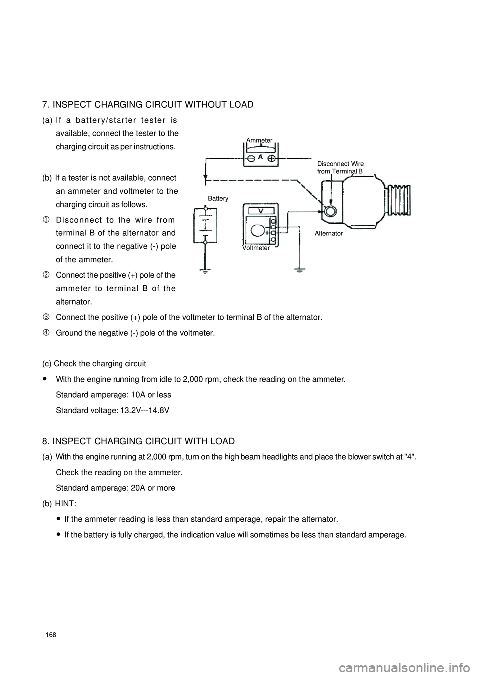
1687. INSPECT CHARGING CIRCUIT WITHOUT LOAD
(a) If a battery/starter tester is
available, connect the tester to the
charging circuit as per instructions.
(b) If a tester is not available, connect
an ammeter and voltmeter to the
charging circuit as follows.
1Disconnect to the wire from
terminal B of the alternator and
connect it to the negative (-) pole
of the ammeter.
2Connect the positive (+) pole of the
ammeter to terminal B of the
alternator.
3Connect the positive (+) pole of the voltmeter to terminal B of the alternator.
4Ground the negative (-) pole of the voltmeter.
(c) Check the charging circuit
�yWith the engine running from idle to 2,000 rpm, check the reading on the ammeter.
Standard amperage: 10A or less
Standard voltage: 13.2V---14.8V
8. INSPECT CHARGING CIRCUIT WITH LOAD
(a) With the engine running at 2,000 rpm, turn on the high beam headlights and place the blower switch at "4".
Check the reading on the ammeter.
Standard amperage: 20A or more
(b) HINT:
�yIf the ammeter reading is less than standard amperage, repair the alternator.
�yIf the battery is fully charged, the indication value will sometimes be less than standard amperage.Ammeter
Disconnect Wire
from Terminal B
Battery
VoltmeterAlternator