Page 93 of 392
86Replacement1. Remove shift lever assembly
(1) Pull upwards to separate the shift lever assembly leather boot from the auxiliary console
(2) Loosen the shift lever set screw with inner hex wrench. Remove the shift lever assembly counterclockwise
2. Remove auxiliary console
3. Remove control lever dust cover
Remove the 4 nuts on the control lever dust cover and the body.
4. Remove dust cover retainer
5. Remove control pull rod assembly
(1) Remove the pull rod connecting bolt (Place 2)
(2) Remove 2 hex flange bolts (Place 1)
(3) Remove the 2 flange nuts attaching the control pull rod to the body in the trench
6. The installation is in the reverse order of the above operation.
Notice:
(1) Pull rod (to transmission) attach bolt torque: 40~50N.m
(2) The torque of the two nuts attaching the control mechanism to the body: 20~25N.mBottom Panel
Assembly of
BodyControl Pull Rod Assembly
Transmission Assembly
Page 94 of 392
87(3) Dust cover retainer shall be assembled well, otherwise the dust seal effect will be af-
fected
(4) Dust cover fixing nut torque: 20~25N.m
(5) Make sure the shift number words on the top of shift lever ball face towards the driving
direction of the vehicle, properly tighten the set screw of the shift lever
(6) Check whether the shift control is flexible and reliable; the shift lever shall be vertical
when in neutral shift.Section 3 Cable Type Transmission Control ModuleComponentsShift Lever AssemblyE Shaped
clip plateCotter PinBig Washer Big Washer Cotter PinE Shaped clip plateTransmission
AssemblyCowl BaffleShift Control DeviceCushionBottom Panel
Assembly of Body
Page 95 of 392
88Replacement1. Remove shift lever assembly
(1) Pull upwards to separate shift lever assembly leather boot from the auxiliary console
(2) Loosen shift lever set screw with inner hex wrench. Remove the shift lever assembly counterclockwise.
2. Remove the auxiliary console
3. Remove the 4 nuts connecting manual shift assembly and the floor
4. Remove the shift cushion
5. Remove transmission control device assembly
(1) Remove the set nut on the cable seal press plate
(2) Remove the cotter pin and the flat washer connecting the cable and the rocker arm on the transmission
(3) Remove the E-shaped clip plate on the cable bracket retaining the cableShift Control
CablesE Shaped
Clip PlateBall SeatShift Lever Assembly LeverBall PinSpindle IISpindle IE Shaped
Clip PlateWave WasherBushBushSpring BushBall Pin Seat Torsion Spring Support
Plate Bottom BracketConjuction
Frame
Page 96 of 392

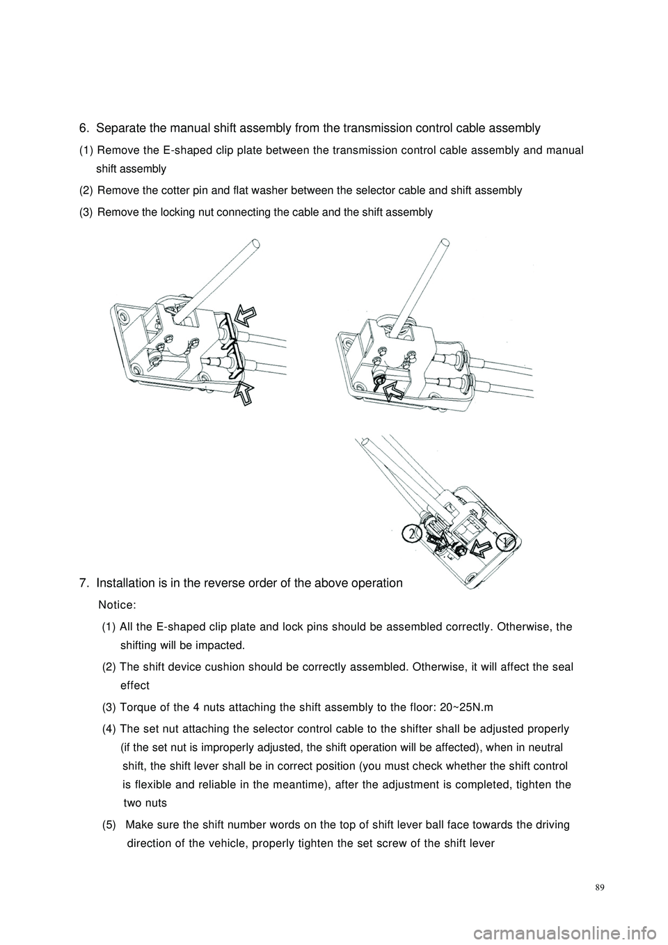
896. Separate the manual shift assembly from the transmission control cable assembly
(1) Remove the E-shaped clip plate between the transmission control cable assembly and manual
shift assembly
(2) Remove the cotter pin and flat washer between the selector cable and shift assembly
(3) Remove the locking nut connecting the cable and the shift assembly
7. Installation is in the reverse order of the above operation
Notice:
(1) All the E-shaped clip plate and lock pins should be assembled correctly. Otherwise, the
shifting will be impacted.
(2) The shift device cushion should be correctly assembled. Otherwise, it will affect the seal
effect
(3) Torque of the 4 nuts attaching the shift assembly to the floor: 20~25N.m
(4) The set nut attaching the selector control cable to the shifter shall be adjusted properly
(if the set nut is improperly adjusted, the shift operation will be affected), when in neutral
shift, the shift lever shall be in correct position (you must check whether the shift control
is flexible and reliable in the meantime), after the adjustment is completed, tighten the
two nuts
(5) Make sure the shift number words on the top of shift lever ball face towards the driving
direction of the vehicle, properly tighten the set screw of the shift lever
Page 101 of 392
94Section 3 Clutch hydraulic Control DeviceComponents
Clutch Sub-pump
Transmission Assembly
Reservoir
Cowl Baffle
Clutch And Brake Pedal Assembly
Clutch Master Cylinder
Clutch Master
Cylinder
Master Cylinder Bracket
Clamp Clamp
Connect The Pipe Assembly
Hose Union
Reservoir Hose 2Reservoir Hose 1
Clog Bolt
Rubber Washer
Union Nut
Hydraulic Hose
L Shaped Clip Plate L Shaped Clip Plate
Pivot
Page 349 of 392

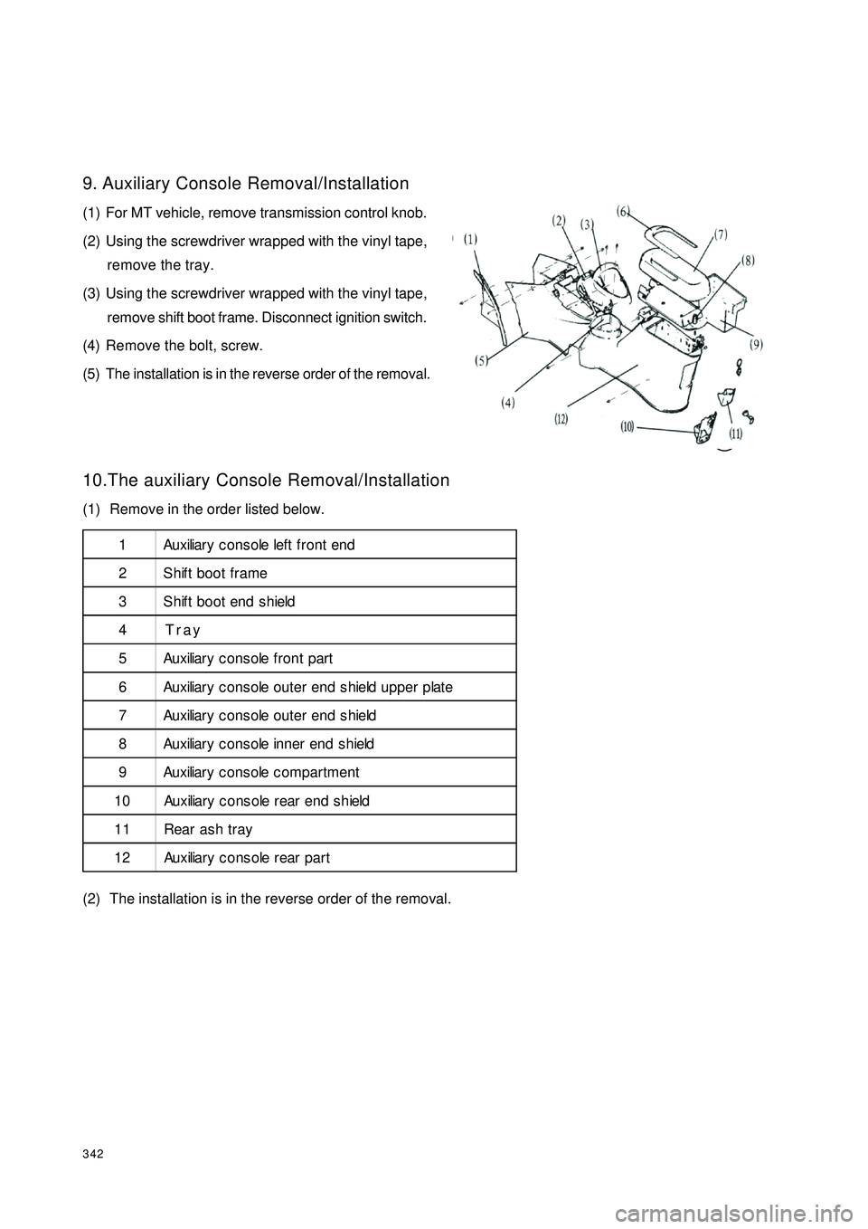
3429. Auxiliary Console Removal/Installation
(1) For MT vehicle, remove transmission control knob.
(2) Using the screwdriver wrapped with the vinyl tape,
remove the tray.
(3) Using the screwdriver wrapped with the vinyl tape,
remove shift boot frame. Disconnect ignition switch.
(4) Remove the bolt, screw.
(5) The installation is in the reverse order of the removal.
10.The auxiliary Console Removal/Installation
(1) Remove in the order listed below.
(2) The installation is in the reverse order of the removal.11
2 3
4 5 6
7
8
9
10
11 121 Au x iliar y c o n s o le lef t f r o n t e n d
2 Shift boot frame
3 Shift boot end shield
4Tray
5 Au x iliar y c o n s o le f r o n t p ar t
6 Au x iliar y c o n s o le o u t e r e n d s h ie ld u p p e r p lat e
7 Au x iliar y c o n s o le o u t e r e n d s h ie ld
8 Au x iliar y c o n s o le in n e r en d s h ield
9 Au x iliar y c o n s o le c o m p ar t m e n t
1 0 Au x iliar y c o n s o le r e ar e n d s h ie ld
11 Rear ash tray
1 2 Au x iliar y c o n s o le r e ar p a r t
Page 369 of 392

362(II) Floor AssemblyFloor assembly is the base of the main body and an important structure component to link with assemblies
and for load transfer and bearing. The vehicle running performance depends on its intensity and rigidity.
Figure 5-3 is the dismantle diagram of the floor parts.
Floor assembly is composed of front floor assembly and rear floor assembly. A protrusile tunnel runs longitu-
dinally in the center of the front floor. The tunnel and the lower floor rail can strengthen its rigidity in
longitudinal direction. The lower space of the tunnel is used to mount components such as transmission shift
pull rod, park brake drawing cable, exhaust pipes with 3-way catalytic converter. Carpet and sound insulator
mat are mounted in the inner side of the compartment. The first and the second cross member, LH/RH side
member and side rails which are on the front floor form a frame structure. It can provide great load-bearing
capacity to assure strict running requirements for body.
Figure 5-3 Decomposition Diagram of Floor Parts
1 LH/RH Front Floor Side Rail 2 Front Floor 3 Front Floor Cross Member 4 LH/RH Floor Side
Member 5 Rear Floor 1st Cross Member 6 LH/RH Rear Floor Side Rail 7 Rear Floor 2nd Cross
Member Assy. 8 Rear Floor2143456 678Front