Page 271 of 467
Brake/Transaxle Interlock System
This system prevents you from moving the gear selector
lever out of PARK and into any gear unless the brake
pedal is pressed. This system is active only while the
ignition switch is in the ON position. Always press the
brake pedal first, before moving the gear selector out of
PARK.
NOTE: If a malfunction occurs, the transaxle will not
shift out of park. Battery power is required to release the
brake/transaxle interlock system. However, there is an
override system that allows you to shift out of Park in
case of loss of power. To activate the override system:
² Firmly apply the parking brake
² Insert the ignition key and rotate it to the ON position
² Remove the cup holder liner ² Insert a key, screwdriver, or finger into the front hole
then push and hold the manual override release lever
forward.
² While holding the release lever forward, move the
gear selector lever from PARK to NEUTRAL. Release
the override
NOTE: If this occurs, even if the override is successful,
it is recommended that you visit a dealer at your earliest
possible convenience. Your dealer has diagnostic equip-
ment to determine if the problem could recur.
Automatic Transaxle Ignition Interlock System
This system prevents the key from being removed unless
the shift lever is in PARK. It also prevents shifting out of
PARK unless the key is in the ON position and the brake
pedal is applied.
NOTE: If a malfunction occurs, the system will trap the
key in the ignition cylinder to warn you that this safety STARTING AND OPERATING 269
5
Page 275 of 467

CAUTION!If the transaxle operating temperature exceeds ac-
ceptable limits, the vehicle computer will override
OVERDRIVE and ª3º DRIVE range by changing
shift points. This is done to prevent transaxle damage
due to overheating.
Reset Mode - Electronic Transaxle
The transaxle is monitored electronically for abnormal
conditions. If a condition is detected that could cause
damage, the transaxle automatically shifts into second
gear. The transaxle remains in second gear (3rd gear with
a six speed automatic) despite the forward gear selected.
Park (P), Reverse (R), and Neutral (N) will continue to
operate. This Reset feature allows the vehicle to be driven
to a dealer for service without damaging the transaxle. In the event that the problem has been momentary, the
transaxle can be reset to regain all forward gears.
1. Stop the vehicle.
2. Shift into PARK.
3. Turn the ignition OFF, and then restart the engine.
4. Shift into the desired gear range and resume driving.
NOTE: Even if the transaxle can be reset, it is recom-
mended that you visit a dealer at your earliest possible
convenience. Your dealer has diagnostic equipment to
determine if the problem could recur.
If the transaxle cannot be reset, dealer service is required. STARTING AND OPERATING 273
5
Page 332 of 467
WARNING!² Never have any smoking materials lit in or near
the vehicle when the gas cap is removed or the
tank filled.
² Never add fuel when the engine is running. This is
in violation of most state and federal fire regula-
tions and doing so will cause the malfunction
indicator light to turn on.
² A fire may result if gasoline is pumped into a
portable container that is inside of a vehicle. You
could be burned. Always place gas containers on
the ground while filling.
NOTE:
² Tighten the gas cap until you hear a ªclickingº sound.
This is an indication that the gas cap is tightened
properly. The Malfunction Indicator Light in the in-
strument cluster may turn on if the gas cap is not secured properly. Make sure that the gas cap is tight-
ened each time the vehicle is refueled.
² When the fuel nozzle ªclicksº or shuts off, the fuel
tank is full.
LOOSE FILLER CAP MESSAGE
If the vehicles diagnostic system determines that the fuel
filler cap in loose, improperly installed, or damaged, a
ªgASCAPº message will be displayed in the instrument
cluster. Tighten the gas cap until a ªclickingº sound is
heard. This is an indication that the gas cap is properly
tightened. Press the trip odometer reset button to turn off
the message. If the problem persists, the message will
appear the next time the vehicle is started. This might
indicate a damaged cap. If the problem is detected twice
in a row, the system will turn on the Malfunction
Indicator Light (MIL). Resolving the problem will turn
the MIL light off.330 STARTING AND OPERATING
Page 335 of 467
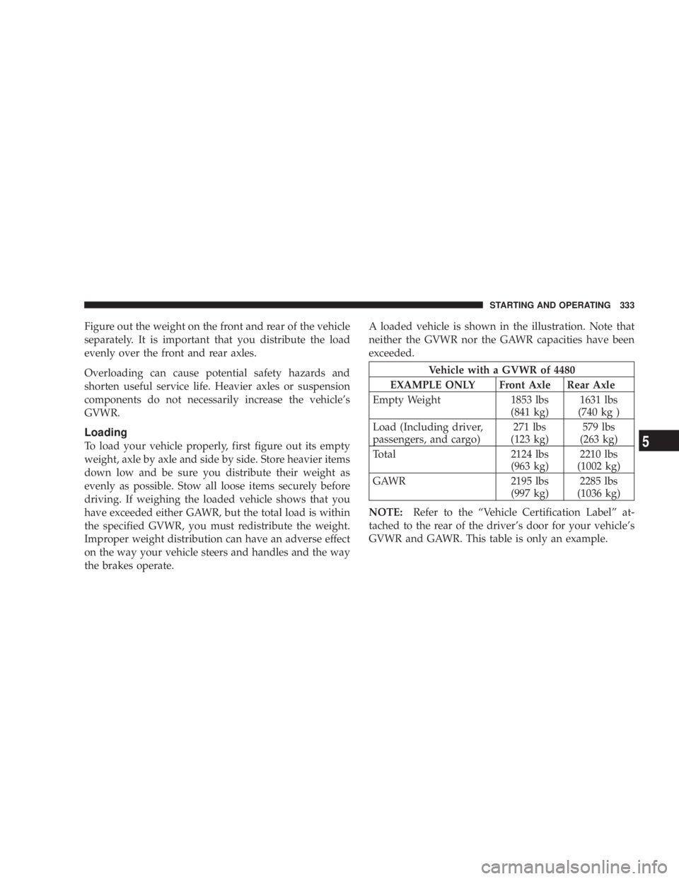
Figure out the weight on the front and rear of the vehicle
separately. It is important that you distribute the load
evenly over the front and rear axles.
Overloading can cause potential safety hazards and
shorten useful service life. Heavier axles or suspension
components do not necessarily increase the vehicle's
GVWR.
Loading
To load your vehicle properly, first figure out its empty
weight, axle by axle and side by side. Store heavier items
down low and be sure you distribute their weight as
evenly as possible. Stow all loose items securely before
driving. If weighing the loaded vehicle shows that you
have exceeded either GAWR, but the total load is within
the specified GVWR, you must redistribute the weight.
Improper weight distribution can have an adverse effect
on the way your vehicle steers and handles and the way
the brakes operate. A loaded vehicle is shown in the illustration. Note that
neither the GVWR nor the GAWR capacities have been
exceeded.
Vehicle with a GVWR of 4480
EXAMPLE ONLY Front Axle Rear Axle
Empty Weight 1853 lbs
(841 kg) 1631 lbs
(740 kg )
Load (Including driver,
passengers, and cargo) 271 lbs
(123 kg) 579 lbs
(263 kg)
Total 2124 lbs
(963 kg) 2210 lbs
(1002 kg)
GAWR 2195 lbs
(997 kg) 2285 lbs
(1036 kg)
NOTE: Refer to the ªVehicle Certification Labelº at-
tached to the rear of the driver's door for your vehicle's
GVWR and GAWR. This table is only an example. STARTING AND OPERATING 333
5
Page 342 of 467
WARNING!Improper towing can lead to an injury accident.
Follow these guidelines to make your trailer towing
as safe as possible:
Make certain that the load is secured in the trailer
and that it will not shift during travel. When traile-
ring cargo that is not fully secured, dynamic load
shifts can occur that may be difficult for the driver to
control. You could lose control of your vehicle and
have an accident.
² When hauling cargo, or towing a trailer, do not
overload your vehicle or trailer. Overloading can cause
a loss of control, poor performance, or damage to
brakes, axle, engine, transaxle, steering, suspension,
chassis structure, or tires. ² Safety chains must always be used between your
vehicle and trailer. Always connect the chains to the
frame or hook retainers of the vehicle hitch. Cross the
chains under the trailer tongue and allow enough
slack for turning corners.
² Vehicles with trailers should not be parked on a grade.
When parking, apply the parking brake on the tow
vehicle. Put the tow vehicle automatic transaxle in
PARK. Always, block or 9 chock 9 the trailer wheels.
² GCWR must not be exceeded.
² Total weight must be distributed between the tow
vehicle and the trailer such that the following four
ratings are not exceeded:
1. GVWR
2. GTW
3. GAWR340 STARTING AND OPERATING
Page 358 of 467
3. There are two front jacking locations and two rear
jacking locations on each side of the body as shown.
CAUTION!Do not attempt to raise the vehicle by jacking on
locations other than those indicated in step 3.
4. Turn the jack screw to the left until the jack can be
placed under the jacking location. Once the jack is
positioned, turn the jack screw to the right until the jack
head is properly engaged with the lift area closest to the
wheel to be changed. Do not raise the vehicle until you
are sure the jack is securely engaged. WARNING!Raising the vehicle higher than necessary can make
the vehicle less stable. It could slip off the jack and
hurt someone near it. Raise the vehicle only enough
to remove the tire.
5. Raise the vehicle by turning the jack screw to the right,
using the swivel wrench. Raise the vehicle only until the
tire just clears the surface and enough clearance is
obtained to install the spare tire. Minimum tire lift
provides maximum stability.
6. Remove the wheel nuts, and pull the wheel and wheel
covers (where applicable) off the hub. Install the spare
wheel and wheel nuts with the cone shaped end of the
nuts toward the wheel. Lightly tighten the nuts. To avoid
the risk of forcing the vehicle off the jack, do not tighten
the nuts fully until the vehicle has been lowered.356 WHAT TO DO IN EMERGENCIES
Page 359 of 467
WARNING!To avoid possible personal injury, handle the wheel
covers with care to avoid contact with any sharp
edges.
7. Lower the vehicle by turning the jack screw to the left.
8. Finish tightening the nuts. Push down on the wrench
while tightening the wheel nuts. Alternate nuts, until
each nut has been tightened twice. Correct wheel nut
torque is 100 ft. lbs (135 N´m). If you doubt that you have
tightened the nuts correctly, have them checked with a
torque wrench by your dealer or at a service station.
9. Remove the wheel blocks and lower the jack until it is
free. Reassemble the lug wrench to the jack assembly and
stow it in the spare tire area. Secure the assembly using
the means provided. WARNING!A loose tire or jack thrown forward in a collision or
hard stop could endanger the occupants of the ve-
hicle. Always stow the jack parts and the spare tire in
the places provided.
10. Place the deflated (flat) tire in the cargo area and have
the tire repaired or replaced as soon as possible.
WARNING!A loose tire thrown forward in a collision or hard
stop could injure the occupants in the vehicle. Have
the deflated (flat) tire repaired or replaced
immediately. WHAT TO DO IN EMERGENCIES 357
6
Page 386 of 467
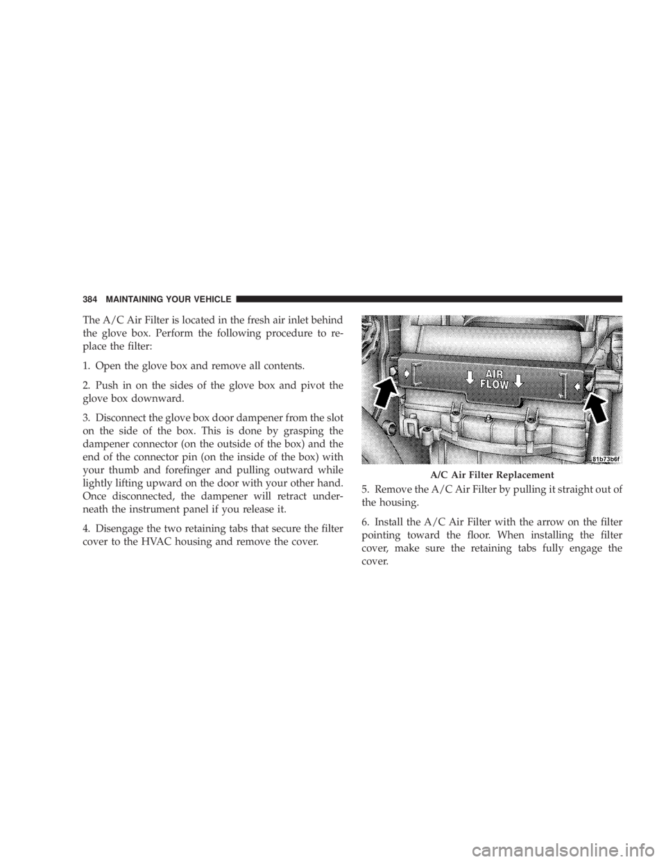
The A/C Air Filter is located in the fresh air inlet behind
the glove box. Perform the following procedure to re-
place the filter:
1. Open the glove box and remove all contents.
2. Push in on the sides of the glove box and pivot the
glove box downward.
3. Disconnect the glove box door dampener from the slot
on the side of the box. This is done by grasping the
dampener connector (on the outside of the box) and the
end of the connector pin (on the inside of the box) with
your thumb and forefinger and pulling outward while
lightly lifting upward on the door with your other hand.
Once disconnected, the dampener will retract under-
neath the instrument panel if you release it.
4. Disengage the two retaining tabs that secure the filter
cover to the HVAC housing and remove the cover. 5. Remove the A/C Air Filter by pulling it straight out of
the housing.
6. Install the A/C Air Filter with the arrow on the filter
pointing toward the floor. When installing the filter
cover, make sure the retaining tabs fully engage the
cover. A/C Air Filter Replacement384 MAINTAINING YOUR VEHICLE