2008 AUDI TT ROADSTER change time
[x] Cancel search: change timePage 22 of 316

Instruments and warning/indicator lights
Brake system BRAKE (USA)/ (CD) (Canada)
This warning/i ndi cat or light illumina tes whe n th e brake
fluid level i s to o low or w hen t here is a malfuncti on in the
ABS , or w hen the pa rkin g br ake is set.
The ligh t illumin ates when the igniti on is turned on . It goes out aft er
th e engine has been started and the parking brake is fu lly r eleased.
Th is i ndicates that t he bra ke w arning ligh t is f uncti oning properly .
If the brake warning light does not light up when the engine is
cranking or the parking brake is applied , there may be a malfunction
in the electrical system. In thi s case , contact your Audi dealer.
When the light com es on, an acoustic warn ing signa l will sound .
Parking brake set
The BRAKE warning/indicator light illuminates when the parking
br ak e i s set :::::,& .
& WARNING
• USA model s.~ If both , the BRAKE warning light and the ~
warning light come on at the same time , the rear wheels could
lock up first under hard braking . Lo ck-up of the rear wheel brakes
can cause loss of vehicle control and an accident . Have your
vehicle repaired immediately by your authorized Audi dealer or a qualified workshop . Drive slowly and avoid sudden, hard brake
application.
• Canada models : If both , the b rake warning light
((j)) and the ABS
warning light come on at the same time , the rear wheels could
lock up first under hard brak ing . Lock -up of the rear wheel brakes
c an cause loss of vehicle control and an accident. Have your
vehi cle repaired immediately by your authorized Audi dealer or a
qualified workshop . Drive slowly and avoid sudden , hard brake
application
• If the brake warning /indicator light does not go out after a few
seconds and the parking brake released , or lights up while you are
& WARNING (continued)
driving , the fluid level in the brake fluid reservoir is too low . If you
believe that it is safe to do so, proceed immediately at low speed
to the nearest authorized Audi dealer or qualified workshop and
have the brake system inspected.
• Please be very careful and always keep in mind that after
several brake applications, you will need greater pressure on the
brake pedal to stop your vehicle . Consequently , you must allow for
increased braking distances. Trying to brake as qui ckly as usual
c ould lead to an ac cident . •
Anti-lock brake system 8 (USA)/
~ (Canada)
This warni ng /ind icato r lig ht moni tors the AB S and the
electronic differenti al lock (EDL).
The light will come on for a few seconds when the ignition is
switched on. The light wil l go out after an automatic check sequence
is completed.
There is a malfunction in the ABS when :
• The warnin g/i ndica to r l ight do es no t illumin ate when you swi tch
on the ignition .
• The warn ing/i ndi cator lig ht does not go ou t after a few seconds .
• T he warning/indicator l ight il luminates whi le driving.
The brake system will still respond even without the assistance of
the ABS system. See your authorized Audi dealer as soon as possible to restore full braking performance . For more in for mati on
regarding t he ABS=> page
189.
The ABS warning l ight and the brake warning light come on
together . The ABS will not work and you will notice a change in
braking response and performance .
Page 27 of 316

If, however, the Malfunction Indicator Lamp (MIU comes on,
always drive to your nearest authorized Audi dealer or qualified
workshop and have the vehicle checked.
For more information =>
page 216, "Refuelling".•
Service interval display
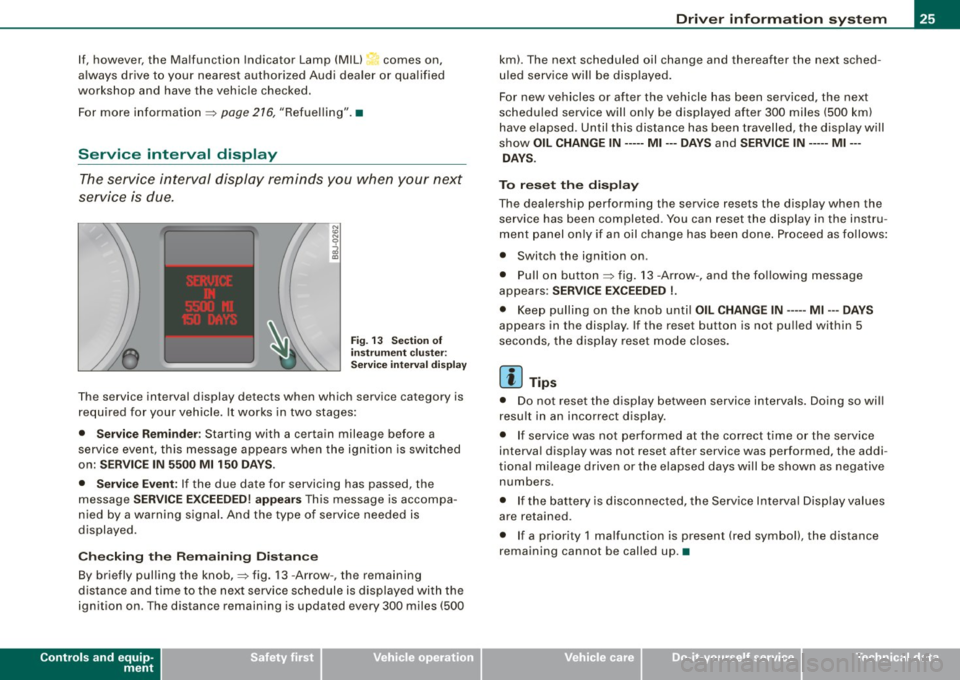
The service interval display reminds you when your next
service is due.
Fig. 13 Section of
instrument cluster:
Service interval display
The service interval display detects when which service category is
required for your vehicle. It works in two stages:
• Service Reminder : Starting with a certain mileage before a
service event, this message appears when the ignition is switched
on:
SERVICE IN 5500 Ml 150 DAYS.
• Service Event:
If the due date for servicing has passed, the
message
SERVICE EXCEEDED! appears This message is accompa
nied by a warning signal. And the type of service needed is
displayed.
Checking the Remaining Distance
By briefly pulling the knob,=> fig. 13 -Arrow -, the remaining
distance and time to the next service schedule is displayed with the
ignition on . The distance remaining is updated every 300 miles (500
Controls and equip
ment
Driver information system
km). The next scheduled oil change and thereafter the next sched
uled service will be displayed.
For new vehicles or after the vehicle has been serviced, the next
scheduled service will only be displayed after 300 miles (500 km)
have elapsed. Until this distance has been travelled, the display will
show
OIL CHANGE IN----- Ml ---DAYS and SERVICE IN----- Ml --
DAYS.
To reset the display
The dealership performing the service resets the display when the service has been completed . You can reset the display in the instru
ment panel only if an oil change has been done. Proceed as follows:
• Switch the ignition on .
• Pull on button=> fig.
13 -Arrow-, and the following message
appears:
SERVICE EXCEEDED !.
• Keep pulling on the knob until OIL CHANGE IN ---- -Ml ---DAYS
appears in the display. If the reset button is not pulled within 5
seconds, the display reset mode closes.
[ i] Tips
• Do not reset the display between service intervals. Doing so will
result in an incorrect display.
• If service was not performed at the correct time or the service
interval display was not reset after service was performed, the addi
tional mileage driven or the elapsed days will be shown as negative
numbers.
• If the battery is disconnected, the Service Interval Display values
are retained.
• If a priority 1 malfunction is present (red symbol), the distance
remaining cannot be called up. •
I • •
Page 39 of 316

When this symbol ' illuminates, it means that Adaptive Light is
defective. Go to a qualified workshop to have the headlights or the
control unit for the Adaptive Light repaired. •
Applies to vehic les: w it h tir e p ressure monitor in g system
Tire pressure monitoring system J
Tire pressure that is too low must be corrected as soon as
possible .
If the 'symbol flashes for about one minute after the igni
tion is switched on and then remains on, there is a malfunc
tion in the system. Consult the nearest authorized Audi
dealer as soon as possible.
Additional information about the tire pressure monitoring system
can be found: => page 41. •
Speed warning system
Overview
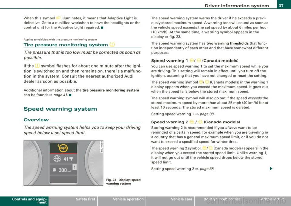
The speed warning system helps you to keep your driving
speed below a set speed limit.
Controls and equip
ment
Fig . 23 Display: speed
warning system
Driver inform ation system
The speed warning system warns the driver if he exceeds a previ
ously stored maximum speed. A warning tone wi ll sound as soon as
the vehicle speed exceeds the set speed by about 6 miles per hour (10 km/h). At the same time, a warning symbol appears in the
display=> fig. 23.
The speed warning system has
two warning thresholds that func
tion independently of each other and that have somewhat different
purposes :
Speed warning 1 )f ..._ (Canada models)
You can use speed warning 1 to set the maximum speed while you
are driving . This setting will remain in effect until you turn off the
ignition, assuming that you have not changed or reset the setting.
The speed warning symbol
J I ,.... (Canada models) in the warning 1
display appears when you exceed the maximum speed . It goes out
when the speed falls below the stored maximum speed.
The speed warning symbol will also go out if the speed
exceeds the
stored maximum speed by more than about 25 mph (40 km/h) for at
least 10 seconds. The stored maximum speed is deleted .
Setting speed warning 1 =>
page 38.
Speed warning 2 ...,,, /
e!. (Canada models)
Storing warning 2 is recommended if you always want to be
reminded of a certain speed, for example when you are traveling in
a country that has a general maximum speed limit, or if you do not
want to exceed a specified speed for winter tires.
The speed warning 2 symbol, / ) (Canada models) appears in the
display when you exceed the stored speed limit. Unlike warning 1,
it wi ll not go out until the vehicle speed drops below the stored
speed limit .
Setting speed warning 2 =>
page 38 .
I • •
Page 42 of 316

Driver inf ormation sy ste m
To ta l-tr ip mem ory ( Trip compu te r 2)
Unlike the single -trip memory, the total -tr ip memory is not reset
automatically . This permits you to evaluate your driving data for the
entire period between manua l resets.
Fu el r an ge
The estimated cruising range in miles (km) appears in the display.
This tells you how far your vehicle will be able to travel on the
current tank of fuel and with the same driving sty le . The display
changes in increments of 6 miles (10 km).
The cruising range is calculated based on the fuel consumption for
t he last 18 miles (30 km). If you drive conservatively, the cruising
range will increase .
Average fuel m ile ag e
The average fuel economy in MPG (1/100 km) since you last cleared
the memory appears in this display. You can use this display to
adjust your driving technique to achieve a desired mileage.
C ur rent fuel mil eage
The instantaneous fuel consumption in mi les per gallon (1/100 km)
is shown in th is d isplay. You can use this display to adjust your
driving technique to achieve a desired mileage.
Fue l consumption is recalcu la ted at intervals of 33 yards (30
meters). When the vehicle is stationary, the most recent fuel
consumption is d isplayed .
Average speed
The average speed in mph (km/h) s ince the last time the display was
reset appears in the display .
Elap se d time
The length of time that you have been driving since you last reset
the memory appears in this display.
Di stance
The elapsed distance since the last time the memory was cleared
appears in the display. The maximum distance that can be recorded
is 9,999 .9 miles (9,999 .9 kilometers).
[ i ] Tips
• Fuel consumptions (average and current), range and speed are
displayed in metric units on Canadian models.
• All stored values will be lost if the vehicle battery is
disconnected .•
Operation
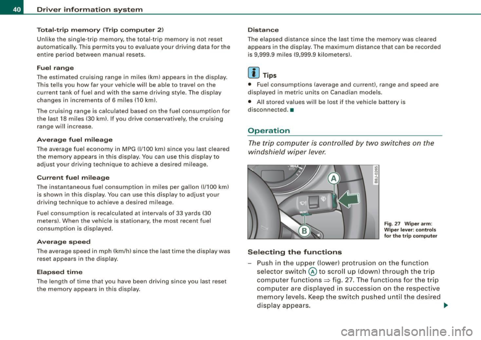
The trip computer is controlled by two switches on the
windshield wiper lever.
S ele cting th e fun ctions
Fig. 27 Wiper ar m:
W iper l ever: co ntrols
fo r th e tr ip com pute r
P u sh in the upper (lower) pro trusion o n the function
se lector switch @to scroll up (dow n) through the trip
computer functions~ fig. 27. The functions for the trip
comp uter are displayed in succession on the respect ive
memory leve ls. Keep the switc h pus hed until the desired
display appears . .-,,
Page 46 of 316

Driver inf ormation sy ste m
Storing tire pressures
Correct storage of specified pressure is the basic require
ment for reliable tire pressure monitoring.
F ig . 29 S ET -butt on:
T ire pressure mon i
t or ing syste m
In order for the tire pressure monitori ng system to operate
appropr iately, you have to re-save the specified p ressures
whenever you adjust tire pressures, for example when the load co nd ition of your vehicle changes. Proceed as fo llows:
Corr ecting tir e pr es sure
Check the pressure in the t ires.
- Adjust air pressure as needed to comply w ith the infor
mat ion on the label located on the driver's side B -pillar
(visible when the door is open) .
Saving tire pressures
-Turn on the igniti on.
- Press the button :::> fig. 29 for app rox imately 5 seconds.
You will hear a beep and the symbol in the instrument
cluster flashes three t imes .
All pressure warning indicators in the d isplay will be canceled. Following each intentional change in specified pressures, ti
re pres
sures must be resaved.
After the pressures are saved, the tire pressure monito ring system
measures the current tire pressures and saves them as the new
spec ified pressures .
[ i ] Tip s
• The tire pressure is shown on the tire pressure labe l. The tire
pressur e lab el is located on the driv er's sid e B-pillar (visible when
the door is open). The tire pressure label l ists the recommended
cold tir e inflation pr essur es for the vehic le at its maximum capacity
weigh t and the tires that were on your vehicle at the time it was
manufactured . For recommended tire pressures for norma l load
conditions, please see chapter~
page 242.
• The tire pressure monitoring syst em he lps the driver to keep an
eye on tire pressures. But the driver still has the responsibility for
maintaining the cor rect tire pressure .•
Wheel change
If a wh eel is ch anged , the wheels tha t were exchan ged
have to be re -programmed.
- Tu rn on the ignition.
- Press the button :::> fig. 29 for approximately 5 seconds .
You will hear a beep and the symbol in the button flashes
three times.
Programming is necessary :
• after the t ires have been rotated on the vehicle, or the spare tire
is used,
• if tires with new wheel sensors are used .
All pressure warning indicators in the disp lay wil l be canceled . The
system malfunction error message will not disapp ear until the .,_
Page 47 of 316

vehicle is underway. With pressing the button=> fig . 29, the re
programming of the new sensors and storing of actual pressures
starts . This learn ing phase can take up to 10 minutes driving time.
During the learning process the tire pressure monitoring system is
not avai lable. •
Malfunctions T =»'\,AC.:
A malfunction can have various causes.
Fig. 30 Display:
System malfunction
If the t warning light in the instrument cluster flashes for approxi
mately one minute and then remains continuously illuminated and
additionally the
r fin'-=> fig. 30 symbo l appears in the display, the
tire pressure monitoring system is not available. This can have
various causes .
• If the message appears at the end of the learning process, the
system cannot recognize the wheels installed on the vehicle. This
can be because one or more wheels without a whee l sensor were
installed.
• A wheel sensor or other component may have failed .
• During initia lization the system has detected more than 4 wheels
on the vehicle, for example whi le driving next to another car with a
tire pressure monitoring system.
Controls and equip
ment
Driver inform ation system
• A wheel change was made but the button => page 44, fig. 29 was
not pressed .
• Audi replacement parts were not used.
• If snow chains are being used, system function can be compro
mised due to the shielding properties of the chains.
• The tire pressure monitoring system may not be available
because of a radio malfunction.
• Transmitters with the same frequency, such as radio head
phones in the vehic le or radio equipment, can cause a temporary
disruption of the system through excessive e lectromagnetic fields.
• Eliminate the interference if possible/if you can and then
proceed as follows: Turn off the engine for 20 minutes . Then drive
another 10 min. If the warning light comes on again, you should
contact your authorized Audi dealer immediately to have the
problem corrected.
• Do not use commercially available tire sealants. Otherwise, the
e lectrica l components of the tire pressure monitoring system will
no longer work properly and the sensor for the tire pressure moni
toring system will have to be replaced by a qualified workshop. •
Certification
This device complies with part 15 of the FCC rules and RSS-210.
Operation is subject to the following conditions:
• this device may not cause harmful interference, and
• this device must accept interference received, includ ing interfer
ence that may cause undesired operation.
The receiver 5WK49069 uses the same schematic, assembly, layout
and PCB as 5WK49097 . 5WK49097 is a multi channe l receiver and
5WK49069 is a single channel receiver. They only differ in: SAW -
Filter V1_4 was changed from A2C00038979 to V1_2 A2C00032378,
Inductor L5_3 and L6_233nH were changed to L5_2 and L6_2 47nH.
BAND PASS FILTER V3_2 was changed from A2C00038762 to V3_3
A2C00036085. V 10: ATIC75 C1, A2C000029505 was changed to V10: .,,,
I • •
Page 73 of 316

• Do not attach stickers to the windshie ld in front of the sensors as
this can disable the automatic head -and tail light control and the
automatic glare -dimming of the rearview mirror(s) .
• Always o bserve the spec ific loca l regu la tions f or your area when
to use your lights .
• I n the event of a light sensor mal function, the d river informa tion
display will show the symbol . If a light sensor malfunct ion is indi
ca te d , you must use the ligh t switch to turn the low beams on and
off .•
Daytime running lights (DRL ) (USA models )
The daytime running ligh ts are tu rne d o n auto maticall y
w hen t he ignit ion is s witche d on.
Activating functions
Fig . 63 Sw itch for
daytime running lights
- Move the right thumbwhee l@ "D RL" ~ fig. 63 to posi
t io n
(D .
Deactivating functions
- Mov e th e rig ht thum bwh eel "DR L" to posi tion @ .
Con tro ls and eq uip
ment
Clear vision
T he daytime running lights can be turned on or off using this func
t ion. If the f unc tion is ac tive, the dayti me r unning ligh ts are turn ed
on automatically when the ignition is switched on .
The daytime running lights are activated
only when the light switch
=> fig . 63 @ is at the O or AUTO* position .
& WARNING
Never use daytime running lights to see where you are going . They
are not bright enough and will not let you see far enough ahead for
s afety , e speci ally at dusk o r when it is dark . Be aware of changes
in outside light conditions when you are driving and respond by
sw itching on your low beams
io.
0 Note
Alway s be aware of change s in outside light conditions while you
a re dr iving. Respond in time to fading daylight by turning the light
s witch to position
io (or "AUTO" if your car is equipped with this
feature)
to turn on your headlights .•
Daytime running lights (Canada models only)
W hen yo u turn on the ig nit io n the daytime running lights
will come on automatically.
The daytime running lights are activated only when the light switch
@ =>fig. 63 is e ither at the
O o r the :oo: position . Whe n the ignition
is switched on, there is a difference between vehicles with bi -xenon
lig hts and ha logen lamps :
• On vehicles with bi -xenon lights only the daytime running lamps
in the headlights will c ome on.
• On vehicles with halogen lights the front fog lights, side marker
lights and tail ligh ts come on automa tica lly
~
Vehicle care I I irechnical data
Page 74 of 316

Clear vision
& WARNING
Never use daytime running lights to see where you are going. They
are not bright enough and will not let you see far enough ahead for
safety , especially at dusk or when it is dark . Be aware of changes
in outside light conditions when you are driving and respond by
switching on your low beams
fD.
0 Note
• With the light switch at the O or ;:oo: position , only your front fog
lights remain turned on when it turns dark outside . Even though
your instruments appear well lit, the road ahead of you is not. The
light pattern provided by fog lights alone is not suffic ient for safe
driving in poor light or darknes s. Therefore:
• Always be aware of changes in outside light conditions while
you are driving. Respond in time to fading daylight by turning the
light swit ch to position @:D (or "AUTO" if your car is equipped with
th is feature) to turn on your headlights.
[ i ] Tips
The day tim e run ning lig ht s fu nct io n c annot b e tur ned off. •
Applies to vehicles: with Adap tive ligh t
Adaptive light
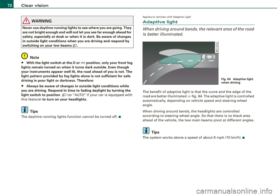
W he n dri vin g around be nds , the r eleva nt area of the road
is b ette r illumin ated.
Fig. 64 Adapt ive light
when driving
T he bene fit of ada ptive lig ht is th at t he cu rve a nd the e dge of the
road are b etter illuminated=> fig. 64 . The adaptive light is controlled
a uto ma tically, de pendin g on ve hicle speed a nd s tee rin g w heel
angle.
When d riving around bends , the headlights are controlled
according t o steeri ng w heel angle. S o that ther e is no blac k ar ea
ahead of the veh icle, the two main beams pivot at different angles.
[ i ] Tips
T he system wor ks above a speed of about 6 mp h (10 km/ h). •