2008 AUDI TT ROADSTER service
[x] Cancel search: servicePage 250 of 316

___ T_ i_ r_e _s_ a_ n_ d_ w_ h_ e_ e _ ls _________________________________________________ _
Check the tire sidewall (=> page 249,
fig. 164) to determine the designated
load rating for a specific ti re. •
Tire service life
The service life of tires depends on a lot of different things
including proper installation and balancing, correct tire
pressure and driving style.
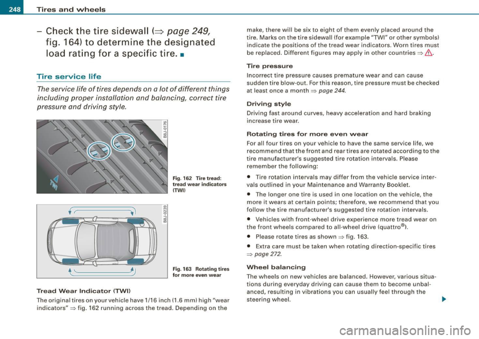
Tread Wear Indicator (TWll
"' M
J
Fig. 162 Tir e tread:
tre ad we ar indi cator s
(TWll
Fig . 163 Rotating tires
for more even wear
The original tires on your veh icle have 1/16 inch (1.6 mm) high "wear
indicators" => fig . 162 running across the tread. Depending on the make, there will be six to eight of them evenly p
laced around the
t ire. Marks on the tire sidewall (for example "TWI" or other symbols)
indicate the positions of the tread wear indicators. Worn tires must
be rep laced. Different figures may apply in other countries =>& .
Tire p ressure
Incorrect tire pressure causes premature wear and can cause
sudden tire blow-out . Forth is reason, tire pressure must be checked
at least once a month
==> page 244.
Driving style
Driving fast around curves, heavy acceleration and hard braking
increase tire wear.
Rotating tires for more even wear
For all four tires on your vehicle to have the same service life, we
recommend that the front and rear tires are rotated according to the
tire manufacturer 's suggested tire rotation intervals. Please
remember the following:
• Tire rotation interva ls may differ from the vehicle service inter
vals outlined in your Maintenance and Warranty Booklet .
• The longer one tire is used in one location on the vehicle, the
more it wears at certain points; therefore, we recommend that you
follow the tire manufacturer's suggested tire rotation intervals.
• Vehicles with front-wheel drive experience more tread wear on
the front wheels compared to a ll-wheel drive (quattro®l .
• Please rotate tires as shown ;;:;:, fig. 163.
• Extra care must be taken when rotating direction -specific tires
==> page 272.
Wheel balancing
The wheels on new vehicles are balanced. However, various situa
tions during everyday driving can cause them to become unbal
anced, resulting in vibrations you can usual ly feel through the
steering wheel. ...
Page 255 of 316

Tires a nd wh eels -
----------------
•
0 Note
• For technical reasons, it is not genera lly possible to use the
whee l rims from other vehic les. This can hold true for wheels of the
same vehic le type.
• If the spare tire is different from the tires that you have mounted
on your vehicle (for example winter tires or wide p rofile t ires), then
use the spare tire for a short period of time only and drive with extra
care. Rep lace the flat tire with the tire matching the others on your
vehicle as soon as possible.
• If you should put different wheels and tires on your vehic le (e.g.
winter wheels and tires), you must be certain that the wheels and
tires are compat ib le w ith the tire pressure monitoring system.
Otherwise the system will register a malfunction and a fault
message will be displayed . For more informatio n, contact your Aud i
dea ler.
0 Note
• When insta lling new tires, be carefu l not to damage the va lves or
t ire p ressure moni toring syste m sensors .
• Never drive without the va lve stem cap. The va lves could get
damaged.
• I f the sensors must be replaced, then the valve must also be
replaced at t he same t ime.
Uniform tire quality grading
• Tread wear
• Traction AA A B C
• Temperature A B C Qua
lity grades can be found where applicable on the tire side wall
b etween tread shoulder a nd maximum section width =>
page 249,
fig. 164.
For example : Tread wear 200, Traction AA , Temperature A.
All passenger car tires must conform to Federa l Safety Require
ments in addit ion to these grades.
T read wear
The tread wear grade is a comparative rating based on the wear rate
o f t he tire when tes ted under contro lled condit ions on a specified
government test course.
F o r example, a tire g raded 150 would wear one and one half (1 1 /2)
times as well on the government course as a tire graded 100.
The relative performance of tires depends upon the actual condi
tions o f the ir use, however, and may depart sign ificantly from the
norm due to variations in driving habits, service practices and differ
ences in road characterist ics and c limate .
Traction
The traction grades, from highest to lowest, are AA, A, Band C.
Those grades represent the tire 's ability to stop on wet pavement as
measured under contro lled cond itions on specified government
test surfaces of asphalt and concrete. A tire marked C may have
poor t raction performance =>& .
Temperature
The temperature grades are A (the highest), B, and C, represent ing
the tire 's resistance to the generation of heat and its ability to dissi
pat e heat when tested u nder con tro lled co nditions on a specified
indoor laboratory test wheel.
Sustained high temperature can cause the material of t he ti re to
degenerate and reduce tire life, and excessive temperature can lead
to sudden tire failure=:>& .
The grade C corresp onds to a level of performance which all
passenger car tires must meet under the Federa l Motor Vehicle
Vehicle care I t •
Page 265 of 316

_____________________________________________ W_ h_ a_t _d.....;. o_ l _d _o :....:.. n:..o:.. w.:....... ?:....:..--Jffllll
& WARNING
• Using a bumper jac k to raise the vehicle will damage the
bumper system . The jack may slip , causing injury .
• Never support your veh icle on cinder blocks , bri cks or other
obje cts. The se may not be able to support the load and could
c ause injury when they fail.
• Never start or run the engine while the vehicle is supported by
the jack .
• If you mu st work under the vehicle, always use safety stands
specifically des igned for this purpose .
• Never use the he xagonal socket in the handle of the screw
driver to loo sen or tighten the wheel bolts . •
Tire repair
App lies to vehicles: with Tire Mob ility System
General and safety pointers
Tire repair is in tended only for te m porary, shor t- te rm use.
®
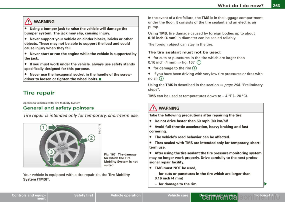
Fig . 16 7 Tire damage
for which the Tire Mobility Sy stem is not
suited
Your vehicle is equipped with a tire repai r kit, the Tire Mobil ity
System (TMS) *. I
n the event of a tire fai lure, the TMS is in the luggage compartment
u nde r th e floo r. It cons ists of the tir e sealan t and an el ectric a ir
pump .
U sing TMS, tire damage caused by foreign bodies up to about
0 .16 inch (4 mm ) in diam eter can be seale d relia bly.
T he foreign object can stay in the tire .
The tire sealant must not be used:
• for cuts or punctures in the tire which are large r than
0.16 inch (4 mm)~ fig . 167
G)
• for damage to the rim 0
• if you have been driving with very low tire pressures or tires w ith
n o air G)
Using the TMS is described in the section~ page
264, "Preliminary
steps" .
TMS can be used a t te m peratures down to -4 °F ( -20 °C).
& WARNING
Take the following precautions after repairing the tire :
• Do not drive faster than 50 mph (80 km /hi!
• Avoid full -throttle acceleration , heavy braking and fast
cornering .
• The vehicle's road behavior can be affe cted .
• Tires sealed with TMS are intended only for temporary , short
term use .
• After using the tire sealant the tire pressure monitoring system
m ay no longer work properly . Drive carefully to the next profes
s ional repair facility.
• TMS must NOT be used ,
- for cuts or punctures in the tire whi ch are larger than
0 .16 inch (4 mm )
- for damage to the rim
Vehicle care Do-it-yourself service irechnical data
Page 267 of 316

_______________________________________________ W_ h_ a _ t_d_ o_ l _d _o_ n_ o_ w_ ? _ __.1111
- Remove the "max. 50 mph" (80 km/h) sticker from the
sealant bottle and affix it to the instrument cluster in the
driver's view.
& WARNING
• Turn the hazard flashers on and set up the warning triangle if
you have a flat tire in moving traffic . In this way you protect your
self and other road users.
• Make sure that all passengers are in a safe place, out of the
danger zone (for example, behind a guard rail).
0 Note
Particular care is necessary if you are making a tire repair on a steep
incline.
[ i] Tips
Obey all laws. •
Applies to vehicles: with T ire Mobil ity System
Making a tire repair
Tire repair consists of the following sections.
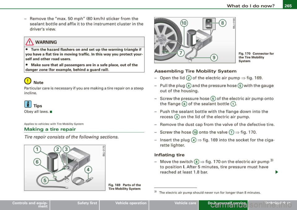
Fig. 169 Parts of the
Tire Mobility System Fig
. 170 Connector for
the Tire Mobility System
Assembling Tire Mobility System
- Open the lid 0 of the electric air pump~ fig. 169.
- Pull the plug© and the pressure hose G)with the gauge
out of the housing.
- Screw the pressure hose© of the electric air pump onto
the flange © of the sealant bottle
G).
- Push the sealant bottle with the flange down into the
recess
G) on the lid of the electric air pump.
- Remove the dust cap from the valve of the defective tire.
- Screw the hose @) onto the valve
G) ~ fig. 170.
- Insert the plug©~ fig. 169 into the socket for the ciga-
rette lighter.
Inflating tire
- Move the switch®~ fig. 170 on the electric air pump 31
to position I. After 5 minutes, tire pressure must have
reached at least 1.8 bar.
~
3> The e lectric air pump should never run for longer than 8 minutes.
Vehicle care Do-it-yourself service irechnical data
Page 269 of 316

_____________________________________________ W_ h_ a_t _d_ o_l _ d_o _ n_o_ w_ ? _ __._
- If tire pressure is less than 1.3 bar, the tire is too severely
damaged. Do not continue to drive. Seek professional
assistance.
& WARNING
If tire pressure is less than 1.3 bar after driving for 10 minutes, the
tire is too severely damaged. Do not continue to drive. Seek profes
sional assistance.
[ i] Tips
After a tire repair, have the sealant bottle replaced at a dealership.
This restores full functionality to the Tire Mobility System. •
What should I be aware of when
changing a tire?
General information
The following sections will provide you with important information
on how to change a tire using the vehicle tool kit .
However , we recommend that you have a qualified service center
change the tire and perform all work associated with changing it.•
Ap plies 10 vehicles: with decora tive wheel covers
Decorative wheel covers
The decorative wheel covers must be removed first to
access the wheel bolts.
Removing
Fig. 171 Wheel
change : removing the
wheel cover
- Insert the hook provided with the on board tool kit into
the hole on the center hub piece.
- Pull off the
decorative wheel cover=> fig. 171. •
Vehicle care Do-it-yourself service Technical data
Page 271 of 316

_______________________________________________ W_ h_ a _ t_d_ o_ l _d _o_ n_ o_ w_ ? _ __.ffllll
& WARNING
• Using force without control to speed the wheel change up can
cause the vehicle to slip off the jack and cause serious personal
injuries.
• Do not loosen the wheel bolts more than one turn before you
raise the vehicle with the jack . - Risk of injury!
[ i] Tips
• Never try and use the hexagonal socket in the handle of the
screwdriver to loosen or tighten the wheel bolts.
• If a wheel bolt sits very tight, you may find it easier to loosen by
carefully pushing down on the end of the wheel bolt wrench with
one foot only . As you do, hold on to the car to keep yourself stable
and take care not to slip. •
Rais ing the vehicle
The vehicle must be lifted with the jack first before the
wheel can be removed.
-
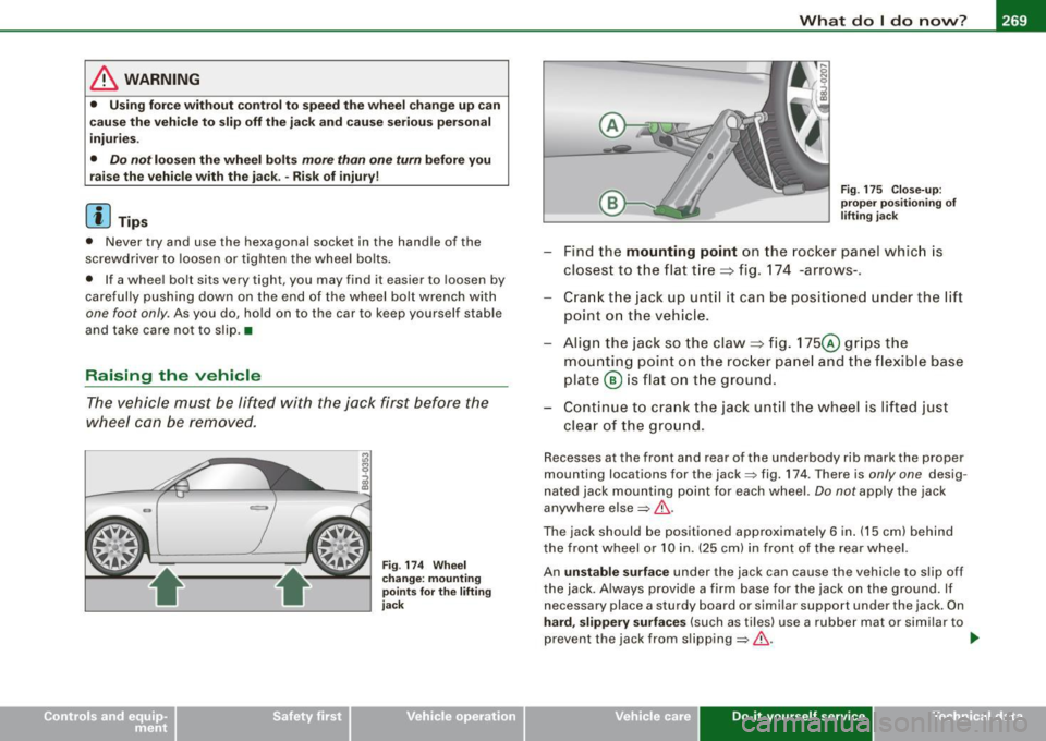
Fig. 174 Wheel
change: mounting
points for the lifting
jack Fig
. 175 Close-up:
proper positioning of
lifting jack
-Find the mounting point on the rocker panel which is
closest to the flat tire ~ fig. 174 -arrows-.
- Crank the jack up until it can be positioned under the lift
point on the vehicle.
- Align the jack so the claw~ fig. 175@ grips the
mounting point on the rocker panel and the flexible base
plate @ is flat on the ground.
- Continue to crank the jack until the wheel is lifted just
clear of the ground.
Recesses at the front and rear of the underbody rib mark the proper
mounting locations for the jack=> fig. 174 . There is
only one desig
nated jack mounting point for each wheel.
Do not apply the jack
anywhere else=>&.
The jack should be positioned approximately 6 in. (15 cm) behind
the front wheel or 10 in. (25 cm) in front of the rear wheel.
An
unstable surface under the jack can cause the vehicle to slip off
the jack. Always provide a firm base for the jack on the ground. If
necessary place a sturdy board or similar support under the jack. On
hard, slippery surfaces (such as tiles) use a rubber mat or similar to
prevent the jack from slipping=> &. .,
Vehicle care Do-it-yourself service irechnical data
Page 273 of 316

What do I do now? -
----------------
•
-Screw the threaded end of the alignment pin from the
tool kit hand-tight into the now vacant bolt hole
=:> page 270, fig. 177.
- Then completely unscrew the other wheel bolts as
described above.
- Take off the wheel leaving the alignment pin in the bolt
hole.
Putting on the wheel
- Lift the spare wheel and carefully slide it over the align
ment pin to guide it in place.
- Use the hexagonal socket in the screwdriver handle to
screw in and tighten all wheel bolts slightly.
- Unscrew the alignment pin and insert and tighten the
remaining wheel bolt slightly like the rest.
- Turn the jack handle counter -clockwise to lower the
vehicle until the jack is fully released.
- Use the wheel bolt wrench to tighten all wheel bolts
firmly =:> page 268. Tighten them crosswise, from one
bolt to the (approximately) opposite one, to keep the
wheel centered.
[ i J Tips
Never use the hexagonal socket in the handle of the screwdriver to
loosen or tighten the wheel bolts.
• Pull the reversible blade from the screwdriver before you use the
hexagonal socket in the handle to turn the wheel bolts.
• When mounting tires with
unidirectional tread design make sure
the tread pattern is pointed the right way~
page 272.
• The wheel bolts should be clean and easy to turn. Check for dirt
and corrosion on the mating surfaces of both the wheel and the
hub . Remove all dirt from these surfaces before remounting the
wheel. •
Notes on wheel change
Please read the information~ page 249, "New tires and replacing
tires and wheels", if you are going to use a spare tire which is
different from the tires on your vehicle.
After you change a tire:
• Check the tire pressure on the spare immediately after
mounting.
• Have the wheel bolt tightening torque checked with a torque
wrench as soon as possible by your authorized Audi dealer or a qualified service station .
• With steel and alloy wheel rims, the wheel bolts are correctly
tightened at a torque of 90 ft lb (120 Nml.
• If you notice while changing a tire that the wheel bolts are
corroded and difficult to turn, then they should be replaced before
you check the tightening torque.
• Replace the flat tire with a new one and have it installed on your
vehicle as soon as possible. Remount the wheel cover.
Until then, drive with extra care and at reduced speeds.
& WARNING
• If you are going to equip your vehicle with tires or rims which
differ from those which were factory installed, then be sure to read
the information
~ page 249, "New tires and replacing tires and
wheels".
• Always store the tools securely in luggage compartment.
Otherwise, in an accident or sudden maneuver they could fly
forward, causing injury to passengers in the vehicle.
Do-it-yourself service
Page 275 of 316

Fuses and bul bs -
------------------
Fuses and bulbs
Fuses
Replacing a fuse
A problem in the electrical system may be caused by a
blown fuse.
Fig . 178 End face o f
i n str ume nt pan el:
re m ov ing cover pla te
t o access f uses
Fig . 179 Left si de o f
engine co mpartm ent:
fu se cover
Fus e cove r on the left end face of the instrum ent
panel
- Switch off the ignition and the e lectr ica l component
affected . - Carefully pry the fuse cover off the instrument panel
using the ignition key or a screwdriver=> fig. 178.
- C heck the fuse listing on the next pages to find out w hich
fuse belongs to the component which has failed => page 274, "F use Location, Instrument Pane l le ft".
- Remove the blown fuse with the plastic clip provided .
The clip is located on the holder in the fuse box .
Replace a blown fuse (recognizable by the melted metal
str ip inside) with a fuse of the same amperage.
- Firmly snap the cover back onto the instrument panel
face.
Fuse cov er in engin e compartment
- Switch the ignition a nd the affec ted co nsumer off .
- Unlatch the fuse cover, push the two s lides forward
=> fig . 179.
- Find out which fuse belongs to the equipment which
stopped working=> page 276, "Fuse location, left side of
engine compartment".
- Remove the plastic from its retainer in the fuse box cover (left face end of the instrument pane l), place it on the
fuse in question and pull it out.
- If the fuse is burned out (recognizable by melted strips of metal), replace it with a new fuse of the same rating.
- Replace the fuse cover.
- Push the two slides to the rear=> fig. 179 . Install the fuse
cover carefully to prevent water from entering. .,
Vehicle care Do-it-yourself service irechnical data