2008 AUDI TT ROADSTER service
[x] Cancel search: servicePage 277 of 316

Fuses and bulbs -
----------------
Equipment No. Equipment
Amps
Engine relay, fuel tank control unit, Airbag Off
16 A/C system (control unit) 10
1
light, light switch (switch illumination), diagnos-10
tic connector
17 Tire pressure monitoring system (control unit) 5
18
Not used
ABS, ASR, ESP, brake light switch
5 19
Not used
3 AFS headlight (left) 5
Not used
Oil level sensor (extended maintenance interval)
(WIV), tire pressure monitoring system, switch
21 Fuel injectors (gasoline engine) 10
4 for Electronic Stability Program (ESP), AFS head-5 Wind deflector (Roadster) 30
lights (control unit), A/C system (pressure sen -23 Horn 20 sorl, backup light switch
Automatic headlight range control, AFS head-
24 Transmission (control unit) 15
5
light (right)/ manual headlight range control, 5/10
25 Heater rear window Coupe/heated rear window 30/20
halogen headlights Roadster
Control unit for CAN data transfer (gateway),
26 Driver's side power window 30
6 electromechanical steering, automatic transmis-5
27 Passenger's side power window 30
sion shift gate
28 Not used
Acoustic Park Assist, automatic dipping interior
rear view mirror, garage door opener, heatable
29 Washer pump 15
7
windshield washer nozzles, washer pump, wind 5
30 Cigarette lighter 20
deflector relay (Roadster)
31 Starter 40
8
Haldex clutch 5 32 Steering column module 5
9
Control unit Audi magnetic ride 5 33
Instrument cluster 5
Airbag control unit 5 34 Radio navigation system, radio 15
1 1 Mass airflow sensor, crankcase heating 5/10
35
Audio amplifier 30
12 Door control unit (central locking driver/passen-10
36 Engine (control unit) 10 ger)
13 Diagnostic connector 10 37 CAN (Gateway) 5
Rain sensor, automatic transmission shift gate 5 38 Not used
15 Roof
light (interior lighting) 5 39 Not used
• Do-it
-yourself service
Page 279 of 316

_______________________________________________ F_ u_ s _ e_s _ a _ n_d _ b_ u_ l_ b_ s __ ffllll
•
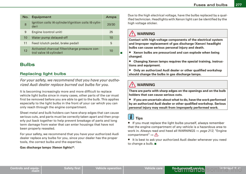
No. II Equipment Amps
8
Ignition coils (4 -cylinder)/ignition coils (6 -cylin -20/30 der)
-
9 Engine (control unit) 25
Water pump delayed-off 10
11 Feed (clutch pedal, brake pedal) 5
12
Activated charcoal filter/charge pressure con-10 trol valve (4-cylinder)
--
Bulbs
Replacing light bulbs
For your safety, we recommend that you have your autho
rized Audi dealer replace burned out bulbs for you.
It is becoming increasingly more and more difficult to replace
vehicle light bulbs since in many cases, other parts of the car must
first be removed before you are able to get to the bulb. This applies
especially to the light bulbs in the front of your car which you can
only reach through the engin e compartment .
Sheet metal and bulb holders can have sharp edges that can cause
serious cuts, and parts must be correctly taken apart and then prop
erly put back together to help prevent breakage of parts and long
term damage from wa ter that can enter housings that have not
been properly resealed.
For your safety , we recommend that you have your authorized Audi
dealer replace any bulbs for you, since your dealer has the proper
tools, the correct bulbs and the expertise.
Gas discharge lamps (Xenon lights)*:
•
Due to the high electrical voltage, have the bulbs replaced by a qual
ified technician. Headlights with Xenon light can be identified by the
high voltage sticker.
& WARNING
Contact with high-voltage components of the electrical system
and improper replacement of gas discharge (Xenon) headlight
bulbs can cause serious personal injury and death.
• Xenon bulbs are pressurized and can explode when being
changed.
• Changing Xenon lamps requires the special training, instruc
tions and equipment .
• Only an authorized Audi dealer or other qualified workshop
should change the bulbs in gas discharge lamps.
& WARNING
There are parts with sharp edges on the openings and on the bulb holders that can cause serious cuts.
• If you are uncertain about what to do, have the work performed
by an authorized Audi dealer or other qualified workshop. Serious
personal injury may result from improperly performed work.
[ i] Tips
• If you must replace the light bulbs yourself, always remember
that the engine compar tment of any vehicle is a hazardous area to
work in. Always read and heed all WARNINGS =>
page 212, "Engine
compartment"=> &.
• It is best to ask your authorized Audi dealer whenever you need
to change a bulb. •
Do-it-yourself service
Page 281 of 316

________________________________________________ E_ m_ e_r ,,::g c..e_ n _ c..::y;._ s_ i_t _u _a_ t_ i_o _n_ s _ ___.ffllll
& WARNING !continued)
• Before you check anything in the engine compartment, always
read and heed all WARNINGS~ page 212, "Engine compartment".
0 Note
• Applying a higher voltage booster battery will cause expensive
damage to sensitive electronic components, such as control units,
relays, radio, etc .
• There must be no electrical contact between the vehicles as
otherwise current could already start to flow as soon as the positive
(+) terminals are connected.
[ i) Tips
The discharged battery must be properly connected to the vehicle's
electrical system. •
Use of jumper cables
Make sure to connect the jumper cable clamps in exactly
the order described below!
Fig. 182 For jump
starting or charging
the battery, there is a
jump start connection
on the left side of the
engine compartment . Fig. 183 Jump
start
using the battery in
another vehicle: A -
Discharge, B-Female
socket
On vehicles with the 6-cylinder engine, instead of the
battery, on the left side of the engine compartment there is
a
Jump start connection=:> fig. 182. For jump starting, open
the cover on the positive terminal.
Preparatory measures
1. Do not jump start a frozen battery! Replace such a
battery!
2. Otherwise apply the hand brake and shift into idle gear if
your vehicle has manual transmission, and put the
selector lever into P position if your vehicle has auto
matic transmission.
3. For both vehicles switch off all consumers and the igni
tion.
Connecting/disconnecting the jumper cable.
4. Connect one end of the red jumper cable to the positive
terminal
G) =:> fig. 183 in the external starting point@ of
your vehicle .
5. Connect the other end of the red jumper cable to the
positive terminal
® of the booster battery®·
Vehicle care Do-it-yourself service irechnical data
Page 283 of 316

________________________________________________ E_ m_ e_r ,,::g c..e_ n _ c..::y;._ s_ i_t _u _a_ t_ i_o _n_ s _ ___._
Emergency towing with commercial
tow truck
General hints
Your Audi requires special handling for towing.
The following information is to be used by commercial tow truck
operators who know how to operate their equipment safely.
• Never tow your Audi, towing will cause damage to the engine
and transmission.
• Never wrap the safety chains or winch cables around the brake
lines.
• To prevent unnecessary damage, your Audi must be transported
with a car carrier (flatbed truck).
• To load the vehicle on to the flat bed, use the towing loop found
in the vehicle tools and attach to the front or rear anchorage
=> page 281 and=> page 282.
& WARNING
A vehicle being towed is not safe for passengers. Never allow
anyone to ride in a vehicle being towed, for any reason. •
Front towing loop
Do not install the front towing loop until it is needed.
Fig. 184 Front
bumper: removing the
grill
Fig . 185 Front
bumper: screwing
in
the towing loop
The towline eye fits into the threaded hole located on the
right side of the front bumper behind the grill.
- Remove the screwdriver and towing loop from the
vehicle toolkit=>
page 262.
-Insert the screwdriver into the slot as shown and press
toward the center of the vehicle => fig. 184. At the same
time, pull the grill forward and out.
- Screw the towing loop tightly into the threaded hole as
far as it will go => fig. 185.
~
Vehicle care Do-it-yourself service irechnical data
Page 285 of 316

________________________________________________ E_ m_ e_r ,,::g c..e_ n _ c..::y;._ s_ i_t _u _a_ t_ i_o _n_ s _ ___.lftll
Rear hook up
- Align the vehicle with the centerline of the car carrier
ramp.
- Attach the winch hook to the rear towline eye previously
insta lled.
[ i] Tips
Check carefully to make sure the hook-up is secure before moving
the car up the flatbed truck ramp. •
Lifting vehicle
Lifting with workshop hoist and with floor
jack
The vehicle may only be lifted at the lifting points illus
trated.
Fig . 188 Rear lifting
point (right side)
- Read and heed WARNING =>& .
Fig. 189 Front lifting
point (right side)
-Locate lifting points=> fig. 188 => fig. 189.
- Adjust li fting arms of workshop hoist or floor jack to
match vehicle lifting points.
- Insert a rubber pad between the floor jack/workshop
hoist and the lifting points.
If you must lift your vehicle with a floor jack to work underneath, be
sure the vehicle is safely supported on stands intended for this
purpose.
Front lifting point
The lifting point is located on the floor pan reinforcement about at
the same level as the jack mounting point=> fig. 189.
Do not lift the
vehicle at the vertical sill reinforcement.
Rear lifting point
The lifting point is located on the vertical reinforcement of the lower
sill for the on board jack=> fig. 188.
Lifting with vehicle jack
Refer to => page 269.
Vehicle care Do-it-yourself service Technical data
Page 287 of 316

________________________________________________ E _m_ e_r.:g :;,. e_ n_c ...: y:.- s_ i_ t _u _a_ t_ i_ o _ n_ s __ ffllll
• Do-it -yourself service
Page 291 of 316

_________________________________________________ G_ e_ n_ e_r _a _l_ i_n _f_o _ r_ m_ a_ t _i _o _ n __ lftlll
vehicle identification number of your vehicle (perforation) as well as
the Gross Vehicle Weight Rating (GVWR) and the Gross Axle Weight
Rating (GAWRl.
The high voltage warning label
is located on the lock carrier.
The spark ignition system meets all requirements of the Canadian
Interference-Causing Equipment Regulations. •
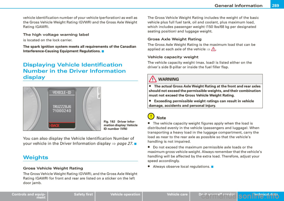
Displaying Vehicle Identification
Number in the Driver Information
display
Fig . 192 Driver Infor
mation display: Vehicle
ID number (VIN)
You can also display the Vehicle Identification Number of
your vehicle in the Driver Information display=:>
page 27. •
Weights
Gross Vehicle Weight Rating
The Gross Vehicle Weight Rating (GVWR), and the Gross Axle Weight
Rating (GAWR) for front and rear are listed on a sticker on the left
door jamb.
Controls and equip ment Safety first Vehicle operation
The
Gross Vehicle Weight Rating includes the weight of the basic
vehicle plus full fuel tank, oil and coolant, plus maximum load,
which includes passenger weight (150 lbs/68 kg per designated
seating position) and luggage weight.
Gross Axle Weight Rating
The Gross Axle Weight Rating is the maximum load that can be
applied at each axle of the vehicle~&.
Vehicle capacity weight
The vehicle capacity weight (max. load) is listed either on the
driver's side 8 -pillar or inside the fuel filler flap.
& WARNING
• The actual Gross Axle Weight Rating at the front and rear axles
should not exceed the permissible weights, and their combination
must not exceed the Gross Vehicle Weight Rating.
• Exceeding permissible weight ratings can result in vehicle
damage, accidents and personal injury.
0 Note
• The vehicle capacity weight figures apply when the load is
distributed evenly in the vehicle (passengers and luggage). When
transporting a heavy load in the luggage compartment, carry the
load as near to the rear axle as possible so that the vehicle's
handling is not impaired.
• Do not exceed the maximum permissible axle loads or the
maximum gross vehicle weight. Always remember that the vehicle's
handling will be affected by the extra load. Therefore, adjust your
speed accordingly.
• Always observe local regulations. •
Vehicle care Do-it-yourself service Tec hn ica l da ta
Page 293 of 316

_______________________________________________________ D_ a _ t_a __ llll
Data
A pplie s t o vehic les: w it h 2 .0 lit er 4-cy l. engi ne
200 hp, 2.0 liter 4-cyl. turbo engine
Engin e da ta
Maximum output SAE net
Maximum torque SAE net
No . of cylinders
Displacement
Stroke
Bore
Compression ratio
Fuel
Dim ension s (app rox.)
Length (with licence plate bracke t)
Width (across mirrors)
Height (unloaded)
Turning circle diameter (curb to curb)
Ca pac ities (a pprox.)
F u el t ank
-Total capacity
- Reserve (of total capacity)
Wind shi eld and he adli ght * was her fluid container
E ngine oil
with filter change
Controls and equip
ment Safety first
hp@rpm
lb-ft@ rpm
CID (cm
3
)
in (mm)
in (mm)
200@ 5100 -6000
207 @ 1800 -5000
4
121 (1984)
3.65 (92.8)
3 .25 (82.5)
10.3 : 1
Premium unleaded (91 AKI) Recommended for maximum engine performance. Fur
ther details =>
page 274, "Gasoline"
in (mm)
in (mm)
in (mm)
ft. (ml
164 .5 (4178)
76.9 (1952) 53 .2 (1352)
34 .7 (10.60)
gal/litres
gal/litres
quarts/litres
quarts/l itres 14.5 / 55 .0
1 .9 / 7.0
4.3
I 4.0
4.8
I 4.5 •
Vehicle operation Vehicle care Do-it-yourself service Tec hn ica l da ta