2008 AUDI TT ROADSTER transmission
[x] Cancel search: transmissionPage 241 of 316
________________________________________________ T_ i _r_e _s_ a_n_ d_ w_ h_ e_e _ l_s __ l'III
•
& W ARNING (continu ed )
crashes and serious personal in jur ies . Have worn or da maged t ires
replaced immediately .
• Tires age even if they are not being u sed and can fail suddenly ,
especially at high speeds. T ires that are more than 6 years old can
only be used in an emergency and then w ith special care and at
low speed.
Glossary of tire and loading terminology
Accessory weight
means the co mbined we ig ht ( in excess o f those sta nda rd items
which may be rep laced) of automatic transmission, power steering,
power brakes, power w indows, powe r seats, rad io, a nd heater, to
the extent that these items are avai lab le as factory-installed equip
m ent (w hether insta lled or not).
Aspect ratio means t he ratio o f th e height to t he w idt h of the tire in perce nt.
N umbers of 55 or lower indicate a low sidewa ll for improved
steer ing respo nse and b ette r overall ha ndl ing on dry pave ment.
Bead
means the part of the tire that is made of stee l wires, wrapped or
reinforced by ply cords and that is shaped to fit the rim.
Bead separation
means a breakdow n of the bond be tween co mponents i n the bead.
Cord
m eans the strands fo rmi ng the plies in the ti re.
& W ARNING (continued )
• Never mount used tires on your vehicle if you are not sure of
their "previous history. " Old used t ire s may ha ve been damaged
even though the damage cannot be seen that can lead to sudden
tire failure and lo ss of vehicle control.
• If you noti ce unusual vibration or if the vehicle pulls to one side
when driving , always stop as soon as it is safe to do so and check
the wheels and tires for damage . •
Cold tire inflation pressure
mea ns t he ti re pressure reco mm ended by the ve hicle ma nufacturer
for a tire of a designated size that has not been d riven for more tha n
a cou ple o f miles (k ilometers) at low speeds in t he t hre e ho ur per iod
before the tire pressure is measured or ad justed .
Curb weight
means the weight of a moto r vehic le with standard equipment
i nc lud ing the max imu m capac ity o f fue l, o il, and coola nt, a ir c ond i
tioning and additiona l weight of optional equipment.
Extra load tire
means a tire designed to ope rate at higher loads and at higher infla
tion pressures than the corresponding standard tire. Extra load tires
my be identified as "XL", "xi", "EX TRA LOAD", or "RF" on the side
wa ll.
Gross Axle Weight Rating ("GAWR ")
means the load -carrying capacity of a sing le ax le system, measured
at the ti re -ground interfaces.
Gross Vehicle Weight Rating ("GVWR "l
mea ns the ma ximum tot al l oade d weigh t of the vehicle.
Vehicle care
I t •
Page 266 of 316
1111...__W_ h_ a _ t_d_ o_ l _d _o_ n_ o_ vv_ ? ______________________________________________ _
& WARNING (continued)
-if you have been driving with very low tire pressures or tires
with no air
• Seek professional assistance if it is not possible to repair the
tire with the tire sealant.
& WARNING
The tire sealant must not come into contact with skin, eyes or
clothing.
• If you get any tire sealant
in your eyes or come into contact
with it, rinse the affected area thoroughly with clean water. Find a physician immediately!
• Change any clothing contaminated with tire sealant immedi
ately.
• Do not inhale the vapor!
• If you have swallowed tire sealant, rinse your mouth thor
oughly right away and drink plenty of water .
- Do not induce vomiting! Find a physician immediately!
• If you have allergic reactions, find a physician immediately .
• Keep the tire sealant away from children .
0 Note
Do not use commercially available tire sealants. The electrical
components of the tire pressure monitoring system will no longer
work properly.
'i> For the sake of the environment
Used sealant bottles can be dropped off at a recycling facility.
[ i] Tips
• If sealant has run out, allow it to dry. Then you can peel it off.
• Have the tire sealant replaced every 4 years at a dealership. •
Applies to vehic les: with T ire Mob ility System
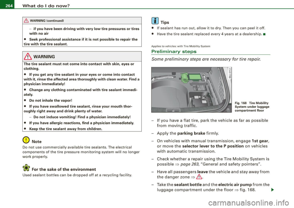
Preliminary steps
Some preliminary steps are necessary for tire repair .
Fig. 168 Tire Mobility
System under luggage
compartment floor
- If you have a flat tire, park the vehicle as far as possible
from moving traffic.
- Apply the
parking brake firmly.
- On vehicles with manual transmission, engage
1st gear,
or move the selector lever to the P position on vehicles
w ith automatic transmission.
- Check whether a repair using the Tire Mobility System is
possible~
page 263, "General and safety pointers".
Have all passengers
leave the vehicle and stay away from
the danger zone~&.
- Take the
sealant bottle and the electric air pump from the
luggage compartment under the floor ~ fig. 168. .,_
Page 277 of 316

Fuses and bulbs -
----------------
Equipment No. Equipment
Amps
Engine relay, fuel tank control unit, Airbag Off
16 A/C system (control unit) 10
1
light, light switch (switch illumination), diagnos-10
tic connector
17 Tire pressure monitoring system (control unit) 5
18
Not used
ABS, ASR, ESP, brake light switch
5 19
Not used
3 AFS headlight (left) 5
Not used
Oil level sensor (extended maintenance interval)
(WIV), tire pressure monitoring system, switch
21 Fuel injectors (gasoline engine) 10
4 for Electronic Stability Program (ESP), AFS head-5 Wind deflector (Roadster) 30
lights (control unit), A/C system (pressure sen -23 Horn 20 sorl, backup light switch
Automatic headlight range control, AFS head-
24 Transmission (control unit) 15
5
light (right)/ manual headlight range control, 5/10
25 Heater rear window Coupe/heated rear window 30/20
halogen headlights Roadster
Control unit for CAN data transfer (gateway),
26 Driver's side power window 30
6 electromechanical steering, automatic transmis-5
27 Passenger's side power window 30
sion shift gate
28 Not used
Acoustic Park Assist, automatic dipping interior
rear view mirror, garage door opener, heatable
29 Washer pump 15
7
windshield washer nozzles, washer pump, wind 5
30 Cigarette lighter 20
deflector relay (Roadster)
31 Starter 40
8
Haldex clutch 5 32 Steering column module 5
9
Control unit Audi magnetic ride 5 33
Instrument cluster 5
Airbag control unit 5 34 Radio navigation system, radio 15
1 1 Mass airflow sensor, crankcase heating 5/10
35
Audio amplifier 30
12 Door control unit (central locking driver/passen-10
36 Engine (control unit) 10 ger)
13 Diagnostic connector 10 37 CAN (Gateway) 5
Rain sensor, automatic transmission shift gate 5 38 Not used
15 Roof
light (interior lighting) 5 39 Not used
• Do-it
-yourself service
Page 281 of 316

________________________________________________ E_ m_ e_r ,,::g c..e_ n _ c..::y;._ s_ i_t _u _a_ t_ i_o _n_ s _ ___.ffllll
& WARNING !continued)
• Before you check anything in the engine compartment, always
read and heed all WARNINGS~ page 212, "Engine compartment".
0 Note
• Applying a higher voltage booster battery will cause expensive
damage to sensitive electronic components, such as control units,
relays, radio, etc .
• There must be no electrical contact between the vehicles as
otherwise current could already start to flow as soon as the positive
(+) terminals are connected.
[ i) Tips
The discharged battery must be properly connected to the vehicle's
electrical system. •
Use of jumper cables
Make sure to connect the jumper cable clamps in exactly
the order described below!
Fig. 182 For jump
starting or charging
the battery, there is a
jump start connection
on the left side of the
engine compartment . Fig. 183 Jump
start
using the battery in
another vehicle: A -
Discharge, B-Female
socket
On vehicles with the 6-cylinder engine, instead of the
battery, on the left side of the engine compartment there is
a
Jump start connection=:> fig. 182. For jump starting, open
the cover on the positive terminal.
Preparatory measures
1. Do not jump start a frozen battery! Replace such a
battery!
2. Otherwise apply the hand brake and shift into idle gear if
your vehicle has manual transmission, and put the
selector lever into P position if your vehicle has auto
matic transmission.
3. For both vehicles switch off all consumers and the igni
tion.
Connecting/disconnecting the jumper cable.
4. Connect one end of the red jumper cable to the positive
terminal
G) =:> fig. 183 in the external starting point@ of
your vehicle .
5. Connect the other end of the red jumper cable to the
positive terminal
® of the booster battery®·
Vehicle care Do-it-yourself service irechnical data
Page 283 of 316

________________________________________________ E_ m_ e_r ,,::g c..e_ n _ c..::y;._ s_ i_t _u _a_ t_ i_o _n_ s _ ___._
Emergency towing with commercial
tow truck
General hints
Your Audi requires special handling for towing.
The following information is to be used by commercial tow truck
operators who know how to operate their equipment safely.
• Never tow your Audi, towing will cause damage to the engine
and transmission.
• Never wrap the safety chains or winch cables around the brake
lines.
• To prevent unnecessary damage, your Audi must be transported
with a car carrier (flatbed truck).
• To load the vehicle on to the flat bed, use the towing loop found
in the vehicle tools and attach to the front or rear anchorage
=> page 281 and=> page 282.
& WARNING
A vehicle being towed is not safe for passengers. Never allow
anyone to ride in a vehicle being towed, for any reason. •
Front towing loop
Do not install the front towing loop until it is needed.
Fig. 184 Front
bumper: removing the
grill
Fig . 185 Front
bumper: screwing
in
the towing loop
The towline eye fits into the threaded hole located on the
right side of the front bumper behind the grill.
- Remove the screwdriver and towing loop from the
vehicle toolkit=>
page 262.
-Insert the screwdriver into the slot as shown and press
toward the center of the vehicle => fig. 184. At the same
time, pull the grill forward and out.
- Screw the towing loop tightly into the threaded hole as
far as it will go => fig. 185.
~
Vehicle care Do-it-yourself service irechnical data
Page 286 of 316

lllffl.___E_ m _ e _r-==g :...e_ n_ c...:y _ s_ i_t _u _a _t_ i_o _n_ s _______________________________________________ _
& WARNING
• To reduce the risk of serious injury and vehicle damage .
- Always lift the vehicle only at the special workshop hoist and
floor jack lift points illustrated
~ page 283, fig. 188 and
~ page 283, fig. 189.
- Failure to lift the vehicle at these points could cause the
vehicle to tilt or fall from a lift if there is a change in vehicle
weight distribution and balance. This might happen, for
example, when heavy components such as the engine block or
transmission are removed.
• When removing heavy components like these, anchor vehicle
to hoist or add corresponding weights to maintain the center of
gravity. Otherwise, the vehicle might tilt or slip off the hoist,
causing serious personal injury.
0 Note
• Be aware of the following points before lifting the vehicle:
- The vehicle should never be lifted or jacked up from under
neath the engine oil pan, the transmission housing, the front or
rear axle or the body side members . This could lead to serious
damage.
- To avoid damage to the underbody or chassis frame, a rubber
pad must be inserted between the floor jack and the lift points.
- Before driving over a workshop hoist, check that the vehicle
weight does not exceed the permissible lifting capacity of the hoist .
- Before driving over a workshop hoist, ensure that there is sufficient clearance between the hoist and low parts of the
vehicle. •
Page 290 of 316

___ G_ e_ n_ e_r_ a _ l_ in_ f_ o _r_m _ a_ t_ i_ o _ n __________________________________________________ _
General information
Explanation of technical data
Some of the technical data listed in this manual require
further explanation .
The tecical data for your vehicle are listed in the charts starting on
~ page 291 . This chapter provides general information, notes and
restrictions which apply to these data. •
Vehicle identification
The key data are given on the vehicle identification
number (VIN) plate an d the vehicle d ata sticker.
Fig. 19 0 Vehicl e Identi
fi ca tion N umber (V IN)
pl ate : lo cation on
dri ver 's s ide d ash
pan el F
ig . 19 1 Th e vehi cle
i d e ntifi catio n la bel -
i n sid e th e luggag e
com partm ent
The Vehicle Id ent ification Numb er (V IN)
is located on the driver's side so that it is visible from the outside
through the winds hie ld -see ~ fig. 190 .
The veh icle identifi cat ion lab el
is located in the luggage compar tment in the spare whee l well .
The label~ fig. 191 shows the following vehic le data :
0 Production contro l No.
0 Vehicle identification No .
G) Type code number
© Type designation/engine output in Ki lowatts
@ Engine and transmission code letter
© Paint No./lnterior
0 Optiona l equipment No.'s
Vehicle data 2 to 7 are also found in your Maintenance
& Warranty
booklet.
Th e s afety c ompliance sticker
is your assurance that your new vehicle complies with a ll app licable
Federa l Motor Vehicle Safety Standards which were in effect at the
time the vehicle was manu factured. You can find this sticker on the
left door jamb . It shows the month and year of production and the .._
Page 297 of 316

_______________________________________________ C _o_ n _ s_u _ m_ e_ r_l_n _f_o _ r_ m_ a_ t _i _o _ n __ _
workshop personne l in order to assure proper performance, reli
abil ity and sa fe ty of the vehicle a nd i ts many sys te m s.
I mproper maintenance, adjustments and repairs can impair the
operation and reliabil ity of your vehicle and even void your vehicle
war ra nty. T here fore, proof o f serv ic ing in accorda nce with the main
tenance schedule may be a condition for uphold ing a possible
war ra nty claim made withi n th e warranty per iod .
Above all, operat ional safety can be adverse ly affected, creating
unnece ssary risks fo r you and you r passengers .
If in doubt about a ny servici ng, have it do ne by your authorized Aud i
dea ler or any other properly equipped and qua lified workshop. We
str ongly u rge you to give your auth orized Audi dealer the oppo rtu
nity to perform al l scheduled maintenance and necessary repairs.
You r deale r has the facil ities, origi nal par ts and trained special is ts
to keep your vehic le running proper ly.
Performing limited maintenance yourself
T he fo llow ing pages describe a limited numbe r of procedures which
can be perfo rme d on you r vehicle wi th ordi nary too ls, should the
need arise and trained personne l be unavailab le. Before performing
any of these proced ures, always thor oug hly read a ll of th e appli
cable text and carefu lly fo llow the instructions given. Always rigor
ously observe the
WARNINGS provided .
Before you check anything in the engine compartment , alway s read
and heed all WARNINGS:::>
& and:::> & in "Wo rking in the engine
compartment" on
page 220.
& WARNING
• Ser ious persona l injury may occur as a result of improperly
performed maintenance , adjustments or repairs.
• Always be e xtremely careful when working on the vehicle .
Always follow commonly accepted safety practices and general
c ommon sense . Never ri sk per sonal injury .
Controls and equip ment Safety first Vehicle operation
& W
ARNING (continued )
• Do not attempt any of the maintenance , checks or repairs
described on the following pages if you are not fully familiar with
these or other pro cedures with respect to the vehicle , or are uncer
tain how to proceed.
• Do not do any work without the proper tools and equipment.
Have the necessary work done by your autho rized Audi dealer or
another properly equipped and qualified workshop .
• The engine compartment of any motor vehicle is a potentially
hazardous area . Never reach into the area around or touch the
radiator fan . It i s temperature controlled and can switch on
suddenly -even when the engine is off and the ignition key has
been removed . The radiator fan switche s on automatically when
the coolant reaches a certain tempe rature and will continue to run
until the coolant temperature drops .
• Always remove the ignition key before anyone gets under the
vehicle.
• Always support your vehicle with safety stands if it is neces
sary to work underneath the vehicle. The jack supplied with the
vehicle is not adequate for this purpose and could collapse
causing serious personal injury .
• If you must work underneath the vehicle with the wheels on
the ground, always make sure the vehicle is on level ground , that
the wheels are always securely blocked and that the engine
cannot be started .
• Always make sure the transmission selector lever (automatic
transmission) is in "P" (Park position ) (automatic transmission ) or
Neutral (manual tr ansm ission) and the hand brake is firmly
applied.
levels. This is detrimenta l to the environment and increases fuel
co nsu mp tion.
Vehicle care Do-it-yourself service Tec hn ica l da ta