2008 AUDI TT ROADSTER warning light
[x] Cancel search: warning lightPage 247 of 316
________________________________________________ T_ i _r_e _s_ a_n_ d_ w_ h_ e_e _ l_s __ _
•
pressure for a trip - even one that you would not consider to be
"long." See=>
page 246, "Tires and vehicle load limits" for more
important information .
Always use an accurate tire pressure gauge when checking and adjus ting inflation pressures . Check all of the tires and be sure not
to forget the spare tire . If the pressure in any tire is too high when
the tire is "cold," let air out of the tire slowly with the edge of the tire gaug e and keep checking the pressur e until you reach the pressure
that is correct for the load (passengers and luggage) and kind of driving you plan to do.
I f the pressure in any tire is too low, note the difference between the
pressure in the cold tire and the pressure you need and add the air
that you need to reach the correct pressure for the vehicle load
(passengers and luggage) for the tires on your vehicle as listed on
the on your vehicle and in this manual and the kind of driving you
plan to do.
Ne ver e xceed the m aximum inflat ion pre ssure l isted on the tire
sid ewall for any rea son .
Remember that the veh ic le manufacturer, not the tire manufacturer ,
determin es the correct tire pressure for the tires on your vehicle .
It is important to check the tire pressure when the tires are cold .
• Read the required tire pressure from the tire pressure label
located on driver 's side 8 -pillar.
• T urn the va lve stem cap counter -clockwise to remove it from the
tire valve .
• Place the air pressure gauge on the valve .
• The tire pressures should only be checked and adjusted when
the tires are cold. The s lightly raised pressures of warm tir es mus t
not be reduced.
• Adjust the tire pressure to the load you are carrying .
• Reinstall the va lve stem cap on the valve .
When should I ch eck the tir e pr essu re?
The correct tire pressure is especially important a t high speeds . The
pressure should therefore be checked a t least once a month and
a lways before sta rting a journey.
Wh en sho uld I adjust the tire p re ss ure s?
Adjust the tire pressure to the load yo u are carrying . After changing
a wheel
o r replacing wheels you have to adjust the tire pressures on
a ll whee ls . In addition, you must then initia lize the new tire pres
sures in the tire pressure monitoring system=>
page 41.
& WARNING
Incorre ct t ir e pre ssures and /or underinfl ati on ca n lead sudden tire
failure , los s of contro l, colli sion , seriou s per sonal injury or even
death .
• Whe n the w arnin g sy mbol appear s in the instrument
cl uster , sto p and in spe ct the tire s.
• Inco rre ct tire pre ssure and /or underin flati on can cau se
in creased tire wear and can affe ct the ha ndling of the vehicle and
s topping ability.
• Incorre ct t ire pre ssures and /or underinfl atio n c an a ls o le ad to
s udden tire f ailure , including a blowout and sudden deflation ,
ca usi ng loss o f vehi cle co ntrol.
• The driv er i s re sp o nsible for the correct tire p re ss ure s for all
tire s on the vehicle . T he appl icable pre ssure v alu es are lo ca ted o n
a stic ker on th e driver 's side B -pillar.
• Onl y w hen all tire s on th e veh icle a re fi lled to the corre ct pre s
s ure , the tire pre ssure monitor ing sy ste m can work correctly .
• The u se of incorre ct t ire pr essure val ues can lead to accidents
or other d am age. The refo re it is esse ntial th at the dri ver ob serve
the spe cified tire pr essur e value s fo r the t ire s and the correc t pr es
s ures for the function of the tire pr essure monitoring sy stem.
• Always inflate t ires to the r ecom mended and corre ct tir e pr es -
su re bef ore dri ving off.
~
Vehicle care I t •
Page 261 of 316
________________________________________________ T_ i _r_e _s_ a_n_ d_ w_ h_ e_e _ l_s __ lfll
•
Handling characteristi cs change wh en dri ving with
low air pressure or with flat tires even with special run
flat tires
A low pressure or flat front tire affects vehicle hand lin g charac te ri s
t ics by pulling the vehic le slightly to the side where the tire is
mounted and reduces brak ing performance .
A low pressure or flat
rear tire also affec ts driving c haracteristics by
pul ling to the side where th e tire is mounted and also reduces
b raki ng per for mance . T he ef fec t o n ve hic le han dlin g is most n otice
able when driving around curves .
& WARNING
Changed vehicle handling characteristics when driv ing in the run
flat mode can cause lo ss of vehicle control , a crash and serious
personal injury .
• Driving on special run-flat tires in the run -flat mode will change
vehicle handling characterist ics during braki ng , when cornering
and under heavy acceleration .
• Never drive faster than the max imum rated speed of 50 mph
(80 km /h) when driving in the run -flat mode .
• Always adjust vehicle speed to traffic , road and weather condi
tions and drive slower than the maximum rated speed if nece ssary
weather and road conditions are taken into ac count .
• Always obey speed limits and other traffic laws .
0 Note
We always recommend driv ing with even more care when using
these special tires in the run -flat mode. A lways avoid sudden
m aneuvers. •
Applies to vehic les: with Run-f lat tires
Replacing run -flat tires and rims
Y our vehicle was especi ally des igned to use special run
fl at t ires.
You may use and c ombi ne o nly approved run -flat t ires a nd specia l
matching rims that have been designed for run -flat tires. Mounting
special run -fla t tires o n stan dard wheels w ill not work and wi ll not
provide the advantages fo the run -falt feature. Never us e special
run-flat tir es o n standard whee l rims.
After driving with a tire in the run -f lat mode, always have the vehicle
and affected tire(s) and rim(s) inspected by an a uthorized Audi
dea ler. T ires tha t have been driven i n the run -fla t mode mus t be
replaced.
& WARNING
Use of damaged run-flat tires and rims c an cause vehicle damage
that can lead to loss of vehicle control , a crash and serious
personal injury.
• Always have the vehi cle and affected tire (sl and rim(s )
inspe cted by an authorized Audi dealer after driving a tire in the
run -flat mode .
• Tires that have been driven in the run -flat mode must be
repla ced .•
Vehicle care
I t •
Page 267 of 316
_______________________________________________ W_ h_ a _ t_d_ o_ l _d _o_ n_ o_ w_ ? _ __.1111
- Remove the "max. 50 mph" (80 km/h) sticker from the
sealant bottle and affix it to the instrument cluster in the
driver's view.
& WARNING
• Turn the hazard flashers on and set up the warning triangle if
you have a flat tire in moving traffic . In this way you protect your
self and other road users.
• Make sure that all passengers are in a safe place, out of the
danger zone (for example, behind a guard rail).
0 Note
Particular care is necessary if you are making a tire repair on a steep
incline.
[ i] Tips
Obey all laws. •
Applies to vehicles: with T ire Mobil ity System
Making a tire repair
Tire repair consists of the following sections.
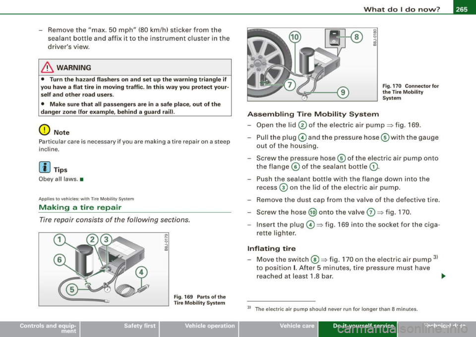
Fig. 169 Parts of the
Tire Mobility System Fig
. 170 Connector for
the Tire Mobility System
Assembling Tire Mobility System
- Open the lid 0 of the electric air pump~ fig. 169.
- Pull the plug© and the pressure hose G)with the gauge
out of the housing.
- Screw the pressure hose© of the electric air pump onto
the flange © of the sealant bottle
G).
- Push the sealant bottle with the flange down into the
recess
G) on the lid of the electric air pump.
- Remove the dust cap from the valve of the defective tire.
- Screw the hose @) onto the valve
G) ~ fig. 170.
- Insert the plug©~ fig. 169 into the socket for the ciga-
rette lighter.
Inflating tire
- Move the switch®~ fig. 170 on the electric air pump 31
to position I. After 5 minutes, tire pressure must have
reached at least 1.8 bar.
~
3> The e lectric air pump should never run for longer than 8 minutes.
Vehicle care Do-it-yourself service irechnical data
Page 268 of 316
11111.___W_ h_ a _ t_d_ o_ l _d _o_ n_ o_ w_ ? ______________________________________________ _
- Switch the electric air pump off - switch in position
0. If
the required tire pressure of at least 1.8 bar has not been
reached, follow the instructions in the section Re
inflating tire.
Re-inflating tire
-Remove the hose from the valve and pull the plug out of
the socket.
- Drive the vehicle slowly 10 meters backward or forward.
This helps to distribute the sealant better.
- Remove the empty inflation bottle and screw the hose
G)
=> page 265, fig. 169 from the electric pump directly onto
the valve.
- Insert the plug ©=>
page 265, fig. 169 into the socket for
the cigarette lighter.
- Move the switch
@ => page 265, fig. 170 on the electric
air pump
31 to position I. After 5 minutes, tire pressure
must have reached at least
1 .8 bar.
- Switch the electric air pump off - switch in position
0. If
the required tire pressure of at least 1.8 bar has not been reached, it is not possible to make a repair with the tire
sealant. Seek professional assistance.
Disassembling Tire Mobility System
- Remove the hose from the valve and pull the plug out of
the socket.
- Screw the dust cap onto the valve.
- Place the empty sealant bottle back in the original pack-
aging and cl ip it in place under the floor so that no tire
sealant can run out into t he vehicle. -
Place the electric air pump in the luggage compartment
for the time being.
- Start driving right away so that the sealant is distributed
in the tire.
& WARNING
• Follow the manufacturer's safety instructions on the decal for
the air pump and the sealant bottle.
• If a tire pressure of 1.8 bar cannot be achieved after pumping
for 5 minutes, the tire is too severely damaged. Do not continue to
drive.
• Seek professional assistance if it is not possible to repair the
tire with the tire sealant.
[ i] Tips
• Do not operate the electric air pump for more than 8 minutes
without stopping, otherwise it can overheat. When the air pump has
cooled down, you can continue to use it.
• If sealant has escaped, allow it to dry, then you can peel it off. •
Applies to vehic les : with Tire Mobil ity Sys tem
Final check
After driving for a short distance , tire pressure
must be checked
- After driving for about 10 minutes, stop and check the
tire pressure .
- If tir e pressure is still at least 1.3 bar, inflate the tire to
specified pressure (see driveas side B -pillarl, drive to the
next repair shop and have the tire and the sealant bottle
replaced.
~
Page 273 of 316

What do I do now? -
----------------
•
-Screw the threaded end of the alignment pin from the
tool kit hand-tight into the now vacant bolt hole
=:> page 270, fig. 177.
- Then completely unscrew the other wheel bolts as
described above.
- Take off the wheel leaving the alignment pin in the bolt
hole.
Putting on the wheel
- Lift the spare wheel and carefully slide it over the align
ment pin to guide it in place.
- Use the hexagonal socket in the screwdriver handle to
screw in and tighten all wheel bolts slightly.
- Unscrew the alignment pin and insert and tighten the
remaining wheel bolt slightly like the rest.
- Turn the jack handle counter -clockwise to lower the
vehicle until the jack is fully released.
- Use the wheel bolt wrench to tighten all wheel bolts
firmly =:> page 268. Tighten them crosswise, from one
bolt to the (approximately) opposite one, to keep the
wheel centered.
[ i J Tips
Never use the hexagonal socket in the handle of the screwdriver to
loosen or tighten the wheel bolts.
• Pull the reversible blade from the screwdriver before you use the
hexagonal socket in the handle to turn the wheel bolts.
• When mounting tires with
unidirectional tread design make sure
the tread pattern is pointed the right way~
page 272.
• The wheel bolts should be clean and easy to turn. Check for dirt
and corrosion on the mating surfaces of both the wheel and the
hub . Remove all dirt from these surfaces before remounting the
wheel. •
Notes on wheel change
Please read the information~ page 249, "New tires and replacing
tires and wheels", if you are going to use a spare tire which is
different from the tires on your vehicle.
After you change a tire:
• Check the tire pressure on the spare immediately after
mounting.
• Have the wheel bolt tightening torque checked with a torque
wrench as soon as possible by your authorized Audi dealer or a qualified service station .
• With steel and alloy wheel rims, the wheel bolts are correctly
tightened at a torque of 90 ft lb (120 Nml.
• If you notice while changing a tire that the wheel bolts are
corroded and difficult to turn, then they should be replaced before
you check the tightening torque.
• Replace the flat tire with a new one and have it installed on your
vehicle as soon as possible. Remount the wheel cover.
Until then, drive with extra care and at reduced speeds.
& WARNING
• If you are going to equip your vehicle with tires or rims which
differ from those which were factory installed, then be sure to read
the information
~ page 249, "New tires and replacing tires and
wheels".
• Always store the tools securely in luggage compartment.
Otherwise, in an accident or sudden maneuver they could fly
forward, causing injury to passengers in the vehicle.
Do-it-yourself service
Page 279 of 316
_______________________________________________ F_ u_ s _ e_s _ a _ n_d _ b_ u_ l_ b_ s __ ffllll
•
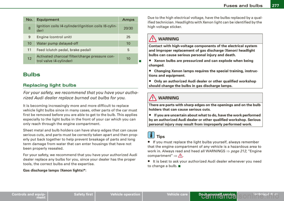
No. II Equipment Amps
8
Ignition coils (4 -cylinder)/ignition coils (6 -cylin -20/30 der)
-
9 Engine (control unit) 25
Water pump delayed-off 10
11 Feed (clutch pedal, brake pedal) 5
12
Activated charcoal filter/charge pressure con-10 trol valve (4-cylinder)
--
Bulbs
Replacing light bulbs
For your safety, we recommend that you have your autho
rized Audi dealer replace burned out bulbs for you.
It is becoming increasingly more and more difficult to replace
vehicle light bulbs since in many cases, other parts of the car must
first be removed before you are able to get to the bulb. This applies
especially to the light bulbs in the front of your car which you can
only reach through the engin e compartment .
Sheet metal and bulb holders can have sharp edges that can cause
serious cuts, and parts must be correctly taken apart and then prop
erly put back together to help prevent breakage of parts and long
term damage from wa ter that can enter housings that have not
been properly resealed.
For your safety , we recommend that you have your authorized Audi
dealer replace any bulbs for you, since your dealer has the proper
tools, the correct bulbs and the expertise.
Gas discharge lamps (Xenon lights)*:
•
Due to the high electrical voltage, have the bulbs replaced by a qual
ified technician. Headlights with Xenon light can be identified by the
high voltage sticker.
& WARNING
Contact with high-voltage components of the electrical system
and improper replacement of gas discharge (Xenon) headlight
bulbs can cause serious personal injury and death.
• Xenon bulbs are pressurized and can explode when being
changed.
• Changing Xenon lamps requires the special training, instruc
tions and equipment .
• Only an authorized Audi dealer or other qualified workshop
should change the bulbs in gas discharge lamps.
& WARNING
There are parts with sharp edges on the openings and on the bulb holders that can cause serious cuts.
• If you are uncertain about what to do, have the work performed
by an authorized Audi dealer or other qualified workshop. Serious
personal injury may result from improperly performed work.
[ i] Tips
• If you must replace the light bulbs yourself, always remember
that the engine compar tment of any vehicle is a hazardous area to
work in. Always read and heed all WARNINGS =>
page 212, "Engine
compartment"=> &.
• It is best to ask your authorized Audi dealer whenever you need
to change a bulb. •
Do-it-yourself service
Page 280 of 316
.,,___E_ m_ e_r -=g :...e_ n _ c-=y _ s_ i_t _u _a _t_ i_o _n_ s _______________________________________________ _
Emergency situations
General
This chapter is intended for trained emergen cy crew s and working
personnel who have the necessary tools and equ ipment to perform
the se operations. •
Starting by pushing or towing
0 Note
Vehicles with an automatic tran smission cannot be started by
pushing or towing . •
Starting with jumper cables
If n ecess ary, the e ngin e c an b e starte d by conne ctin g it to
the ba ttery of anoth er vehicle .
If the engine shou ld fai l to start because of a discharged or weak
ba tte ry, the bat te ry can be connected t o the ba ttery of
another
vehic le, using a pair of jumper cables to start the engine.
Jumper cables
Use
only jumper cables of suffic iently large cross section to safely
c a rr y th e st arter cu rre nt. Re fer to th e m an ufacture r's spec ific a tio ns.
Use on ly jump er cables wh ic h have
insulated termina l c lamps and
a re prope rly marked for distinction :
plus (+l cable in mo st cas es c olo red red
minus (-l cable in most cases co lored black .
& WARNING
Batteries contain electricity , acid , and gas . Any of these can cause
very serious or fatal injury. Follow the instructions below for safe
handling of your vehicle 's battery .
• Always shield your eyes and avoid leaning over the battery
whenever possible .
• A discharged battery can already freeze at temperatures just
below 32 °F (0 °Cl. Before connecting a jumper cable, the frozen
battery must be thawed completely , otherwise it could explode .
• Do not allow battery a cid to contact eyes or skin . Flush any
contacted area with water immediately.
• Improper use of a booster battery to start a vehicle may cause
an explosion.
• Vehicle batteries generate e xplosive gases . Keep sparks, flame
and lighted cigarettes away from batteries.
• Do not try to jump start any vehicle with a low ac id level in the
battery.
• The voltage of the booster battery must also have a 12-Volt
rating . The capacity (Ahl of the booster battery should not be
lower than that of the discharged battery . Use of batteries of
different voltage or substantially different "Ah " rating may cause
an e xplosion and personal injury .
• Never charge a frozen battery. Gas trapped in the ice may cause
an explosion .
• Never charge or use a battery that has been frozen . The battery
case may have be weakened.
• Use of batteries of different voltage or substantially different
capacity (Ah ) rating may cause an explosion and injury . The
capacity (Ahl of the booster battery should not be lower than that
of the discharged battery . .,_
Page 282 of 316

llll1.--___;E::. m :..:..:. e .::..:..r_,.g ~e:..: n:..:..: c:.!y ;__: s:... i..:.t ..:.u :...a ..:.t:... i..::o ..:.n..:.. s::.... ______________________________________________ _
6. Connect one end of the black jumper cable to the nega
tive term inal
0 of t he booster bat tery @.
7. Connect the other end of the balck jumper cable to the negative terminal (bolt head)
G) in the external starting
point @ of your ve hic le.
8. Route the jumper cables so tha t they cannot catch in any
rotating parts in the engine compartment.
Starting the engin e
9. Start the engine of the vehicle providing assistance and
allow it to run at id le.
10 . Now start t he engine o f the ve hicle wit h the disc harged
battery, wa it for two to three minutes until t he engine
"runs" smoothly.
11 . If the engi ne does not start : Stop tryi ng after 10 seconds
and t hen try ag ain after abo ut 30 secon ds.
12. In the vehicle that has received start assistance, turn on
the heate r blower and the rear window heating to elimi
nate any voltage pea ks when disconnecting. Driving
lights must be switched off!
1 3. Disconnect the cable while the engine is running exactly
in
reverse order to that described in=> page 279,
"Connecting/d isconnecting the jumper cable .". When
doing so, make sure t hat the cable cannot contact
rotating engine parts.
14 . Close the cover on the pos itive terminal.
The battery is vented to the outside to prevent gases from entering
the vehic le interior. Make sure that the jumper clamps are well
connected with their
metal parts in full contact with the battery
termina ls .
& WARNING
To a vo id se riou s pe rso nal in jur y a nd d am age t o the vehi cle, heed
all wa rnings and in stru ction s of th e jumper cable manuf acturer. If
i n doubt , call for r oad ser vic e.
• Jumper c able s mu st be long enough so that the vehicle s do not
t o uch .
• When connecting jumper cable s, make sur e th at they cannot
g et ca ught in any mo ving p arts in the eng ine comp artment .
• Bef ore you che ck anyth ing in the engin e comp artment , alway s
r ea d and heed all WARNING S=:,
page 21 2, "Engine c omp artment ".
0 Note
Improper hook -up of jumper cables can ruin the generator .
• Always connect POS ITIVE ( +l to POSITIVE(+), and NEGAT IVE( -) to
NEGAT IVE( -) ground post of the battery manager control unit .
• Check that al l screw plugs on the battery cells are screwed in
firm ly . I f not, tighten plugs prior to connecting clamp on negative
battery terminal.
• Please note that the procedure for connect ing a jumper cable as
described above applies specifical ly to the case of your vehicle
being jump started. When you are giving a jump start to another
vehicle, do
not connect the negative(-) cable to the negative 1- l
terminal on the discharged battery@. Instead, securely connect
the negative( -) cable to either a sol id metal component that is
firm ly bolted to the engine block or to the engine block itself . If the
battery that is being charged does not vent to the outside, escaping
battery gas could ignite and explode! •