2008 AUDI S6 spare tire location
[x] Cancel search: spare tire locationPage 320 of 390

-~_T_ ir_e_ s_ a_ n_d _ w_ h_ e_e _l_s _________________________________________________ _
for the vehicle at its maximum capacity weight and tires that were
on your vehic le at the time it was manufactured.
If you w is h t o improve co mfort w hen opera ting the vehicle a t
n ormal lo ad (up t o 3 o ccupant s), you can a djust ti re pre ss ure s to
tho se s pecified for norm al v ehi cle load . B efore operating the vehi cle
at m aximum lo ad , y ou must i ncreas e the t ire p re ss ure s to tho se
s pe cifi ed for m axim um vehicle lo ad
=> & .
Bear in mind that the tire pressure monitoring system can only
monitor the tire pressures you have stored. The system does not
recognize the load condition of your vehic le.
The effectiveness of the tire pressure monitoring system will be impaired if you store normal load pressures but then operate the
vehic le at its maximum load=>&. See the
illustration=>
page 317, fig. 240 for the location of the label
either on driver's side B -p illar or inside the fuel fi ller flap (color of
the actual label and exact location on the vehicle will vary slight ly).
Note that the fol lowing tab le is accurate at the time of going to
press and is subject to change . In the event of discrepanc ies, the tire
pressure label (on USA vehicles, the tire pressure label is located on
the dr iver's side B-pi llar; on Canada vehicles, the tire pressure labe l
is located either on the driver's side B-pillar or inside the fue l fi ller
fl ap) always takes precedence.
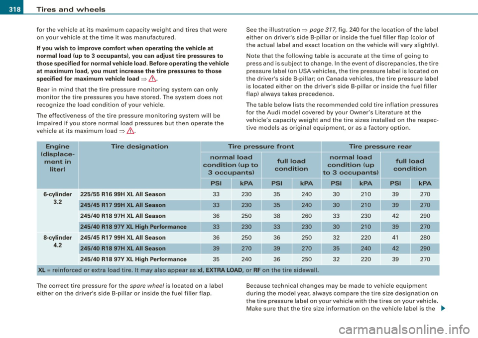
T he table below lists the recommended cold tire inflation pressures
for the Audi model covered by your Owner's Literature at the
vehic le's capacity weight and the tire sizes installed on the respec
tive models as origina l equipment, or as a factory option.
En gin e Tire des ig nation Tir e pr essur e fro nt Tir e p re ssur e rea r
( di spl ac e-
no rm al l oa d no rm al l oa d
m ent in
conditi on (up t o full lo
ad
condition (u p full lo
ad
lit er)
condition condition 3 occupants ) to 3 occ upant s)
PSI kPA kPA kPA
6-cylinder 225/5 5 R16 99H XL All Sea son 33 230 35 240
30 210
39 270
3.2
245 /45 R17 99H XL All Season 33 230 35 240 30 2 10 39 270
2 45 /40 R1 8 97 H XL All Season 36 250
38 260 33 230 42 290
245
/40 R18 97V XL Hi gh Performan ce 33 230 33 230 30 210
39 270
8
-c ylind er 245 /45 R17 99H XL All Sea son 36 250 36 250 32 220 41 280
4.2
245/40 R18 97 H XL All S eason 39 270 39 270 35 240 42 290
2
45 /40 R18 97V XL High Perf orma nce 35 240
36 250 32 220 39 270
X
L = reinforced or extra load t ire . It may also appea r as xi, EX TRA LOAD , or RF on the tire sidewall.
The correct t ire pressure for the
spare wheel is located on a label
either on the driver's side B-pillar or inside the fuel fil ler flap. Because technica
l changes may be made to vehicle equipment
during the mode l year, always compare the tire size designation on
the tire pressure label on your vehicle with the tires on your vehic le .
Make sure that the tire size information on the vehic le label is the _.,
Page 340 of 390

11111.___W_ h_ a_ t_ d_o_ l_ d_ o _ n_ o_w _ ? ____________________________________________ _
- Disengage and lower the floor panel before you close the
luggage compartment lid again.
Storing the replaced wheel
- Place the replaced wheel inside the spare wheel well in
the luggage compartment .
Tighten the knurled retaining screw clockwise to secure the wheel in place.
- Disengage and lower the floor panel before you close the
luggage compartment lid again.
& WARNING
Loose items in the passenger compartment can cause serious
personal injury during hard braking or in an accident .
• Never store the spare wheel or jack and tools in the passenger
compartment.
• Always store all jacking equipment, tools, and the spare wheel
in the luggage compartment.
• Tighten the knurled retaining screw for the spare wheel
securely.
[ i] Tips
Check the inflation pressure of the spare tire periodically to keep the
tire ready for use. •
Changing a wheel
Before changing a wheel
Observe the following precautions for your own and your
passenger's safety when changing a wheel.
- After you experience a tire failure, pull the car well away
from moving traffic and try to reach level ground before
you stop :::;. & .
- All passengers should leave the car and move to a safe
location (for instance, behind the guardrail) :::;,& .
- Engage the parking brake to prevent your vehicle from
rol ling unintentionally :::;.& .
- Move selector lever to position P :::;. & .
-If you are towing a trailer: unhitch the trailer from your
vehicle.
- Take the jack and the spare tire out of the luggage
compartment:::;.
page 336.
& WARNING
You or your passengers could be injured while changing a wheel if
you do not follow these safety precautions:
• If you have a flat tire, move a safe distance off the road. Turn off
the engine, turn the emergency flashers on and use other warning
devices to alert other motorists.
• Make sure that passengers wait
in a safe place away from the
vehicle and well away from the road and traffic.
• To help prevent the vehicle from moving suddenly and possibly
slipping off the jack, always fully set the parking brake and block
the wheel diagonally opposite the wheel being changed. When one ...
Page 341 of 390

-------------------------------------------~W~h~a~t~d~o~l ~d~o~n~o~w~ ?::__fflll
•
& WARNING (continued)
front wheel is lifted off the ground, placing the Automatic Trans
mission in "P" {Park) will
not prevent the vehicle from moving.
• Before you change a wheel, be sure the ground is level and firm.
If necessary, use a sturdy board under the jack.
• After installing the spare wheel, make sure that you replace the
flat tire/wheel in its storage area properly and tighten the knurled
retaining screw securely. •
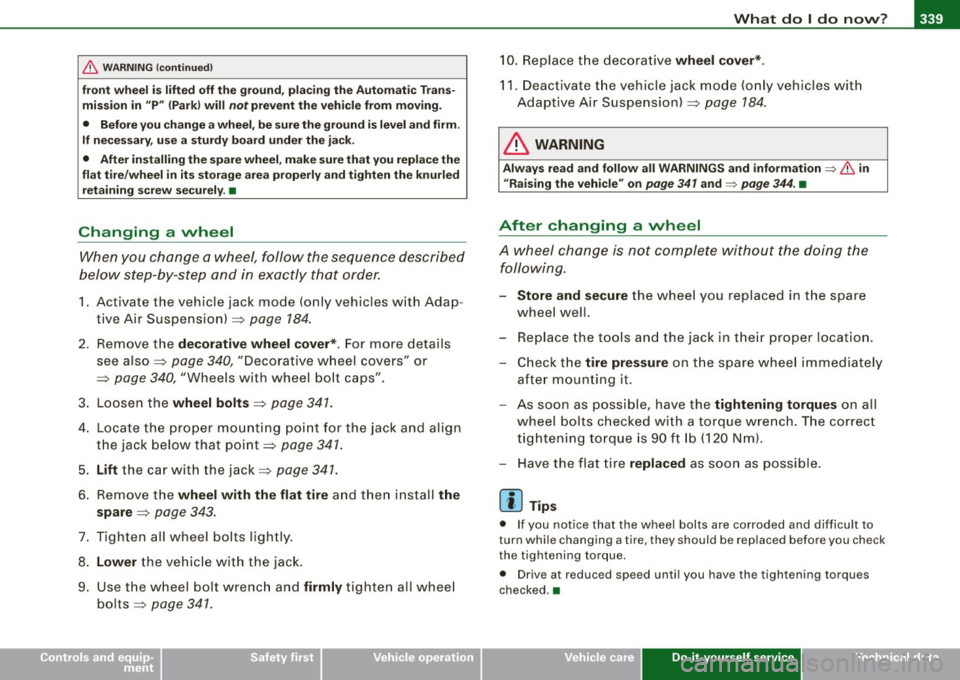
Changing a wheel
When you change a wheel, follow the sequence described
below step-by-step and in exactly that order.
1. Activate the vehicle jack mode (only vehicles with Adap
tive Air Suspension)~
page 184.
2. Remove the decorative wheel cover*. For more details
see also ~
page 340, "Decorative wheel covers" or
~ page 340, "Wheels with wheel bolt caps".
3. Loosen the
wheel bolts~ page 341.
4. Locate the proper mounting point for the jack and align
the jack below that point~
page 341.
5. Lift the car with the jack ~ page 341.
6. Remove the wheel with the flat tire and then install the
spare
~ page 343.
7. Tighten all wheel bolts lightly.
8.
Lower the vehicle with the jack.
9. Use the wheel bolt wrench and
firmly tighten all wheel
bolts~
page 341 .
10. Replace the decorative wheel cover*.
11. Deactivate the vehicle jack mode (only vehicles with
Adaptive Air Suspension)~
page 184.
& WARNING
Always read and follow all WARNINGS and information => & in
uRaising the vehicle" on
page 341 and=> page 344. •
After changing a wheel
A wheel change is not complete without the doing the
following.
- Store and secure the wheel you replaced in the spare
wheel well.
- Replace the tools and the jack in their proper location.
- Check the tire pressure on the spare wheel immediately
after mounting it.
- As soon as possible, have the
tightening torques on all
wheel bolts checked with a torque wrench. The correct
tightening torque is 90 ft lb (120 Nm).
- Have the flat tire
replaced as soon as possible.
[ i] Tips
• If you notice that the wheel bolts are corroded and difficult to
turn while changing a tire, they should be replaced before you check
the tightening torque.
• Drive at reduced speed until you have the tightening torques
checked .•
Do-it -yourself service
Page 348 of 390

llft!I Fuses and bulbs ..._ __________________________________________ _
[ i J Tip s
You are wel l advised to keep a supply of spare fuses in your vehicle .
Fuses with the proper ampere ratings are availab le at your Audi
dea ler. •
Fuse Location , Instrument Panel left
Fig . 258 Fuse pa nel
l ayo ut
Some of the equipment items listed are optional or only ava ilable on
certain model configurations .
Note th at t he fo llo wi ng t able i s acc urat e at th e time of goin g to
pr ess and is subject t o ch ang e. In th e eve nt of d iscrep ancie s, th e
labe l on th e in side of th e cover always ta kes prece de nce .
The power seats are protected by cir cuit br eaker s, which automati
cally reset after a few seconds after the overload has been reme
died.
N o. Equipm ent
1 Not used
2
3
4
Not used
Engine management
Oil level sensor Amps
5
5
No
.
5
6
..
7
8
9
10
1 1
12
13
14
15
16
17
18
19
20
21
22
23
24
25
26
27
28
Equipm ent
Climate cont rol , tire pressure monitoring sys
tem
Electronic Stabilization Program (ESP), clutch
sensor
Diagnostic connector
Homelink control unit
Automa tic dimming interior mirror
Adaptive Cruise Control
Not used
Diagnostic connector
Switch modu le steering column
Brake light switch
I nstrument c luster, control module Ga teway
Telephone, cell phone E lectronic Stabilization Program (ESP)
Headlight electronics, left -side
Rain sensor
Heated washer nozzles
Seat adjustment (driver)
MMI display
E lectromechanica l parking brake
Not used
Not used
Not used
N ot used
Not used Amps
5
5
5
5
5
5
10
10
5
10
10
10
5
5
5
10
5
5
-