Page 17 of 82
SAFETY INFORMATION
1-8
1 For Oceania and South Africa
10 3
8
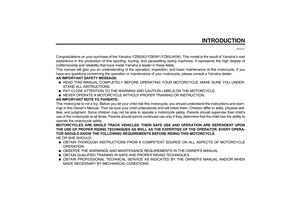
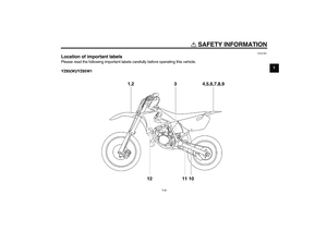
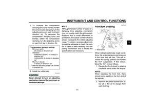
Before you operate this vehicle, read the owner’s manual.
Prima di usare il veicolo, leggete il manuale di istruzioni.
Lire le manuel du propriétaire avant d’utiliser ce véhicule.
Lesen Sie die Bedienungsanleitung bevor Sie dieses Fahrzeug fahren.
Antes de conducir este vehículo, lea el Manual del Propietario.
5PA-21568-00
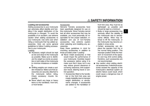
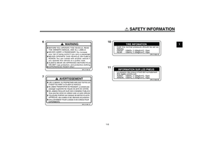
TIRE INFORMATION
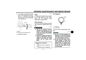
Cold tire normal pressure should be set as
follows.
FRONT : 100kPa, {
1.00kgf/cm
2}
, 15psi
REAR : 100kPa, {1.00kgf/cm2}, 15psi
3RV-21668-A0
U5PA85E0.book Page 8 Thursday, April 13, 2006 3:06 PM
Page 18 of 82
SAFETY INFORMATION
1-9
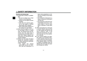
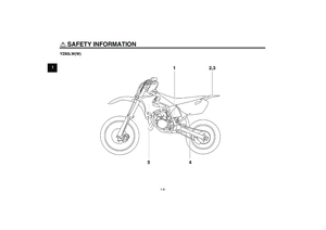
1YZ85LW(W)
U5PA85E0.book Page 9 Thursday, April 13, 2006 3:06 PM
Page 19 of 82
SAFETY INFORMATION
1-10
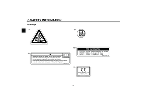
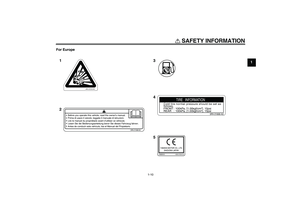
1 For Europe
3
5 4 1
2
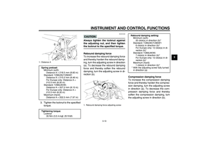
Before you operate this vehicle, read the owner’s manual.
Prima di usare il veicolo, leggete il manuale di istruzioni.
Lire le manuel du propriétaire avant d’utiliser ce véhicule.
Lesen Sie die Bedienungsanleitung bevor Sie dieses Fahrzeug fahren.
Antes de conducir este vehículo, lea el Manual del Propietario.
5PA-21568-00
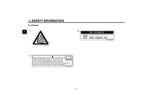
TIRE INFORMATION
Cold tire normal pressure should be set as
follows.
FRONT : 100kPa, {
1.00kgf/cm
2}
, 15psi
REAR : 100kPa, {1.00kgf/cm2}, 15psi
3RV-21668-A0
YAMAHA MOTOR CO., LTD.
SHIZUOKA JAPANYAMAHA
4GB-2155A-00
U5PA85E0.book Page 10 Thursday, April 13, 2006 3:06 PM
Page 20 of 82
SAFETY INFORMATION
1-11
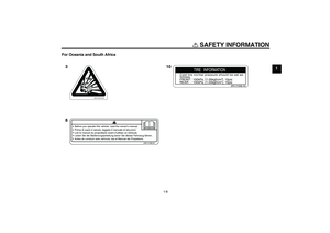
1For Oceania
4 1
2
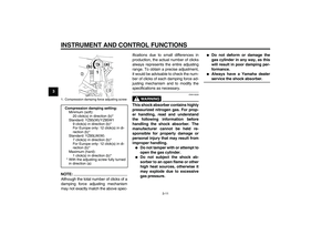
Before you operate this vehicle, read the owner’s manual.
Prima di usare il veicolo, leggete il manuale di istruzioni.
Lire le manuel du propriétaire avant d’utiliser ce véhicule.
Lesen Sie die Bedienungsanleitung bevor Sie dieses Fahrzeug fahren.
Antes de conducir este vehículo, lea el Manual del Propietario.
5PA-21568-00
TIRE INFORMATION
Cold tire normal pressure should be set as
follows.
FRONT : 100kPa, {
1.00kgf/cm
2}
, 15psi
REAR : 100kPa, {1.00kgf/cm2}, 15psi
3RV-21668-A0
U5PA85E0.book Page 11 Thursday, April 13, 2006 3:06 PM
Page 21 of 82
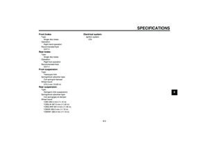
DESCRIPTION
2-1
2
EAU10410
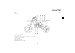
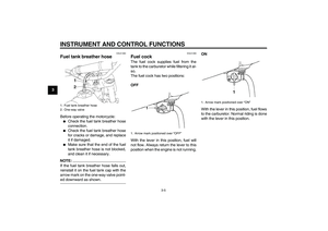
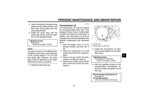
Left view1. Radiator cap (page 6-10)
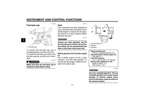
2. Fuel cock (page 3-5)
3. Shock absorber assembly spring preload adjusting nut (page 3-9)
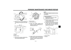
4. Air filter element (page 6-12)
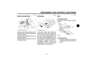
5. Seat (page 3-6)
6. Shift pedal (page 3-1)
7. Starter (choke) knob (page 3-6)
U5PA85E0.book Page 1 Thursday, April 13, 2006 3:06 PM
Page 22 of 82
DESCRIPTION
2-2
2
EAU10420
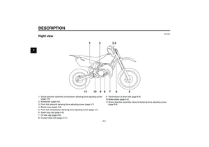
Right view1. Shock absorber assembly compression damping force adjusting screw
(page 3-9)
2. Kickstarter (page 3-6)
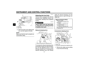
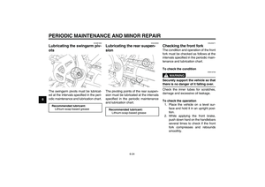
3. Front fork rebound damping force adjusting screw (page 3-7)
4. Bleed screw (page 3-8)
5. Front fork compression damping force adjusting screw (page 3-7)
6. Spark plug cap (page 6-8)
7. Oil filler cap (page 6-9)
8. Coolant drain bolt (page 6-11)9. Transmission oil drain bolt (page 6-9)
10.Brake pedal (page 3-2)
11.Shock absorber assembly rebound damping force adjusting screw
(page 3-9)U5PA85E0.book Page 2 Thursday, April 13, 2006 3:06 PM
Page 23 of 82
DESCRIPTION
2-3
2
EAU10430
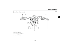
Controls and instruments1. Clutch lever (page 3-1)
2. Left handlebar switch (page 3-1)
3. Brake lever (page 3-2)
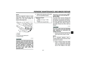
4. Throttle grip (page 6-14)
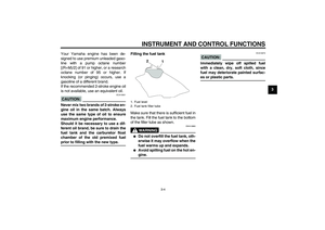
5. Fuel tank cap (page 3-3)
U5PA85E0.book Page 3 Thursday, April 13, 2006 3:06 PM
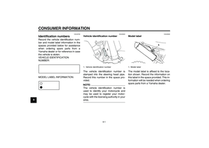
Page 24 of 82
INSTRUMENT AND CONTROL FUNCTIONS
3-1
3
EAU40660
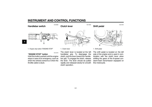
Handlebar switch
EAU12670
“ENGINE STOP” button
Hold this button pushed until the engine
stops in case of an emergency, such as
when the vehicle overturns or when the
throttle cable is stuck.
EAU12850
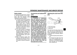
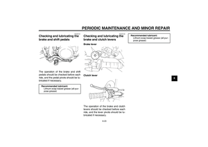
Clutch lever The clutch lever is located at the left
handlebar grip. To disengage the
clutch, pull the lever toward the handle-
bar grip. To engage the clutch, release
the lever. The lever should be pulled
rapidly and released slowly for smooth
clutch operation.
EAU12870
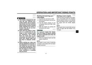
Shift pedal The shift pedal is located on the left
side of the engine and is used in com-
bination with the clutch lever when
shifting the gears of the 6-speed con-
stant-mesh transmission equipped on
this motorcycle.
1. Engine stop button “ENGINE STOP”
1. Clutch lever
1. Shift pedal
U5PA85E0.book Page 1 Thursday, April 13, 2006 3:06 PM


U5PA85E0.book Page 9 Thursday, April 13, 2006 3:06 PM")


2. Fuel cock (page 3-5)
3. Shock absorber assembly spring preload adjusting nut (page 3-9)
4. Air filter element (page 6-12)
5. Seat (pa")

2. Kickstarter (page 3-6)
3. Front fork rebound damping force adjusting screw (pag")

2. Left handlebar switch (page 3-1)
3. Brake lever (page 3-2)
4. Throttle grip (page 6-14)
5. Fuel tank cap (page 3-3)
U5P")
