Page 5 of 74

TABLE OF CONTENTESSAFETY INFORMATION .................... 1-1
DESCRIPTION ................................... 2-1Left view ........................................ 2 - 1
Right view ...................................... 2 - 2
Controls and instruments ............. 2 - 3
INSTRUMENT AND CONTROL
FUNCTIONS ....................................... 3-1 Main switch/steering lock ............. 3 - 1
Indicator and warning lights ........ 3 - 2
Speedometer ................................. 3 - 2
Tachometer .................................... 3 - 3
Multi-function display ................... 3 - 3
Handlebar switches ...................... 3 - 4
Clutch lever ................................... 3 - 5
Shift pedal ..................................... 3 - 6
Brake lever .................................... 3 - 6
Brake pedal ................................... 3 - 6
Fuel tank cap ................................. 3 - 7
Fuel ................................................ 3 - 7
Catalytic converter ........................ 3 - 8
Seat ................................................ 3 - 9
Helmet holder ................................ 3 - 9
Storage compartment .................3-10
Adjusting the shock aborber
assemblies ............................... 3-10
Luggage strap holders ...............3-11
Sidestand ..................................... 3-11
Ignition circuit cut-off system .....3-12 PRE-OPERATION CHECKS .............. 4-1
Pre-operation check list ............... 4 - 2
OPERATION AND IMPORTANT
RIDING POINTS ................................. 5-1 Starting the engine ....................... 5 - 1
Shifting ........................................... 5 - 2
Tips for reducing fuel
consumption .............................. 5 - 3
Engine break-in ............................ 5 - 3
Parking .......................................... 5 - 4
PERIODIC MAINTENANCE AND
MINOR REPAIR .................................. 6-1 Owner’s tool kit .............................. 6 - 1
Periodic maintenance and lubrication chart ......................... 6 - 2
Removing and installing the cowling and panels ................... 6 - 6
Checking the spark plug .............. 6 - 7
Engine oil and oil filter element ... 6-8
Cleaning the air filter element ... 6-11
Checking the engine idling
speed ........................................ 6-12
Checking the throttle cable free play .................................... 6-12
Valve clearance .. ........................6-12
Tires ............................................. 6-13
Cast wheels ................................. 6-15
Adjusting the clutch lever free play .................................... 6-15Adjusting the brake pedal
position and free play .............6-16
Adjusting the rear brake light switch ........................................ 6-17
Checking the front brake pads
and rear brake shoes ..............6-17
Checking the front brake fluid level .......................................... 6-18
Changing the brake fluid ...........6-18
Drive chain slack ........................6-19
Cleaning and lubricating the
drive chain ............................... 6-20
Checking and lubricating the cables ....................................... 6-21
Checking and lubricating the throttle grip and cable .............6-21
Checking and lubricating the
brake and clutch levers ...........6-21
Checking and lubricating the brake and shift pedals ............6-22
Checking and lubricating the sidestand .................................. 6-22
Lubricating the rear
suspension .............................. 6-23
Checking the front fork ...............6-23
Checking the steering ................6-24
Checking the wheel bearings ....6-24
Battery .......................................... 6-24
Replacing the fuses ....................6-26
Replacing the headlight bulb ....6-27
Replacing a turn signal light bulb or the tail/brake light bulb .......6-28
indice.pmd 24/1/2007, 14:37
1
Page 59 of 74

6-26
6
PERIODIC MAINTENANCE AND MINOR REPAIR
EAU23624
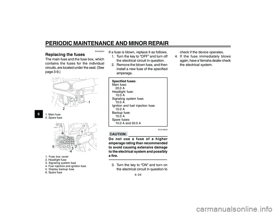
Replacing the fusesThe main fuse and the fuse box, which
contains the fuses for the individual
circuits, are located under the seat. (See
page 3-9.)
20
1
2
1. Main fuse
2. Spare fuse1. Fuse box cover
2. Headlight fuse
3. Signaling system fuse
4. Fuel injection and ignition fuse
5. Display backup fuse
6. Spare fuse
If a fuse is blown, replace it as follows.
1. Turn the key to “OFF” and turn off the electrical circuit in question.
2. Remove the blown fuse, and then install a new fuse of the specified
amperage.Specified fuses:
Main fuse:20.0 A
Headlight fuse: 10.0 A
Signaling system fuse:
10.0 A
Ignition and fuel injection fuse: 10.0 A
Backup fuse: 10.0 A
Spare fuses:
10.0 A and 20.0 A
ECA10640
Do not use a fuse of a higher
amperage rating than recommended
to avoid causing extensive damage
to the electrical system and possibly
a fire.3. Turn the key to “ON” and turn on
the electrical circuit in question to check if the device operates.
4. If the fuse immediately blows again, have a Yamaha dealer check
the electrical system.
cap 6.pmd 24/1/2007, 14:38
26
Page 72 of 74
8-3
SPECIFICATIONS
8
Headlight:Bulb type:Halogen bulbBulb voltage, wattage x quantityHeadlight: 12 V, 35 W/35.0 W x 1
Tail brake light: 12 V, 5.0 W/21.0 W x 1
Front turn signal light:
12 V, 10.0 W x 2
Rear turn signal light:
12 V, 10.0 W x 2
Position light: 12 V, 5.0 W
Meter lighting:
14 V, 2.0 W x 2
Neutral indicator light:
14 V, 1.4 W x 1
Turn signal indicator light: 14 V, 1.4 W x 2
High beam indicator light:
14 V, 1.4 W x 1
Engine trouble warning light:
LEDFuses:Main fuse:20.0 A
Headlight fuse: 10.0 A
Signaling system fuse:
10.0 A
Ignition and fuel injection fuse:
10.0 A Backup fuse:
10.0 A
Spare fuses:
10.0 A and 20.0 A
cap 8.pmd 24/1/2007, 14:38
3