Page 49 of 82
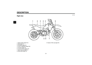
PERIODIC MAINTENANCE AND MINOR REPAIR
6-11
6
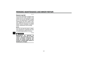
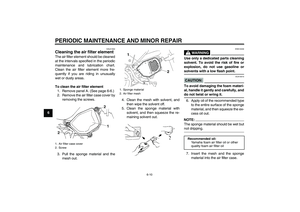
CAUTION:
ECA15571
�
Make sure that the mesh and the
sponge material are properly
seated in the air filter case.
�
The engine should never be op-
erated without the mesh and the
sponge material installed, oth-
erwise the piston(s) and/or cyl-
inder(s) may becomeexcessively worn.
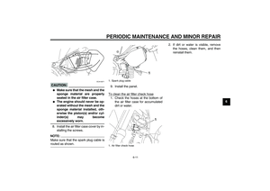
8. Install the air filter case cover by in-
stalling the screws.
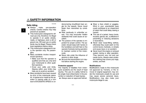
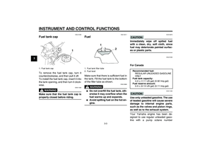
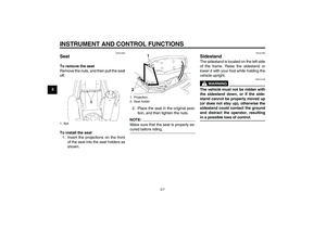
NOTE:Make sure that the spark plug cable isrouted as shown.9. Install the panel.
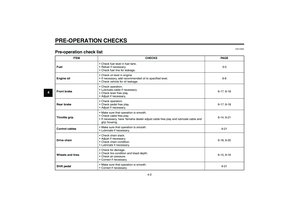
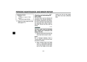
To clean the air filter check hose
1. Check the hoses at the bottom of
the air filter case for accumulated
dirt or water.2. If dirt or water is visible, remove
the hoses, clean them, and then
reinstall them.1. Spark plug cable
1. Air filter check hose
1
U3P281E0.book Page 11 Monday, April 17, 2006 11:26 AM
Page 50 of 82
PERIODIC MAINTENANCE AND MINOR REPAIR
6-12
6
EAU41230
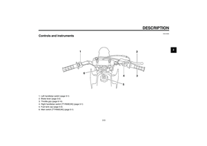
Cleaning the spark arrester The spark arrester should be cleaned
at the intervals specified in the periodic
maintenance and lubrication chart.
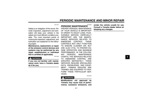
WARNING
EWA10980
�
Always let the exhaust system
cool prior to touching exhaust
components.
�
Do not start the engine whencleaning the exhaust system.
NOTE:Make sure to select a well-ventilated
area free of combustible materials toclean the spark arrester.
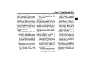
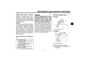
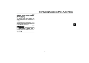
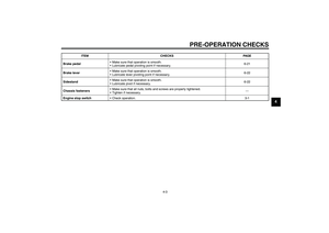
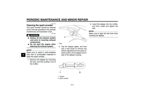
1. Remove the tailpipe by removing
the bolt, and then pulling it out of
the muffler.2. Tap the tailpipe lightly, and then
use a wire brush to remove any
carbon deposits from the spark ar-
rester portion of the tailpipe and in-
side of the tailpipe housing.3. Insert the tailpipe into the muffler,
and then install and tighten the
bolt.
NOTE:Make sure to align the bolt hole wheninserting the tailpipe.
1. Bolt
1. Tailpipe
2. Spark arrester
U3P281E0.book Page 12 Monday, April 17, 2006 11:26 AM
Page 51 of 82

PERIODIC MAINTENANCE AND MINOR REPAIR
6-13
6
EAU39930
Adjusting the carburetor The carburetor is an important part of
the engine and requires very sophisti-
cated adjustment. Therefore, most car-
buretor adjustments should be left to a
Yamaha dealer, who has the neces-
sary professional knowledge and expe-
rience. The adjustment described in the
following section, however, may be ser-
viced by the owner as part of routine
maintenance.CAUTION:
ECA10550
The carburetor has been set and ex-
tensively tested at the Yamaha fac-
tory. Changing these settings
without sufficient technical knowl-
edge may result in poor perfor-mance of or damage to the engine.
EAU21360
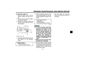
Adjusting the engine idling
speed The engine idling speed must be
checked and, if necessary, adjusted as
follows at the intervals specified in the
periodic maintenance and lubrication
chart.NOTE:
A diagnostic tachometer is needed tomake this adjustment.
1. Attach the tachometer to the spark
plug lead.
2. Start the engine and warm it up for
several minutes at 1000–2000
r/min while occasionally revving it
to 4000–5000 r/min.NOTE:The engine is warm when it quickly re-sponds to the throttle.
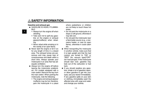
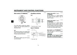
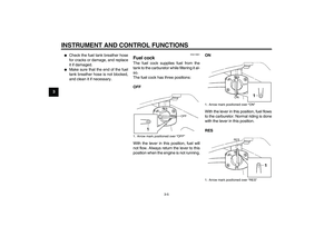
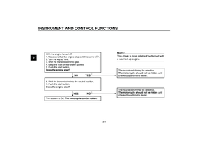
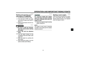
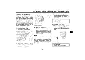
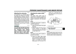
3. Check the engine idling speed
and, if necessary, adjust it to spec-
ification by turning the throttle stop
screw. To increase the engine
idling speed, turn the screw in di-rection (a). To decrease the en-
gine idling speed, turn the screw in
direction (b).
NOTE:
If the specified idling speed cannot be
obtained as described above, have aYamaha dealer make the adjustment.1. Throttle stop screw
Engine idling speed:
1400–1600 r/min
U3P281E0.book Page 13 Monday, April 17, 2006 11:26 AM
Page 52 of 82
 at the
throttle grip. Periodic")
PERIODIC MAINTENANCE AND MINOR REPAIR
6-14
6
EAU21370
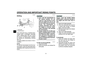
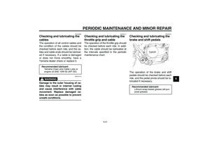
Adjusting the throttle cable
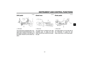
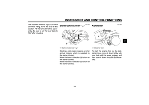
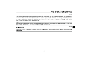
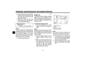
free play The throttle cable free play should mea-
sure 3.0–5.0 mm (0.12–0.20 in) at the
throttle grip. Periodically check the
throttle cable free play and, if neces-
sary, adjust it as follows.NOTE:The engine idling speed must be cor-
rectly adjusted before checking and ad-justing the throttle cable free play.
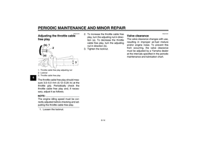
1. Loosen the locknut.2. To increase the throttle cable free
play, turn the adjusting nut in direc-
tion (a). To decrease the throttle
cable free play, turn the adjusting
nut in direction (b).
3. Tighten the locknut.
EAU21401
Valve clearance The valve clearance changes with use,
resulting in improper air-fuel mixture
and/or engine noise. To prevent this
from occurring, the valve clearance
must be adjusted by a Yamaha dealer
at the intervals specified in the periodic
maintenance and lubrication chart.
1. Throttle cable free play adjusting nut
2. Locknut
3. Throttle cable free playU3P281E0.book Page 14 Monday, April 17, 2006 11:26 AM
Page 53 of 82

PERIODIC MAINTENANCE AND MINOR REPAIR
6-15
6
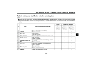
EAU39820
Tires To maximize the performance, durabil-
ity, and safe operation of your motor-
cycle, note the following points
regarding the specified tires.
Tire air pressure
The tire air pressure should be checked
and, if necessary, adjusted before each
ride.
WARNING
EWA14380
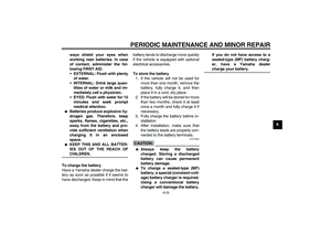
�
The tire air pressure must be
checked and adjusted on cold
tires (i.e., when the temperature
of the tires equals the ambient
temperature).
�
The tire air pressure must be ad-
justed in accordance with the
weight of the rider, the riding
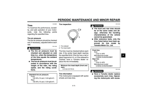
speed, and the riding condi-tions.Tire inspection
The tires must be checked before each
ride. If the center tread depth reaches
the specified limit, if the tire has a nail or
glass fragments in it, or if the sidewall is
cracked, have a Yamaha dealer re-
place the tire immediately.
Tire information
This motorcycle is equipped with spoke
wheels and tube tires.
WARNING
EWA10460
�
The front and rear tires should
be of the same make and de-
sign, otherwise the handling
characteristics of the vehicle
cannot be guaranteed.
�
After extensive tests, only the
tires listed below have been ap-
proved for this model byYamaha Motor Co., Ltd.WARNING
EWA14390
�
Have a Yamaha dealer replace
excessively worn tires. Operat-
ing the motorcycle with exces-
Standard tire air pressure:
Front:
100 kPa (15 psi) (1.00 kgf/cm²)
Rear:
100 kPa (15 psi) (1.00 kgf/cm²)
1. Tire sidewall
2. Tire tread depth
Minimum tire tread depth (front and
rear):
4.0 mm (0.16 in)
12
Front tire:
Size:
2.50-14 4PR
Manufacturer/model:
CHENG SHIN/KNOBBY
Rear tire:
Size:
3.00-12 4PR
Manufacturer/model:
CHENG SHIN/KNOBBY
U3P281E0.book Page 15 Friday, April 21, 2006 4:02 PM
Page 54 of 82

PERIODIC MAINTENANCE AND MINOR REPAIR
6-16
6sively worn tires decreases
riding stability and can lead to
loss of control.
�
The replacement of all wheel-
and brake-related parts, includ-
ing the tires, should be left to a
Yamaha dealer, who has the
necessary professional knowl-
edge and experience.
�
It is not recommended to patch
a punctured tube. If unavoid-
able, however, patch the tube
very carefully and replace it as
soon as possible with a high-quality product.
EAU21940
Spoke wheels To maximize the performance, durabil-
ity, and safe operation of your motor-
cycle, note the following points
regarding the specified wheels.�
The wheel rims should be checked
for cracks, bends or warpage, and
the spokes for looseness or dam-
age before each ride. If any dam-
age is found, have a Yamaha
dealer replace the wheel. Do not
attempt even the smallest repair to
the wheel. A deformed or cracked
wheel must be replaced.
�
The wheel should be balanced
whenever either the tire or wheel
has been changed or replaced. An
unbalanced wheel can result in
poor performance, adverse han-
dling characteristics, and a short-
ened tire life.
�
Ride at moderate speeds after
changing a tire since the tire sur-
face must first be “broken in” for it
to develop its optimal characteris-
tics.
EAU40431
Accessories and replacement
parts
WARNING
EWA14481
The accessories or replacement
parts you choose for your vehicle
should be designed specifically for
this model, and they must be se-
curely mounted to maintain the in-
herent stability of the original
design. Genuine Yamaha Parts and
Accessories are designed and test-
ed to be compatible with your vehi-
cle. Yamaha recommends the use of
Genuine Yamaha Parts and Acces-
sories before making a purchase.
Use of non-Yamaha-approved ac-
cessories or replacement parts may
cause loss of handling stability and
riding safety. Since Yamaha cannot
control the quality of accessories or
parts manufactured by other compa-
nies, Yamaha cannot be held liable
for any consequences caused by
the use of items which have notbeen approved by Yamaha.
U3P281E0.book Page 16 Monday, April 17, 2006 11:26 AM
Page 55 of 82
 as
shown. Periodically check the b")
PERIODIC MAINTENANCE AND MINOR REPAIR
6-17
6
EAU22120
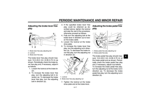
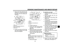
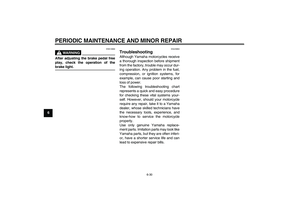
Adjusting the brake lever free
play The brake lever free play should mea-
sure 10.0–20.0 mm (0.39–0.79 in) as
shown. Periodically check the brake le-
ver free play and, if necessary, adjust it
as follows.
1. Loosen the locknut at the brake le-
ver.
2. To increase the brake lever free
play, turn the adjusting bolt in di-
rection (a). To decrease the brake
lever free play, turn the adjusting
bolt in direction (b).3. If the specified brake lever free
play could be obtained as de-
scribed above, tighten the locknut
and skip the rest of the procedure,
otherwise proceed as follows.
4. Fully turn the adjusting bolt at the
brake lever in direction (a) to loos-
en the brake cable.
5. Loosen the locknut at the brake
shoe plate.
6. To increase the brake lever free
play, turn the adjusting nut in direc-
tion (a). To decrease the brake le-
ver free play, turn the adjusting nut
in direction (b).
7. Tighten the locknut at the brake
shoe plate and at the brake lever.
EAU39811
Adjusting the brake pedal free
play The brake pedal free play should mea-
sure 10.0–20.0 mm (0.39–0.79 in) at
the brake pedal end as shown. Period-
ically check the brake pedal free play
and, if necessary, adjust it as follows.
To increase the brake pedal free play,
turn the adjusting nut at the brake rod in
direction (a). To decrease the brake
pedal free play, turn the adjusting nut in
direction (b).
1. Brake lever free play adjusting bolt
2. Locknut
3. Brake lever free play
1. Locknut
2. Brake lever free play adjusting nut
1. Brake pedal free play adjusting nut
2. Brake pedal free play
U3P281E0.book Page 17 Monday, April 17, 2006 11:26 AM
Page 56 of 82

PERIODIC MAINTENANCE AND MINOR REPAIR
6-18
6
EAU41052
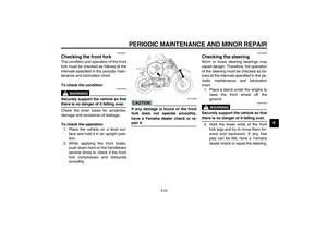
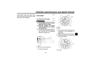
Checking the front and rear
brake shoes The front and rear brake shoes must be
checked for wear at the intervals spec-
ified in the periodic maintenance and
lubrication chart.NOTE:
The wheels must be removed to check
brake shoe lining thickness.�
To remove the front wheel: See
page 6-27.
�
To remove the rear wheel: Seepage 6-28.
FrontRear
If the lining thickness of a brake shoe is
less than 1.5 mm (0.06 in), have a
Yamaha dealer replace the brake
shoes as a set.
NOTE:Be sure to measure the brake lining atthe thinnest portion.
EAU22760
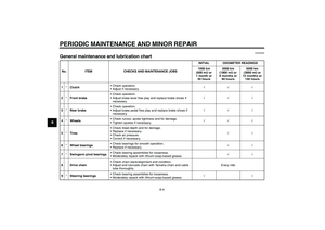
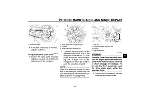
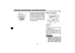
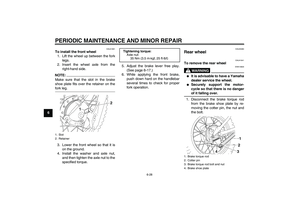
Drive chain slack The drive chain slack should be
checked before each ride and adjusted
if necessary.
EAU22771
To check the drive chain slack
1. Place the motorcycle on the side-
stand.NOTE:When checking and adjusting the drive
chain slack, there should be no weighton the motorcycle.
2. Shift the transmission into the neu-
tral position.
3. Move the rear wheel by pushing
the motorcycle to locate the tight-
est portion of the drive chain, and
then measure the drive chain slack
as shown.
1. Lining thickness
1. Lining thickness
Drive chain slack:
40.0–53.0 mm (1.57–2.09 in)
U3P281E0.book Page 18 Monday, April 17, 2006 11:26 AM