Page 25 of 90
Features and functions
18
Rear view
1Fuel tank filler cap
2Intake grate
3Speed sensor
4Stern drain plugs
5Ride plate
6Jet thrust nozzle
7Stern rope hole
8Handgrip
9Glove compartment
UF1G74E0.book Page 18 Monday, July 31, 2006 10:10 AM
Page 26 of 90
Features and functions
19
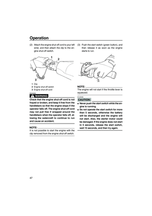
Control system
1Engine shut-off cord (lanyard)
2Engine stop switch
3Clip
4Quick Shift Trim System (QSTS) selector
5Engine shut-off switch
6Start switch
7Multifunction information center
8Throttle lever
9Oil tank filler cap
UF1G74E0.book Page 19 Monday, July 31, 2006 10:10 AM
Page 27 of 90
Features and functions
20
Engine compartment
1Spark plugs/Spark plug caps
2Electrical box
3Flushing hose connector
4Spark plug lead
5Muffler
6Fuel tank
7Oil tank
8Battery
9Fire extinguisher container
10Water separator
UF1G74E0.book Page 20 Monday, July 31, 2006 10:10 AM
Page 28 of 90
Features and functions
21
EJU31020
Operation of controls and other
functions
EJU31031Seat
There is a seat latch at the rear of the seat to
remove the seat.
To remove the seat:
Pull the seat latch up, and then pull the seat
off.
To install the seat:
Insert the projection on the front of the seat
into the stay on the deck, and then push therear of the seat down to lock it in place secure-
ly.
NOTE:
Make sure that the seat is securely installed
before operating the watercraft.
EJU31061Hood
To open the hood, push the hood latch down,
and then lift up the hood.
1Seat latch
1Hood latch
UF1G74E0.book Page 21 Monday, July 31, 2006 10:10 AM
Page 29 of 90
Features and functions
22
To close the hood, push the hood down to
lock it in place.
NOTE:
Make sure that the hood is securely closed
before operating the watercraft.
EJU31090Fuel tank filler cap
To remove the fuel tank filler cap, turn it coun-
terclockwise.
NOTE:
Make sure that the fuel tank filler cap is se-
curely closed before operating the watercraft.
EJU31100Oil tank filler cap
To remove the oil tank filler cap, turn it coun-
terclockwise.
NOTE:
Make sure that the oil tank filler cap is secure-
ly closed before operating the watercraft.
EJU31150Engine stop switch
Push the engine stop switch (red button) to
stop the engine normally.
EJU31160Engine shut-off switch
Insert the clip, on the end of the engine shut-
off cord, under the engine shut-off switch
(black button). The engine will stop automati-
cally when the clip is removed from the
1Fuel tank filler cap
1Oil tank filler cap
1Engine stop switch
UF1G74E0.book Page 22 Monday, July 31, 2006 10:10 AM
Page 30 of 90

Features and functions
23
switch, such as if the operator falls off the wa-
tercraft.
WARNING
EWJ00010
�Always attach the engine shut-off cord
to your left wrist and the clip to the en-
gine shut-off switch BEFORE starting
the engine.
�To prevent accidental starting of the en-
gine or unauthorized use by children or
others, always remove the clip from the
engine shut-off switch when the engine
is not running.
EJU31180Start switch
Push the start switch (green button) to start
the engine.
NOTE:
The engine will not start when the clip is re-
moved from the engine shut-off switch or if the
throttle lever is squeezed.
EJU31210Throttle lever
Squeeze the throttle lever to increase engine
speed.
Release the throttle lever to decrease engine
speed or to return it to the idle position.
EJU31230Cooling water pilot outlets
This watercraft is equipped with cooling water
pilot outlets.
1Clip
2Engine shut-off cord
3Engine shut-off switch
1Start switch
1Throttle lever
UF1G74E0.book Page 23 Monday, July 31, 2006 10:10 AM
Page 31 of 90

Features and functions
24
When the engine is running, cooling water is
circulated in the engine, and then it is dis-
charged from the pilot outlets.
To check for proper operation of the cooling
system, check that water is being discharged
from the pilot outlets. If water is not being dis-
charged from the outlets, cooling water may
not be circulating in the engine. When this oc-
curs, stop the engine and check for the cause.
(See pages 29 and 76 for more information.)
NOTE:
If the cooling water passages are dry, it will
take about 20 seconds for the water to reach
the outlets after the engine is started.
EJU31260Steering system
Your watercraft can be steered by turning the
handlebars in the direction you wish to travel.
When the handlebars are turned, the angle of
the jet thrust nozzle is changed, and the direc-
tion of the watercraft is changed accordingly.
Since the strength of the jet thrust determines
the speed and degree of a turn, throttle must
always be applied when attempting a turn, ex-
cept at trolling speed.
This model is equipped with the Yamaha En-
gine Management System (YEMS) that in-
cludes an off-throttle steering (OTS) system.
It will activate at planing speeds should you
attempt to steer the watercraft after releasing
the throttle lever. The OTS system assists in
turning by continuing to supply some thrust
while the watercraft is decelerating, but you
can turn more sharply if you apply throttle
while turning the handlebars.
The OTS system does not function below
planing speeds or when the engine is off.
Once the engine slows down, the watercraft
will no longer turn in response to handlebar in-
1Handlebar
2Jet thrust nozzle
UF1G74E0.book Page 24 Monday, July 31, 2006 10:10 AM
Page 32 of 90

selector
The QSTS selector is located at the left han-
dlebar grip an")
Features and functions
25
put until you apply throttle again or you reach
trolling speed.
EJU31310Quick Shift Trim System (QSTS)
selector
The QSTS selector is located at the left han-
dlebar grip and is used to adjust the trim angle
of the watercraft.
Operating the QSTS selector changes the an-
gle of the jet thrust nozzle vertically. This
changes the trim angle of the watercraft.There are 5 positions: 2 bow-down positions
(a) and (b), neutral “N”, and 2 bow-up posi-
tions (c) and (d).
To change the trim angle:
(1) Reduce engine speed to 3000 r/min or
less.
(2) Squeeze the QSTS selector lock lever,
and then turn the QSTS selector to the
desired position.
(3) Release the lock lever to lock the QSTS
selector.
CAUTION:
ECJ00010
Do not turn the QSTS selector while oper-
ating the watercraft at full throttle, other-
wise damage could occur to the QSTS.
The neutral “N” position will provide good per-
formance for most operating conditions.
1Quick Shift Trim System (QSTS) selector
2QSTS selector lock lever
UF1G74E0.book Page 25 Monday, July 31, 2006 10:10 AM


2Engine stop switch
3Clip
4Quick Shift Trim System (QSTS) selector
5Engine shut-off switch
6Start switch
7Multifunction informa")


