2007 SUZUKI SWIFT abs control module
[x] Cancel search: abs control modulePage 597 of 1496
Downloaded from www.Manualslib.com manuals search engine Electronic Stability Program: 4F-23
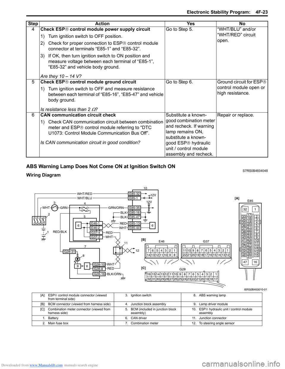
ABS Warning Lamp Does Not Come ON at Ignition Switch ONS7RS0B4604048
Wiring Diagram4
Check ESP ® control module power supply circuit
1) Turn ignition switch to OFF position.
2) Check for proper connection to ESP ® control module
connector at terminals “E85-1” and “E85-32”.
3) If OK, then turn ignition switch to ON position and measure voltage between each terminal of “E85-1”,
“E85-32” and vehicle body ground.
Are they 10 – 14 V? Go to Step 5. “WHT/BLU” and/or
“WHT/RED” circuit
open.
5 Check ESP ® control module ground circuit
1) Turn ignition switch to OFF and measure resistance between each terminal of “E85-16”, “E85-47” and vehicle
body ground.
Is resistance less than 2
Ω? Go to Step 6.
Ground circuit for ESP®
control module open or
high resistance.
6 CAN communication circuit check
1) Check CAN communication circuit between combination
meter and ESP ® control module referring to “DTC
U1073: Control Module Communication Bus Off”.
Is CAN communication circuit in good condition? Substitute a known-
good combination meter
and recheck. If warning
lamp remains ON,
substitute a known-
good ESP
® hydraulic
unit / control module
assembly and recheck. Repair or replace.
Step
Action YesNo
[A]
E85
161
15
2
3
4
5
6
7
8
9
10
11
12
13
14
17
18
19
20
21
22
23
24
25
26
27
28
29
30
31
3233
34
35
36
37
38
39
40
41
42
43
44
45
46
47
WHTGRN
3
E85-13
E85-44REDWHT6 5E46-1E46-2
4 10
6
E85-16
E85-47BLKBLK
8
9
BLK/ORN
REDWHT
REDWHT
G37-4G37-2
G28-10G28-8
G28-16
12V
12VE85-32E85-1
E85-35
WHT/REDWHT/BLU
GRN/ORN
6
2
1
7 1112[B]
G37
E46124
53
67
891011121314124
53
67
891011
1213141516171819202122
[C] G28
12345678910111213141516
17181920212223242526272829303132
G28-31
RED/BLK
I6RS0B460010-01
[A]: ESP ® control module connector (viewed
from terminal side) 3. Ignition switch 8. ABS warning lamp
[B]: BCM connector (viewed from harness side) 4. Junction block assembly 9. Lamp driver module
[C]: Combination meter connector (viewed from harness side) 5. BCM (included in junction block
assembly) 10. ESP
® hydraulic unit / control module
assembly
1. Battery 6. CAN driver11. Junction connector
2. Main fuse box 7. Combination meter12. To steering angle sensor
Page 598 of 1496
Downloaded from www.Manualslib.com manuals search engine 4F-24 Electronic Stability Program:
Circuit Description
Operation (ON/OFF) of ABS warning lamp is controlled by ESP® control module through lamp driver module in
combination meter.
If antilock brake system is in good condition, ESP ® control module turns ABS warning lamp ON at the ignition switch
ON, keeps it ON for 2 seconds and then turns it OFF. If an abnormality in the system is detected, ABS warning lamp is
turned ON continuously by ESP ® control module. Also, it is turned ON continuously by lamp driver module when the
connector of ESP ® control module is disconnected.
Troubleshooting
Refer to “Troubleshooting” under “ESP ® Warning Lamp Does Not Come ON at Ignition Switch ON”.
ABS Warning Lamp Comes ON SteadyS7RS0B4604049
Wiring Diagram
Refer to “Wiring Diagram” under “ABS Warning Lamp Does Not Come ON at Ignition Switch ON”.
Circuit Description
Refer to “Circuit Description” u nder “ABS Warning Lamp Does Not Co me ON at Ignition Switch ON”.
Troubleshooting
Refer to “Troubleshooting” under “ESP ® Warning Lamp Comes ON Steady”.
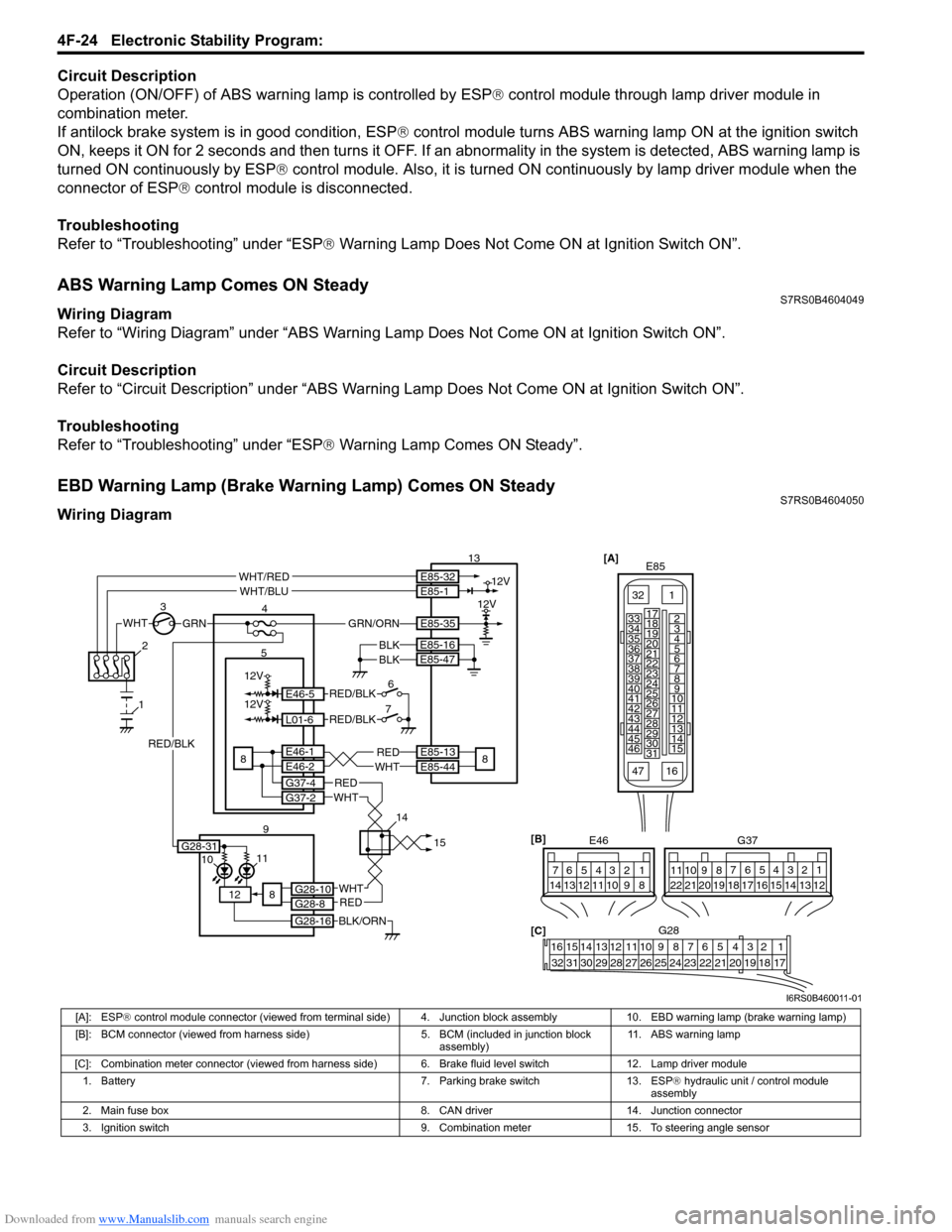
EBD Warning Lamp (Brake Warning Lamp) Comes ON SteadyS7RS0B4604050
Wiring Diagram
[A]
E85
161
15
2
3
4
5
6
7
8
9
10
11
12
13
14
17
18
19
20
21
22
23
24
25
26
27
28
29
30
31
3233
34
35
36
37
38
39
40
41
42
43
44
45
46
47WHTGRN
3
E85-13
E85-44REDWHT8 5E46-1E46-2
4
13
8
E85-16
E85-47BLKBLK
1110
12
BLK/ORN
REDWHT
REDWHT
G37-4G37-2
G28-10G28-8
G28-16
12V
12VE85-32E85-1
E85-35
WHT/REDWHT/BLU
GRN/ORN
8
2
1
9 1415
[B]
G37
E46
124
53
67
891011121314124
53
67
891011
1213141516171819202122
[C] G28
12345678910111213141516
17181920212223242526272829303132
12V
12V
6
7E46-5
L01-6
RED/BLK
RED/BLK
G28-31
RED/BLK
I6RS0B460011-01
[A]: ESP ® control module connector (viewed from terminal side) 4. Junction block assembly 10. EBD warning lamp (brake warning lamp)
[B]: BCM connector (viewed from harness side) 5. BCM (included in junction block
assembly) 11. ABS warning lamp
[C]: Combination meter connector (viewed from harness side) 6. Brake fluid level switch 12. Lamp driver module 1. Battery 7. Parking brake switch 13. ESP ® hydraulic unit / control module
assembly
2. Main fuse box 8. CAN driver 14. Junction connector
3. Ignition switch 9. Combination meter 15. To steering angle sensor
Page 599 of 1496
Downloaded from www.Manualslib.com manuals search engine Electronic Stability Program: 4F-25
Circuit Description
EBD warning lamp (brake warning lamp) is controlled by ESP® control module and BCM through lamp driver module
in combination meter.
If EBD system is in good condition, ESP ® control module turns EBD warning lamp ON at the ignition switch ON,
keeps it ON for 2 seconds and then turns it OFF.
EBD warning lamp is turned ON cont inuously at the following conditions.
• EBD system is an abnormality
• Connector of ESP ® control module is disconnected
• Parking brake switch is ON
• Brake fluid level is lower than minimum level
The information of parking brake switch and brake fluid leve l are transmitted from BCM to lamp driver module in
combination meter through CAN communication line.
Troubleshooting
Step Action Yes No 1 Check parking brake and brake fluid level
1) Make sure that:
• Parking brake is completely released.
• Brake fluid level is upper than the minimum level.
Are the check results OK? Go to Step 2. Release parking brake
completely and/or
replenish brake fluid.
2 Check ABS warning lamp
1) Turn ignition switch to ON position.
Does ABS warning lamp come on steady? Perform “ABS Warning
Lamp Does Not Come
ON at Ignition Switch
ON” previously outlined.Go to Step 3.
3 Check parking brake switch circuit and brake fluid level
switch circuit
1) Release parking brake completely, and replenish brake
fluid.
2) Disconnect BCM connectors with ignition switch turned OFF.
3) Measure resistance between each terminal of “L01-6”, “E46-5” and vehicle body ground.
Are resistance
∞ Ω? Go to Step 4. Check each applicable
circuit for short to
vehicle body ground. If
OK, then check parking
brake switch and/or
brake fluid level switch.
4 CAN communication circuit check
1) CAN communication circuit between combination meter,
ABS (ESP® ) control module and BCM referring to “DTC
U1073: Control Module Communication Bus Off”.
Is CAN communication circuit in good condition? Substitute a known-
good combination meter
and recheck. If EBD
warning lamp remains
ON, substitute a known-
good ESP
® hydraulic
unit / control module
assembly and recheck. Repair or replace.
Page 631 of 1496

Downloaded from www.Manualslib.com manuals search engine Electronic Stability Program: 4F-57
3) Remove front brake pipe referring to “Front Brake Hose / Pipe Removal and In stallation in Section 4A”.
4) Remove ESP ® hydraulic unit / control module with
bracket from vehicle by removing bracket bolts.
5) Remove bolt (4) and pull out ESP ® hydraulic unit /
control module assembly (1) from bracket (3) using
flat end rod or the like (2).
Installation 1) Install hydraulic unit / co ntrol module assembly and
by reversing removal procedure.
Tightening torque
Brake pipe flare nut: 16 N·m (1.6 kgf-m, 11.5 lb-
ft)
ESP ® hydraulic unit / control module assembly
bolt: 9 N·m (0.9 kgf-m, 6.5 lb-ft)
ESP ® hydraulic unit / control module assembly
bracket bolt: 25 N·m (2.5 kgf-m, 18.0 lb-ft)
2) Bleed air from brake system referring to “Air Bleeding of Brake System in Section 4A”.
3) Check each installed part for fluid leakage.
4) Connect SUZUKI Scan Tool.
5) Turn ignition switch to ON position. And SLIP indicator lamp flush. (Other than replace with new
one) If other than SLIP indicator lamp light, check
DTC and repair it.
6) Turn ignition switch to ON position. And ESP®
warning lamp, SLIP indicator lamp, ESP ® OFF
lamp, Brake warning lamp lights and ABS warning
lamp flush. (Replace new one)
7) Check DTC.
NOTE
If any DTC(s) other than C1075, C1076 or
C1078 are detected, sensor calibration can
not be completed. Repair the detected it(s)
first.
8) Perform “Sensor Calibration”.
9) Perform “ESP ® Hydraulic Unit Operation Check”.
10) Turn ignition switch to OFF position once and then
ON position. In this state, make sure that indicator
light and warning light turns off.
11) Check DTC(s) are not stored in hydraulic unit / control module.
Front / Rear Wheel Speed Sensor On-Vehicle
Inspection
S7RS0B4606028
CAUTION!
Incorrect voltage and/or wrong connection
cause damage to wheel speed sensor.
Output Voltage Inspection
1) Disconnect negative (–) cable from battery.
2) Hoist vehicle a little.
3) Disconnect wheel speed sensor connector.
4) Disconnect wheel speed grommet from vehicle body.
5) Set up measuring devices as shown in figure, the resistance to 115 Ω and the power supply voltage
to12 V.
4
1
2 3
I6RS0B460030-02
[A]: Front wheel speed sensor 3. “WHT” wire terminal
[B]: Rear wheel speed sensor 4. “BLK” wire terminal
1. Wheel speed sensor connector 5. Power supply (12 V)
2. Resistance (115 Ω)
V
2
5
4 1
3
43
1
[A]
[B]
I6RS0B460031-02
Page 645 of 1496
Downloaded from www.Manualslib.com manuals search engine Automatic Transmission/Transaxle: 5A-1
Transmission / Transaxle
Automatic Transmission/Transaxle
Precautions
Precautions in Diagnosing TroubleS7RS0B5100001
• Do not disconnect couplers from TCM, battery cable from battery, TCM ground wire harness from engine or
main fuse before checking the diagnostic information
(DTC, freeze frame data, etc.) stored in TCM memory.
Such disconnection will clea r memorized information
in TCM memory.
• Diagnostic information stored in TCM memory can be cleared as well as checked by using SUZUKI scan
tool or generic scan tool. Before using scan tool, read
its Operator’s (Instruction) Manual carefully to have
good understanding as to what functions are available
and how to use it.
It is indistinguishable wh ich module turns on MIL
because not only ECM but also TCM turns on MIL.
Therefore, check both ECM and TCM for DTC when
MIL lights on.
When checking TCM for DTC, keep in mind that DTC
is displayed on the scan tool as follows depending on
the scan tool used.
– SUZUKI scan tool displays DTC detected by TCM.
– Generic scan tool displays DTC detected by each of ECM and TCM simultaneously.
• Using SUZUKI scan tool the diagnostic information stored in TCM memory can be checked and cleared
as well. Before its use, be sure to read Operator’s
Manual supplied with it carefully to have good
understanding of its functions and usage.
• Be sure to read “Precautions for Electrical Circuit Service in Section 00” befo re inspection and observe
what is written there.
• TCM replacement
– When substituting a known-good TCM, check that all relays and actuators have resistance of
specified value.
Neglecting this check may result in damage to good
TCM.
• Communication of ECUs , ECM, TCM, ABS control
module, keyless start control module and BCM is
established by CAN (Controller Area Network).
Therefore, handle CAN communication line with care
referring to “Precaution for CAN Communication
System in Section 00”.
Precautions for Disassembly and ReassemblyS7RS0B5100002
When repairing automatic transaxle, it is necessary to
conduct the on-vehicle test to investigate where the
cause of the trouble lies first.
Then whether overhaul should be done or not is
determined. If the transaxle is disassembled without
such preliminary procedure, not only the cause of the
trouble would be unknown, but also a secondary trouble
may occur and often time would be wasted.
As the automatic transaxle consists of high precision
component, the following cautions should be strictly
observed when handling its parts in disassembly and
reassembly.
• Disassembling valve body assembly is prohibited
essentially. However, a few parts can be
disassembled. When disassembling valve body
component parts, confirm whether their parts are
allowed to disassemble or not referring to “Valve Body
Assembly Disassembly and Reassembly”.
• When component part of forward clutch, direct clutch, 2nd brake and/or O/D and 2nd coast brake, namely
clutch disc, brake disc, retaining plate and/or
separator plate, have been replaced, all learned
contents, which have been stored in TCM memory by
executing learning control, should be initialized
referring to “Learning Control Initialization”.
• Make sure to wash dirt off from the transaxle so that no such dirt will enter the transaxle during
dismounting and remounting.
• Select a clean place free from dust and dirt for overhauling.
• Place a rubber mat on the work bench to protect parts from damage.
• Work gloves or shop cloth should not be used. (Use a nylon cloth or a paper towel.)
• When separating the case joint, do not pry with a screwdriver or such but tap with a plastic hammer
lightly.
• Make sure to wash dirt off from the transaxle so that no such dirt will enter the transaxle during
disassembly and reassembly.
• Wash the disassembled parts in ATF (Automatic Transaxle Fluid) or kerosene (using care not to allow
ATF or kerosene to get on your face, etc.) and confirm
that each fluid passage is not clogged by blowing air
into it. But use kerosene to wash the discs, resin
washers and rubber parts.
• Replace each gasket, oil seal and O-ring with a new one.
• Apply ATF to sliding or rotating parts before
reassembly.
Page 647 of 1496
Downloaded from www.Manualslib.com manuals search engine Automatic Transmission/Transaxle: 5A-3
General Description
A/T DescriptionS7RS0B5101001
This automatic transaxle is electronic control full automatic transaxle with forward 4-speed and reverse 1-speed.
The torque converter is a 3-element, 1-step and 2-phase type and is equipped with an automatically controlled lock-up
mechanism.
The gear change device consists of a ravigneau type planet ary gear unit, 3 multiple disc type clutches, 3 multiple disc
type brakes and 2 one-way clutches.
The hydraulic pressure control device consists of a valve body assembly, pressure control solenoid valve (linear
solenoid), 2 shift solenoid va lves, TCC pressure control solenoid valve (lin ear solenoid) and a timing solenoid valve.
Optimum line pressure complying with engine torque is produced by the pressure control solenoid valve in
dependence upon control signal from transmission control module (TCM). This makes it possible to control the line
pressure with high accuracy in accordance with the engine power and running conditions to achieve smooth shifting
characteristics and high efficiency.
A clutch-to-clutch control system is prov ided for shifting between 3rd gear and 4th gear. This clutch-to-clutch control
system is made to function optimally , so that hydraulic pressure controls such as shown below are conducted.
• When upshifting from 3rd gear to 4th gear, to adjust the drain hydraulic pressure at releasing the forward clutch, a
timing solenoid valve is used to switch a hydraulic passage with an orifice to another during shifting.
• When downshifting from 4th gear to 3rd gear, to adjust the line pressure applied to the forward clutch at engaging the forward clutch, a timing solenoid valve is used to s witch a hydraulic passage with an orifice to another during
shifting.
• When upshifting from 3rd gear to 4th gear with engine throttle opened, to optimize the line pressure applied to the forward clutch at releasing the forward clutch, the learning control is processed to compensate the switching timing
of the timing solenoid at every shifting.
• When downshifting from 4th gear to 3rd gear with engine throttle opened, to optimize the line pressure applied to
the forward clutch at engaging the forw ard clutch, the learning control is processed to compensate the line pressure
at every shifting.
Employing the ravigneau type planetary gear unit and this clutch-to-clutch control system greatly simplifies the
construction to make possible a lightweight and compact transaxle.
A line pressure learning control is conducted to provide opti mum shifting time at every upshifting with engine throttle
opened. If long upshifting time is detected, the subsequent line pressure applied during upshifting is intensified. On the
contrary, if short upshifting time is detected, the subs equent line pressure applied during upshifting is weakened.
Slip controlled lock-up function
Even at a lower speed than when the TCC gets engaged completely, control over the TCC pressure control solenoid
works to cause the TCC to slip (be engaged slightly), ther eby improving the transmission efficiency. While such slip
control is being executed, the oil pressure applied to the TCC is controlled by the TCC pressure control solenoid so
that the difference between the engine speed and the input shaft speed becomes close to the specified value.
Also, during deceleration, the TCC is made to slip (be enga ged slightly) to raise the engine speed and enlarge the fuel
cut operation range so that better fuel consumption is achieved.
Due to this reason, it is absolutely necessary for the automati c transmission to use ATF suitable for slip control. Use of
any fluid other than the specified ATF may cause j uddering or some other faulty condition to occur.
Page 713 of 1496
Downloaded from www.Manualslib.com manuals search engine Automatic Transmission/Transaxle: 5A-69
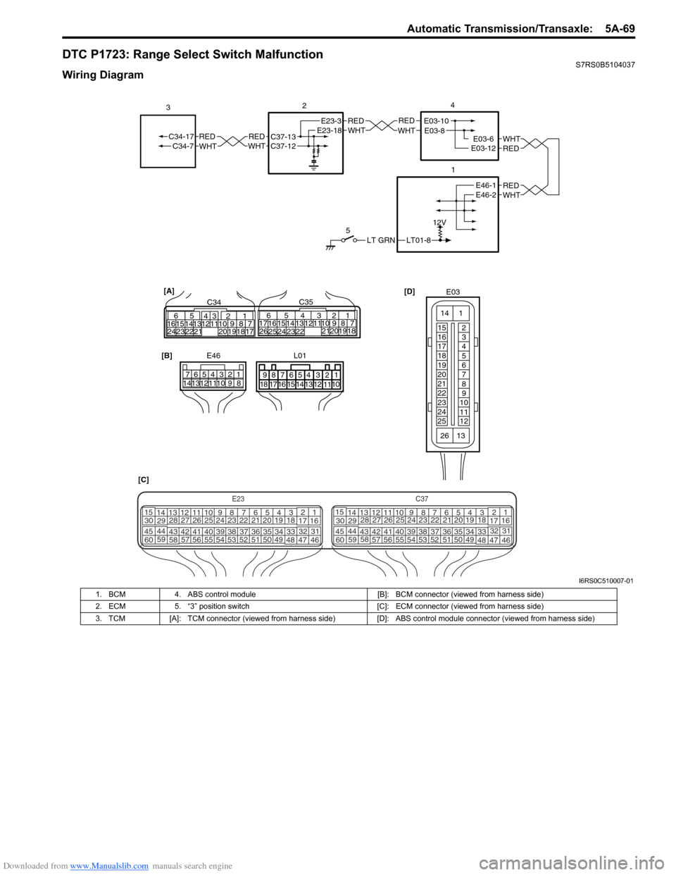
DTC P1723: Range Select Switch MalfunctionS7RS0B5104037
Wiring Diagram
LT01-8
12V
LT GRN
5
REDWHTE03-6E03-12
1
2
REDWHT
4
[D]
[C] [B]
E46
1234567
891011121314
REDWHTC37-13C37-12REDWHTC34-17C34-7
3
32
1110 9
212019 87
18
165
1615 14131211 43
2423 2122 10 9 8 7
21
1920 1817
C3417 16
26 2515 14
654
13 12
23 2224 C35
[A]
E23-3E23-18REDWHTE03-10E03-8
REDWHTE46-1E46-2
E03
15
16
17
18
19
20
21
22
23
24
25 2
3
4
5
6
7
8
9
10
11
12
1
13
14
26
E23C37
34
1819
567
1011
17
20
47 46
495051
2122
52 16
25 9
24
14
29
5557 54 53
59
60 58 2
262728
15
30
56 4832 31
34353637
4042 39 38
44
45 43 41 33 1
1213
238
34
1819
567
1011
17
20
47 46
495051
2122
52 16
25 9
24
14
29
5557 54 53
59
60 58 2
262728
15
30
56 4832 31
34353637
4042 39 38
44
45 43 41 331
1213
238
L01
678
9 54321
15161718 14 13 12 1110
I6RS0C510007-01
1. BCM
4. ABS control module [B]: BCM connector (viewed from harness side)
2. ECM 5. “3” position switch [C]: ECM connector (viewed from harness side)
3. TCM [A]: TCM connector (viewed from harness side) [D]: ABS control module connector (viewed from harness side)
Page 715 of 1496
Downloaded from www.Manualslib.com manuals search engine Automatic Transmission/Transaxle: 5A-71
DTC P1774: CAN Communication Bus OffS7RS0B5104038
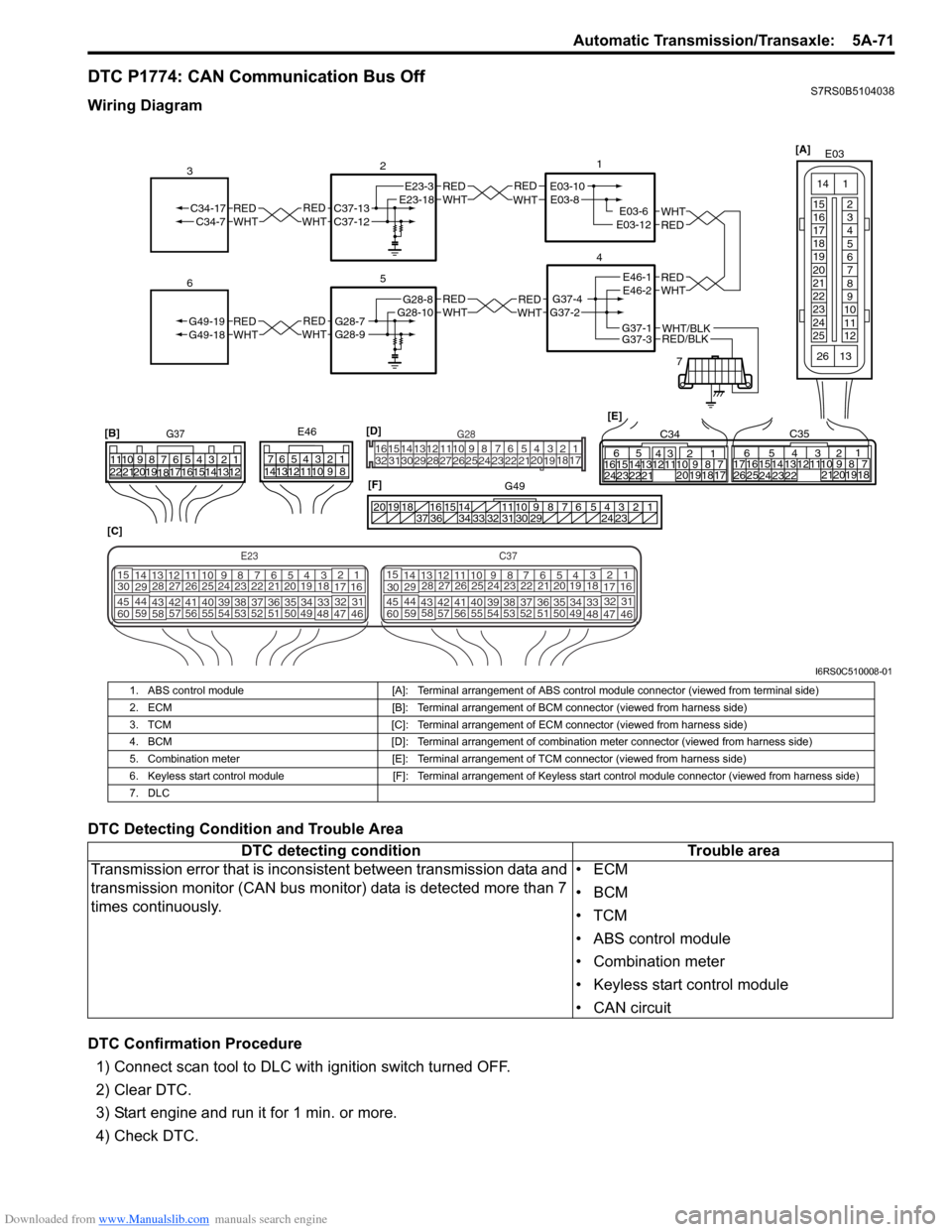
Wiring Diagram
DTC Detecting Condition and Trouble Area
DTC Confirmation Procedure1) Connect scan tool to DLC with ignition switch turned OFF.
2) Clear DTC.
3) Start engine and run it for 1 min. or more.
4) Check DTC.
REDWHTE03-6E03-12
1
4
7
REDWHT
2
[C]
[B]
G37E46
1234567
1234567
891011
891011
121314 121314
151617
18
19202122 [E]65
1615 14131211 43
2423 2122 10 9 8 7
21
1920 1817
C3417 16
26 2515 14
65 3
42
13 12
23 2224 1110 9
212019 87
18
1
C35
[F]
REDWHTC37-13C37-12REDWHTC34-17C34-7
3
1234567891011
141516
36 34 33 32 31 30 29 24 23
37
181920
[D] [A]
G49
E23-3E23-18
5
REDWHTG28-7G28-9REDWHTG49-19G49-18
6
REDWHTE03-10E03-8
G37-4G37-2
REDWHTE46-1E46-2REDWHTREDWHTG28-8G28-10
RED/BLKWHT/BLKG37-3G37-1
E03
15
16
17
18
19
20
21
22
23
24
25 2
3
4
5
6
7
8
9
10
11
12
1
13
14
26
E23C37
34
1819
567
1011
17
20
47 46
495051
2122
52 16
25 9
24
14
29
5557 54 53
59
60 58 2
262728
15
30
56 4832 31
34353637
4042 39 38
44
45 43 41 33 1
1213
238
34
1819
567
1011
17
20
47 46
495051
2122
52 16
25 9
24
14
29
5557 54 53
59
60 58 2
262728
15
30
56 4832 31
34353637
4042 39 38
44
45 43 41 331
1213
238
G281234567
8
910111213141516
1718
19
20
212223242526272829303132
I6RS0C510008-01
1. ABS control module [A]: Terminal arrangement of ABS control module connector (viewed from terminal side)
2. ECM [B]: Terminal arrangement of BCM connector (viewed from harness side)
3. TCM [C]: Terminal arrangement of ECM connector (viewed from harness side)
4. BCM [D]: Terminal arrangement of combination meter connector (viewed from harness side)
5. Combination meter [E]: Terminal arrangement of TCM connector (viewed from harness side)
6. Keyless start control module [F]: Terminal arrangement of Keyless start control module connector (viewed from harness side)
7. DLC
DTC detecting condition Trouble area
Transmission error that is incons istent between transmission data and
transmission monitor (CAN bus monitor) data is detected more than 7
times continuously. •ECM
•BCM
•TCM
• ABS control module
• Combination meter
• Keyless start control module
• CAN circuit