2007 SUZUKI SWIFT power window main switch
[x] Cancel search: power window main switchPage 1169 of 1496

Downloaded from www.Manualslib.com manuals search engine Table of Contents 9-iii
Door Switch (Front / Rear Door) Inspection ...... 9C-17
Rear End Door Switch Inspection ..................... 9C-17
Outside Air Temperature Sensor Removal and Installation (If Equipped) .......................... 9C-17
Outside Air Temperature Sensor Inspection (If Equipped) ................................................... 9C-17
Instrument Panel Removal and Installation....... 9C-18
Information Display (Clock) Removal and Installation ....................................................... 9C-19
Audio Unit Removal and In stallation ................. 9C-19
Front Speaker Removal and Installation ........... 9C-19
Rear Speaker Removal and Installation............ 9C-20
Horn Removal and Installation .......................... 9C-20
Horn Inspection ................................................. 9C-20
Horn Relay Inspection ....................................... 9C-20
Antenna Amplifier Removal and Installation ..... 9C-21
Remote Audio Control Switch Removal and Installation (If Equipped) ................................. 9C-21
Remote Audio Control Switch Inspection (If Equipped)........................................................ 9C-22
Vehicle Speed Signal Inspection (For Audio Unit) (If Equipped) ........................................... 9C-22
Specifications ..................................................... 9C-22
Tightening Torque Specifications ...................... 9C-22
Wipers / Washers............ ......................... 9D-1
Diagnostic Information and Procedures ............ 9D-1
Front Wiper and Washer Symptom Diagnosis .... 9D-1
Rear Wiper and Washer Symptom Diagnosis..... 9D-1
Repair Instructions .............................................. 9D-2 Wipers and Washers Components ..................... 9D-2
Washer Tank and Washer Pump Removal and Installation .................................................. 9D-3
Washer Pump Inspection .................................... 9D-3
Windshield Wiper Removal and Installation ........ 9D-4
Windshield Wiper Motor Inspection..................... 9D-5
Rear Wiper Removal and Installation.................. 9D-6
Rear Wiper Motor Inspection .............................. 9D-7
Windshield Wiper and Washer Switch Removal and Installation................................... 9D-7
Windshield Wiper and Washer Switch Inspection.......................................................... 9D-8
Rear Wiper and Washer Switch Removal and Installation ......................................................... 9D-9
Rear Wiper and Washer Switch Inspection......... 9D-9
Rear Wiper Relay Removal and Installation ..... 9D-10
Rear Wiper Relay Inspection ............................ 9D-10
Specifications ..................................................... 9D-10
Tightening Torque Specifications ...................... 9D-10
Glass / Windows / Mirrors.. ..................... 9E-1
General Description ............................................. 9E-1
Rear End Door Window Defogger System Description ........................................................ 9E-1
Windshield Construction ..................................... 9E-1
Diagnostic Information and Procedures ............ 9E-2 Rear End door Window Defogger Symptom Diagnosis .......................................................... 9E-2 Power Window Control System Symptom
Diagnosis .......................................................... 9E-2
Power Door Mirror Control System Symptom Diagnosis .......................................................... 9E-3
Door Mirror Heater Symptom Diagnosis (If
Equipped) .......................................................... 9E-3
Repair Instructions ........... ................................... 9E-4
Windshield Removal and In stallation .................. 9E-4
Front Door Window Components ........................ 9E-8
Front Door Glass Removal and Installation ........ 9E-8
Front Door Window Re gulator Removal and
Installation ......................................................... 9E-9
Front Door Window Regula tor Inspection ......... 9E-10
Rear Door Window Components ...................... 9E-10
Rear Door Glass Removal and Installation ....... 9E-11
Rear Door Window Regulator Removal and Installation ....................................................... 9E-12
Rear Door Window Regulato r Inspection .......... 9E-12
Rear End Door Window Components ............... 9E-13
Rear End Door Glass Removal and Installation ....................................................... 9E-13
Rear End Door Window Defogger Switch Inspection ........................................................ 9E-14
Rear End Door Window Defogger Relay Inspection ........................................................ 9E-14
Rear End Door Window Defogger Wire Inspection ........................................................ 9E-15
Rear End Door Window Defogger Wire
Repair.............................................................. 9E-15
Power Window Main Switch Inspection ............ 9E-16
Power Window Sub Switch Inspection .............. 9E-17
Door Mirror Components.. ................................. 9E-18
Door Mirror Removal and In stallation................ 9E-18
Power Door Mirror Switch Inspection ................ 9E-18
Power Door Mirror Actuator Inspection ............. 9E-19
Door Mirror Heater Switch Inspection (If Equipped) ........................................................ 9E-19
Door Mirror Heater Inspec tion (If Equipped) ..... 9E-19
Special Tools and Equipmen t ........................... 9E-19
Recommended Service Material ....................... 9E-19
Security and Locks......... ..........................9F-1
General Description ............................................. 9F-1
Key Coding Construction .................................... 9F-1
Rear End Door Opener System Description ....... 9F-1
Component Location ............ ............................... 9F-2
Power Door Lock and Keyless Entry System
Component Location ......................................... 9F-2
Diagnostic Information and Procedures ............ 9F-3 Power Door Lock System Symptom Diagnosis .......................................................... 9F-3
Power Door Lock System Operation Inspection .......................................................... 9F-3
Keyless Entry System Symptom Diagnosis (If
Equipped) .......................................................... 9F-4
Keyless Entry System Operation Inspection ....... 9F-5
Door Lock Function of Keyless Start System Symptom Diagnosis (If Equipped)..................... 9F-5
Page 1175 of 1496
![SUZUKI SWIFT 2007 2.G Service Workshop Manual Downloaded from www.Manualslib.com manuals search engine Wiring Systems: 9A-4
How to Read Connector Layout DiagramS7RS0B9101004
[A-1]: Harness symbol and corresponding harness name
A: Battery harness SUZUKI SWIFT 2007 2.G Service Workshop Manual Downloaded from www.Manualslib.com manuals search engine Wiring Systems: 9A-4
How to Read Connector Layout DiagramS7RS0B9101004
[A-1]: Harness symbol and corresponding harness name
A: Battery harness](/manual-img/20/7607/w960_7607-1174.png)
Downloaded from www.Manualslib.com manuals search engine Wiring Systems: 9A-4
How to Read Connector Layout DiagramS7RS0B9101004
[A-1]: Harness symbol and corresponding harness name
A: Battery harness
B: A/C harness
C: Engine harness
D: Injector harness
E: Main harness, Oil pressure switch wire, Console wire
G: Instrument panel harness
J: Side door wire (Power window)
K: Interior light harness, Rear speaker wire, Roof wire
L: Floor harness, G sensor wire (Fuel pump harness)
M: Rear bumper harness
O: Rear end door harness
Q: Air bag/Pretensioner harness
R: (Fuel pump wire)
[A-2]: Connector Number
[B]: Ground point No.
12
11
[B] [B]
Connector code
[A-1] [A-2]L 36
L13 L15
R01
L14
L12
L11L10
L09 L36
R02
L24
L25
L33
L28
L20 L26 (TO O01)
{
L05
L16
L32
L19
L01 (TO G01)
L02 (TO E04)
L03 (TO E05)
L42
R05
R04
L07 (TO K02)
I2RH01910901-01
Page 1192 of 1496
Downloaded from www.Manualslib.com manuals search engine 9A-21 Wiring Systems:
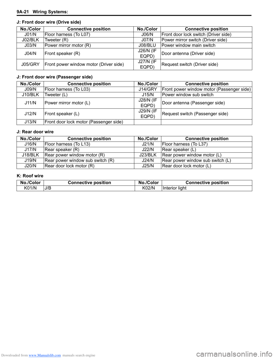
J: Front door wire (Drive side)
J: Front door wire (Passenger side)
J: Rear door wire
K: Roof wireNo./Color Connective position No.
/Color Connective position
J01/N Floor harness (To L07) J06/N Front door lock switch (Driver side)
J02/BLK Tweeter (R) J07/N Power mirror switch (Driver side) J03/N Power mirror motor (R) J08/BLU Power window main switch
J04/N Front speaker (R) J26/N (IF
EQPD) Door antenna (Driver side)
J05/GRY Front power window motor (Driver side) J27/N (IF
EQPD) Request switch (Driver side)
No./Color
Connective position No./ColorConnective position
J09/N Floor harness (To L03) J14/GRY Front power window motor (Passenger side)
J10/BLK Tweeter (L) J15/N Power window sub switch
J11/N Power mirror motor (L) J28/N (IF
EQPD) Door antenna (Passenger side)
J12/N Front speaker (L) J29/N (IF
EQPD) Request switch (Passenger side)
J13/N Front door lock motor (Passenger side)
No./Color Connective position No./ColorConnective position
J16/N Floor harness (To L13) J21/N Floor harness (To L37)
J17/N Rear speaker (R) J22/N Rear speaker (L)
J18/BLK Rear power window motor (R) J23/BLK Rear power window motor (L)
J19/N Rear power window sub switch (R) J24/N Rear power window sub switch (L)
J20/N Rear door lock motor (R) J25/N Rear door lock motor (L)
No./ColorConnective position No./Color Connective position
K01/N J/B K02/N Interior light
Page 1193 of 1496
Downloaded from www.Manualslib.com manuals search engine Wiring Systems: 9A-22
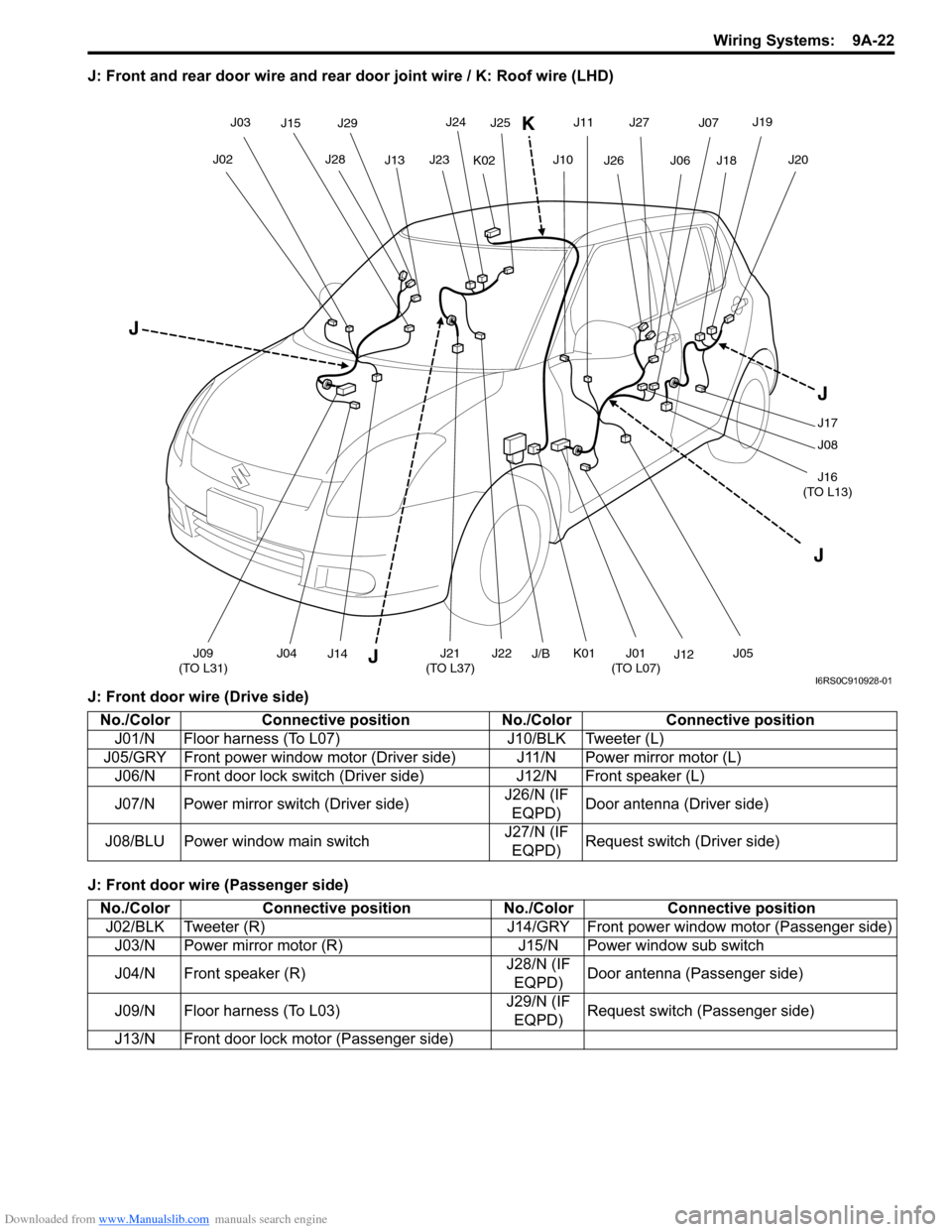
J: Front and rear door wire and rear door joint wire / K: Roof wire (LHD)
J: Front door wire (Drive side)
J: Front door wire (Passenger side)
J04J21
(TO L37)
J02
J03
J13
J15J29
J28 J25J23
J24
JJ09
(TO L31) J22J01
(TO L07)J12
J10J06J18
J19
J20
J J
J17
J08
J16
(TO L13)
J05
J11
J26
J07
J27
J14
J
K02
K
J/BK01
I6RS0C910928-01
No./Color Connective position No./Color Connective position
J01/N Floor harness (To L07) J10/BLK Tweeter (L)
J05/GRY Front power window motor (Driver side) J11/N Power mirror motor (L) J06/N Front door lock switch (Dri ver side)J12/N Front speaker (L)
J07/N Power mirror switch (Driver side) J26/N (IF
EQPD) Door antenna (Driver side)
J08/BLU Power window main switch J27/N (IF
EQPD) Request switch (Driver side)
No./Color
Connective position No./ColorConnective position
J02/BLK Tweeter (R) J14/GRY Front power window motor (Passenger side)
J03/N Power mirror motor (R) J15/N Power window sub switch
J04/N Front speaker (R) J28/N (IF
EQPD) Door antenna (Passenger side)
J09/N Floor harness (To L03) J29/N (IF
EQPD) Request switch (Passenger side)
J13/N Front door lock motor (Passenger side)
Page 1207 of 1496
Downloaded from www.Manualslib.com manuals search engine Wiring Systems: 9A-36
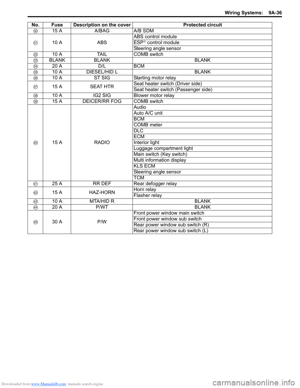
15 AA/BAG A/B SDM
10 A ABSABS control module
ESP
® control module
Steering angle sensor
10 A TAIL COMB switch
BLANK BLANK BLANK 20 A D/L BCM
10 A DIESEL/HID L BLANK
10 A ST SIG Starting motor relay
15 A SEAT HTR Seat heater switch (Driver side)
Seat heater switch (Passenger side)
10 A IG2 SIG Blower motor relay
15 A DEICER/RR FOG COMB switch
15 A RADIO Audio
Auto A/C unit
BCM
COMB meter
DLC
ECM
Interior light
Luggage compartment light
Main switch (Key switch)
Multi information display
KLS ECM
Steering angle sensor
TCM
25 A RR DEF Rear defogger relay
15 A HAZ-HORN Horn relay
Flasher relay
10 A MTA/HID R BLANK
20 A P/WT BLANK
30 A P/W Front power window main switch
Front power window sub switch
Rear power window sub switch (R)
Rear power window sub switch (L)
No. Fuse Description on the cover Protected circuit
Page 1236 of 1496
Downloaded from www.Manualslib.com manuals search engine 9A-65 Wiring Systems:
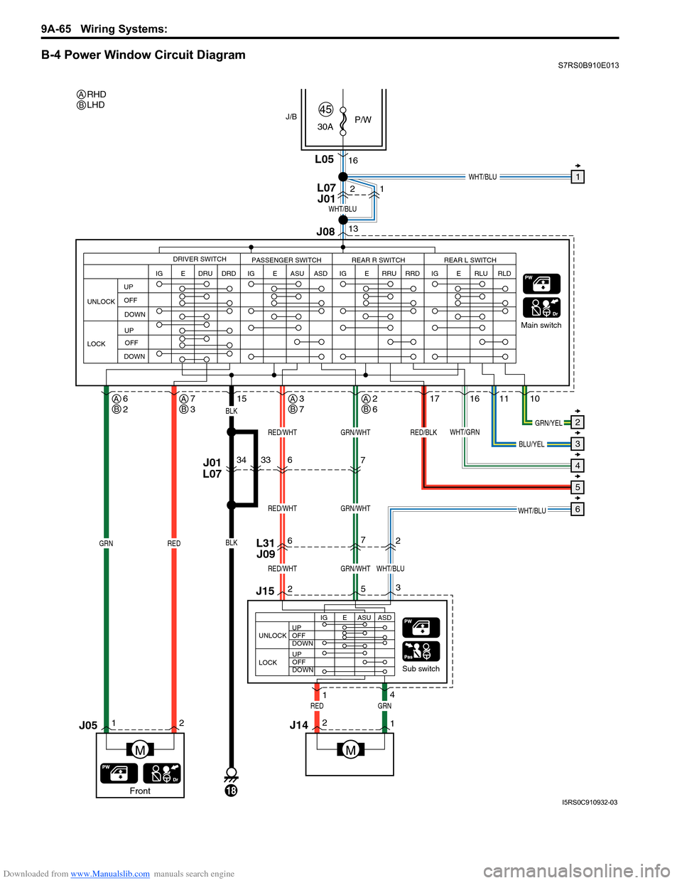
B-4 Power Window Circuit DiagramS7RS0B910E013
12
J15
L31J09
J01
L076
6
34
7
2
7
16
235
1011
1716
1
4
30A
P/W
45
Sub switch Main switch
J1421
GRNRED
RED
15
L05
J/B
18
BLK
BLK
2
13
WHT/BLU
WHT/BLU1
2
3
4
5
6
RED/WHTWHT/BLUGRN/WHT
RED/WHTGRN/WHT
RED/WHTGRN/WHTGRN/YEL
BLU/YEL
RED/BLK
M
GRN
J05
UNLOCK
LOCK
IG
DRIVER SWITCH
PASSENGER SWITCH REAR R SWITCH REAR L SWITCH
E DRU DRD
IG E ASU ASDIG E RLU RLDIG E RRU RRD
WHT/GRN
L07 J01
M
UP
OFF
DOWN
UP OFF
DOWN
J08
UNLOCK UP
OFF
DOWN
UP
OFF
DOWN
LOCK IG E ASU ASD
WHT/BLU
33
1
Front
RHD
LHD
AB
AB6
2AB7
3AB3
7AB2
6
I5RS0C910932-03
Page 1329 of 1496
Downloaded from www.Manualslib.com manuals search engine Glass / Windows / Mirrors: 9E-2
• Eyeleteer
• Piano string
• Windshield knife
• Brush for primer application (2 pcs)
•Knife
• Rubber sucker grip
• Sealant gun (for filling adhesive)
• Putty spatula (for correcting adhered parts)
Diagnostic Information and Procedures
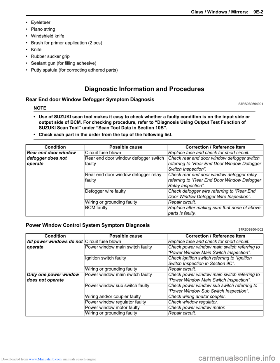
Rear End door Window Defogger Symptom DiagnosisS7RS0B9504001
NOTE
• Use of SUZUKI scan tool makes it easy to check whether a faulty condition is on the input side or
output side of BCM. For checking procedure, re fer to “Diagnosis Using Output Test Function of
SUZUKI Scan Tool” under “Scan Tool Data in Section 10B”.
• Check each part in the order from the top of the following list.
Power Window Control System Symptom DiagnosisS7RS0B9504002
Condition Possible cause Correction / Reference Item
Rear end door window
defogger does not
operate Circuit fuse blown
Replace fuse and check for short circuit.
Rear end door window defogger switch
faulty Check rear end door window defogger switch
referring to “Rear End Door Window Defogger
Switch Inspection”.
Rear end door window defogger relay
faulty Check rear end door window defogger relay
referring to “Rear End Door Window Defogger
Relay Inspection”.
Defogger wire faulty Check defogger wire referring to “Rear End
Door Window Defogger Wire Inspection”.
Wiring or grounding faulty Repair circuit.
BCM faulty Replace after making sure that none of above
parts is faulty.
ConditionPossible cause Correction / Reference Item
All power windows do not
operate Circuit fuse blown
Replace fuse and check for short circuit.
Power window main switch faulty Check power window main switch referring to
“Power Window Main Switch Inspection”.
Ignition switch faulty Check ignition switch referring to “Ignition
Switch Inspection in Section 9C”.
Wiring or grounding faulty Repair circuit.
Only one power window
does not operate Power window main switch faulty
Check power window main switch referring to
“Power Window Main Switch Inspection”.
Power window sub switch faulty Check power window sub switch referring to
“Power Window Sub Switch Inspection”.
Wiring and/or coupler faulty Check wiring and/or coupler.
Power window regulator faulty Check window regulator.
Power window motor faulty Check power window motor.
Wiring or grounding faulty Repair circuit.
Page 1343 of 1496
Downloaded from www.Manualslib.com manuals search engine Glass / Windows / Mirrors: 9E-16
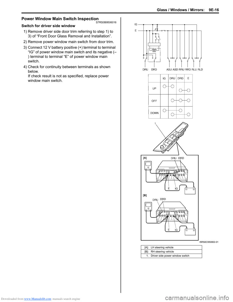
Power Window Main Switch InspectionS7RS0B9506016
Switch for driver side window 1) Remove driver side door trim referring to step 1) to 3) of “Front Door Glass Removal and Installation”.
2) Remove power window main switch from door trim.
3) Connect 12 V battery positive (+) terminal to terminal “IG” of power window main switch and its negative (–
) terminal to terminal “E” of power window main
switch.
4) Check for continuity between terminals as shown below.
If check result is not as specified, replace power
window main switch.
[A]: LH steering vehicle
[B]: RH steering vehicle
1. Driver side power window switch
I5RS0C950002-01