2007 SUZUKI SWIFT dead lock
[x] Cancel search: dead lockPage 22 of 1496
Downloaded from www.Manualslib.com manuals search engine 0A-1 General Information:
General Information
General Information
General Description
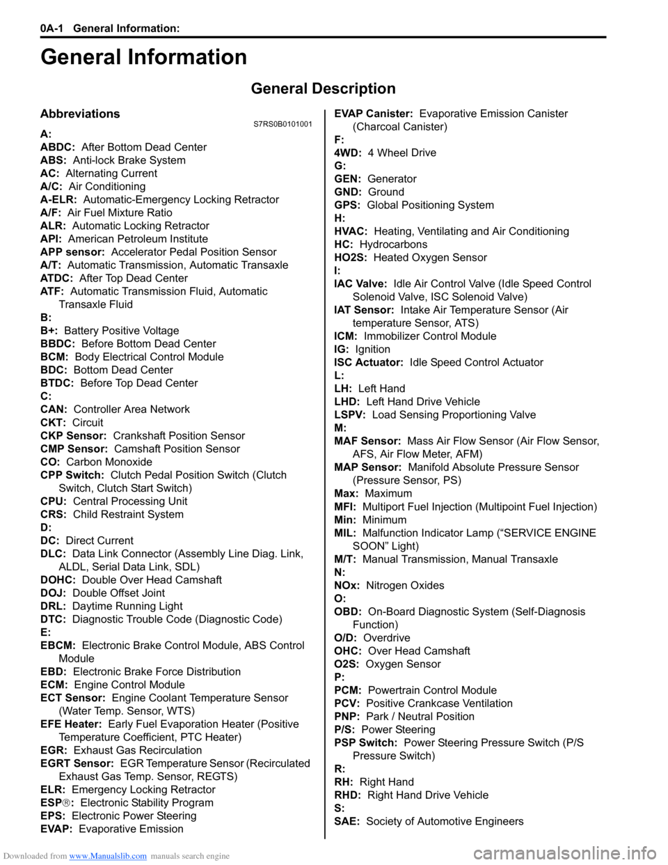
AbbreviationsS7RS0B0101001
A:
ABDC: After Bottom Dead Center
ABS: Anti-lock Brake System
AC: Alternating Current
A/C: Air Conditioning
A-ELR: Automatic-Emergency Locking Retractor
A/F: Air Fuel Mixture Ratio
ALR: Automatic Locking Retractor
API: American Petroleum Institute
APP sensor: Accelerator Pedal Position Sensor
A/T: Automatic Transmission , Automatic Transaxle
AT D C : After Top Dead Center
ATF: Automatic Transmission Fluid, Automatic
Transaxle Fluid
B:
B+: Battery Positive Voltage
BBDC: Before Bottom Dead Center
BCM: Body Electrical Control Module
BDC: Bottom Dead Center
BTDC: Before Top Dead Center
C:
CAN: Controller Area Network
CKT: Circuit
CKP Sensor: Crankshaft Position Sensor
CMP Sensor: Camshaft Position Sensor
CO: Carbon Monoxide
CPP Switch: Clutch Pedal Position Switch (Clutch
Switch, Clutch Start Switch)
CPU: Central Processing Unit
CRS: Child Restraint System
D:
DC: Direct Current
DLC: Data Link Connector (Assembly Line Diag. Link,
ALDL, Serial Data Link, SDL)
DOHC: Double Over Head Camshaft
DOJ: Double Offset Joint
DRL: Daytime Running Light
DTC: Diagnostic Trouble Code (Diagnostic Code)
E:
EBCM: Electronic Brake Cont rol Module, ABS Control
Module
EBD: Electronic Brake Force Distribution
ECM: Engine Control Module
ECT Sensor: Engine Coolant Temperature Sensor (Water Temp. Sensor, WTS)
EFE Heater: Early Fuel Evaporation Heater (Positive
Temperature Coefficient, PTC Heater)
EGR: Exhaust Gas Recirculation
EGRT Sensor: EGR Temperature Sensor (Recirculated
Exhaust Gas Temp. Sensor, REGTS)
ELR: Emergency Locking Retractor
ESP ®: Electronic Stability Program
EPS: Electronic Power Steering
EVAP: Evaporative Emission EVAP Canister:
Evaporative Emission Canister
(Charcoal Canister)
F:
4WD: 4 Wheel
Drive
G:
GEN: Generator
GND: Ground
GPS: Global Positioning System
H:
HVAC: Heating, Ventilating and Air Conditioning
HC: Hydrocarbons
HO2S: Heated Oxygen Sensor
I:
IAC Valve: Idle Air Control Valve (Idle Speed Control
Solenoid Valve, ISC Solenoid Valve)
IAT Sensor: Intake Air Temperature Sensor (Air
temperature Sensor, ATS)
ICM: Immobilizer Control Module
IG: Ignition
ISC Actuator: Idle Speed Control Actuator
L:
LH: Left Hand
LHD: Left Hand Drive Vehicle
LSPV: Load Sensing Proportioning Valve
M:
MAF Sensor: Mass Air Flow Sensor (Air Flow Sensor, AFS, Air Flow Meter, AFM)
MAP Sensor: Manifold Absolute Pressure Sensor
(Pressure Sensor, PS)
Max: Maximum
MFI: Multiport Fuel Injection (Mu ltipoint Fuel Injection)
Min: Minimum
MIL: Malfunction Indicator Lamp (“SERVICE ENGINE
SOON” Light)
M/T: Manual Transmission, Manual Transaxle
N:
NOx: Nitrogen Oxides
O:
OBD: On-Board Diagnostic System (Self-Diagnosis
Function)
O/D: Overdrive
OHC: Over Head Camshaft
O2S: Oxygen Sensor
P:
PCM: Powertrain Control Module
PCV: Positive Crankcase Ventilation
PNP: Park / Neutral Position
P/S: Power Steering
PSP Switch: Power Steering Pressure Switch (P/S
Pressure Switch)
R:
RH: Right Hand
RHD: Right Hand Drive Vehicle
S:
SAE: Society of Automotive Engineers
Page 23 of 1496
Downloaded from www.Manualslib.com manuals search engine General Information: 0A-2
SAS: Steering Angle Sensor
SDM: Sensing and Diagnostic Module (Air Bag Controller, Air bag Control Module)
SDT: Smart Diagnostic Tester
SFI: Sequential Multipor t Fuel Injection
SOHC: Single Over Head Camshaft
T:
TBI: Throttle Body Fuel Injection (Single-Point Fuel
Injection, SPI)
TCC: Torque Converter Clutch
TCM: Transmission Control Module (A/T Controller, A/T
Control Module)
TDC: Top Dead Center
TP Sensor: Throttle Position Sensor TVV:
Thermal Vacuum Valve (Thermal Vacuum
Switching Valve, TVSV, Bi metal Vacuum Switching
Valve, BVSV)
TWC: Three Way Catalytic Converter (Three Way
Catalyst)
2WD: 2 Wheel Drive
U:
USB: Universal Serial Bus
V:
VIN: Vehicle Identification Number
VSS: Vehicle Speed Sensor
VVT: Variable Valve Timing (Camshaft Position Control)
W:
WU-OC: Warm Up Oxidation Catalytic Converter
WU-TWC: Warm Up Three Way Catalytic Converter
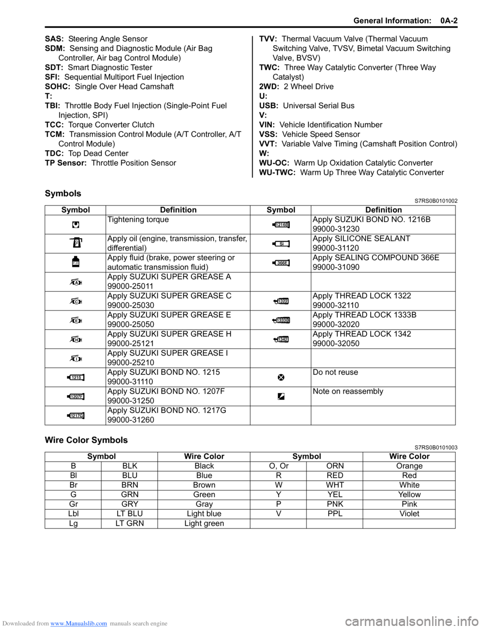
SymbolsS7RS0B0101002
Wire Color SymbolsS7RS0B0101003
Symbol Definition SymbolDefinition
Tightening torque Apply SUZUKI BOND NO. 1216B
99000-31230
Apply oil (engine, transmission, transfer,
differential) Apply SILICONE SEALANT
99000-31120
Apply fluid (brake, power steering or
automatic transmission fluid) Apply SEALING COMPOUND 366E
99000-31090
Apply SUZUKI SUPER GREASE A
99000-25011
Apply SUZUKI SUPER GREASE C
99000-25030 Apply THREAD LOCK 1322
99000-32110
Apply SUZUKI SUPER GREASE E
99000-25050 Apply THREAD LOCK 1333B
99000-32020
Apply SUZUKI SUPER GREASE H
99000-25121 Apply THREAD LOCK 1342
99000-32050
Apply SUZUKI SUPER GREASE I
99000-25210
Apply SUZUKI BOND NO. 1215
99000-31110 Do not reuse
Apply SUZUKI BO ND NO. 1207F
99000-31250 Note on reassembly
Apply SUZUKI BO ND NO. 1217G
99000-31260
Symbol Wire Color SymbolWire Color
B BLK Black O, Or ORN Orange
Bl BLU Blue RRED Red
Br BRN Brown WWHT White
G GRN Green YYEL Yellow
Gr GRY Gray PPNK Pink
Lbl LT BLU Light blueVPPL Violet
Lg LT GRN Light green
Page 1350 of 1496
Downloaded from www.Manualslib.com manuals search engine 9F-4 Security and Locks:
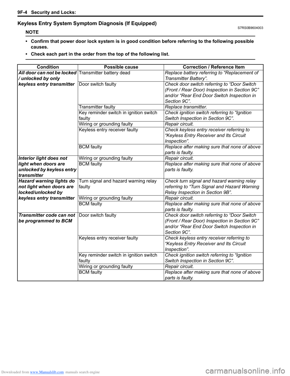
Keyless Entry System Symptom Diagnosis (If Equipped)S7RS0B9604003
NOTE
• Confirm that power door lock system is in good condition before referring to the following possible causes.
• Check each part in the order from the top of the following list.
Condition Possible cause Correction / Reference Item
All door can not be locked
/ unlocked by only
keyless entry transmitter Transmitter battery dead
Replace battery referring to “Replacement of
Transmitter Battery”.
Door switch faulty Check door switch referring to “Door Switch
(Front / Rear Door) Inspection in Section 9C”
and/or “Rear End Door Switch Inspection in
Section 9C”.
Transmitter faulty Replace transmitter.
Key reminder switch in ignition switch
faulty Check ignition switch referring to “Ignition
Switch Inspection in Section 9C”.
Wiring or grounding faulty Repair circuit.
Keyless entry receiver faulty Check keyless entry receiver referring to
“Keyless Entry Receiver and Its Circuit
Inspection”.
BCM faulty Replace after making sure that none of above
parts is faulty.
Interior light does not
light when doors are
unlocked by keyless entry
transmitter Wiring or grounding faulty
Repair circuit.
BCM faulty Replace after making sure that none of above
parts is faulty.
Hazard warning lights do
not light when doors are
locked/unlocked by
keyless entry transmitter Turn signal and hazard warning relay
faulty
Check turn signal and hazard warning relay
referring to “Turn Signal and Hazard Warning
Relay Inspection in Section 9B”.
Wiring or grounding faulty Repair circuit.
BCM faulty Replace after making sure that none of above
parts is faulty.
Transmitter code can not
be programmed to BCM Door switch faulty
Check door switch referring to “Door Switch
(Front / Rear Door) Inspection in Section 9C”
and/or “Rear End Door Switch Inspection in
Section 9C”.
Keyless entry receiver faulty Check keyless entry receiver referring to
“Keyless Entry Receiver and Its Circuit
Inspection”.
Key reminder switch in ignition switch
faulty Check ignition switch referring to “Ignition
Switch Inspection in Section 9C”.
Wiring or grounding faulty Repair circuit.
BCM faulty Replace after making sure that none of above
parts is faulty.
Page 1474 of 1496
Downloaded from www.Manualslib.com manuals search engine 10E-12 Keyless Start System:
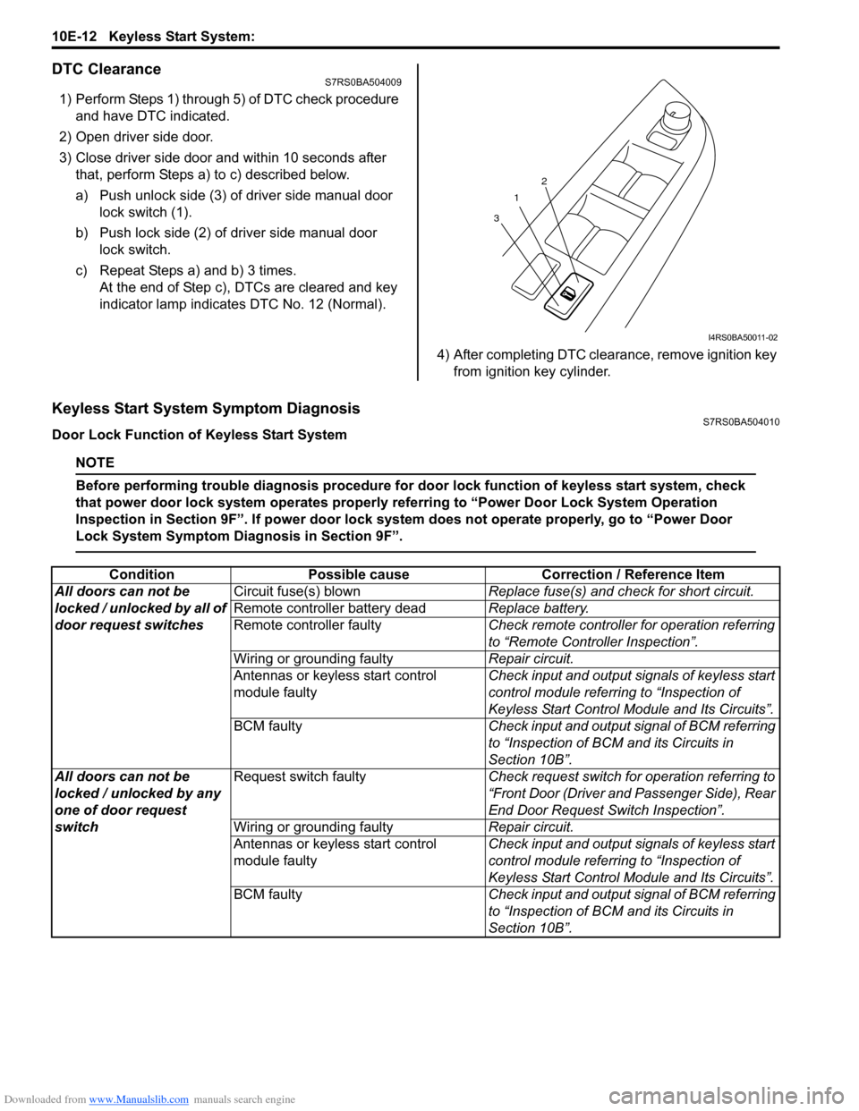
DTC ClearanceS7RS0BA504009
1) Perform Steps 1) through 5) of DTC check procedure and have DTC indicated.
2) Open driver side door.
3) Close driver side door and within 10 seconds after that, perform Steps a) to c) described below.
a) Push unlock side (3) of driver side manual door lock switch (1).
b) Push lock side (2) of driver side manual door lock switch.
c) Repeat Steps a) and b) 3 times. At the end of Step c), DTCs are cleared and key
indicator lamp indicates DTC No. 12 (Normal).
4) After completing DTC clearance, remove ignition key from ignition key cylinder.
Keyless Start System Symptom DiagnosisS7RS0BA504010
Door Lock Function of Keyless Start System
NOTE
Before performing trouble diagnosis procedure for door lock function of keyless start system, check
that power door lock system operates properly referring to “Power Door Lock System Operation
Inspection in Section 9F”. If power door lock system does not operate properly, go to “Power Door
Lock System Symptom Diagnosis in Section 9F”.
1
3 2
I4RS0BA50011-02
Condition
Possible cause Correction / Reference Item
All doors can not be
locked / unlocked by all of
door request switches Circuit fuse(s) blown
Replace fuse(s) and check for short circuit.
Remote controller battery dead Replace battery.
Remote controller faulty Check remote controller for operation referring
to “Remote Controller Inspection”.
Wiring or grounding faulty Repair circuit.
Antennas or keyless start control
module faulty Check input and output signals of keyless start
control module referring to “Inspection of
Keyless Start Control Mo
dule and Its Circuits”.
BCM faulty Check input and output signal of BCM referring
to “Inspection of BCM and its Circuits in
Section 10B”.
All doors can not be
locked / unlocked by any
one of door request
switch Request switch faulty
Check request switch for operation referring to
“Front Door (Driver and Passenger Side), Rear
End Door Request Switch Inspection”.
Wiring or grounding faulty Repair circuit.
Antennas or keyless start control
module faulty Check input and output signals of keyless start
control module referring to “Inspection of
Keyless Start Control Mo
dule and Its Circuits”.
BCM faulty Check input and output signal of BCM referring
to “Inspection of BCM and its Circuits in
Section 10B”.
Page 1475 of 1496
Downloaded from www.Manualslib.com manuals search engine Keyless Start System: 10E-13
Keyless Engine Start Function
NOTE
Before performing symptom diagnosis procedure for keyless engine start system, check that engine
starts by using ignition key. If it cannot be started by using ignition key, go to “Engine Symptom
Diagnosis in Section 1A”.
Keyless Start System Operation InspectionS7RS0BA504011
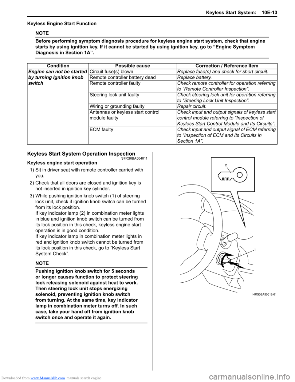
Keyless engine start operation
1) Sit in driver seat with re mote controller carried with
you.
2) Check that all doors are closed and ignition key is not inserted in ignition key cylinder.
3) While pushing ignition knob switch (1) of steering lock unit, check if ignition knob switch can be turned
from its lock position.
If key indicator lamp (2) in combination meter lights
in blue and ignition knob switch can be turned from
its lock position in this check, keyless engine start
operation is in good condition.
If key indicator lamp in combination meter lights in
red and ignition knob switch cannot be turned from
its lock position in this check, go to “Keyless Start
System Check”.
NOTE
Pushing ignition knob switch for 5 seconds
or longer causes function to protect steering
lock releasing solenoid against heat to work.
Then steering lock unit stops energizing
solenoid, preventing ignition knob switch
from turning. At the same time, key indicator
lamp in combination mete r turns off. In such
case, take your hand off from ignition knob
switch once and operate it again.
Condition Possible cause Correction / Reference Item
Engine can not be started
by turning Ignition knob
switch Circuit fuse(s) blown
Replace fuse(s) and check for short circuit.
Remote controller battery dead Replace battery.
Remote controller faulty Check remote controller for operation referring
to “Remote Controller Inspection”.
Steering lock unit faulty Check steering lock unit for operation referring
to “Steering Lock Unit Inspection”.
Wiring or grounding faulty Repair circuit.
Antennas or keyless start control
module faulty Check input and output signals of keyless start
control module referring to “Inspection of
Keyless Start Control Mo
dule and Its Circuits”.
ECM faulty Check input and output signal of ECM referring
to “Inspection of ECM and Its Circuits in
Section 1A”.
1
2
I4RS0BA50012-01