2007 SUZUKI SWIFT abs control module
[x] Cancel search: abs control modulePage 717 of 1496

Downloaded from www.Manualslib.com manuals search engine Automatic Transmission/Transaxle: 5A-73
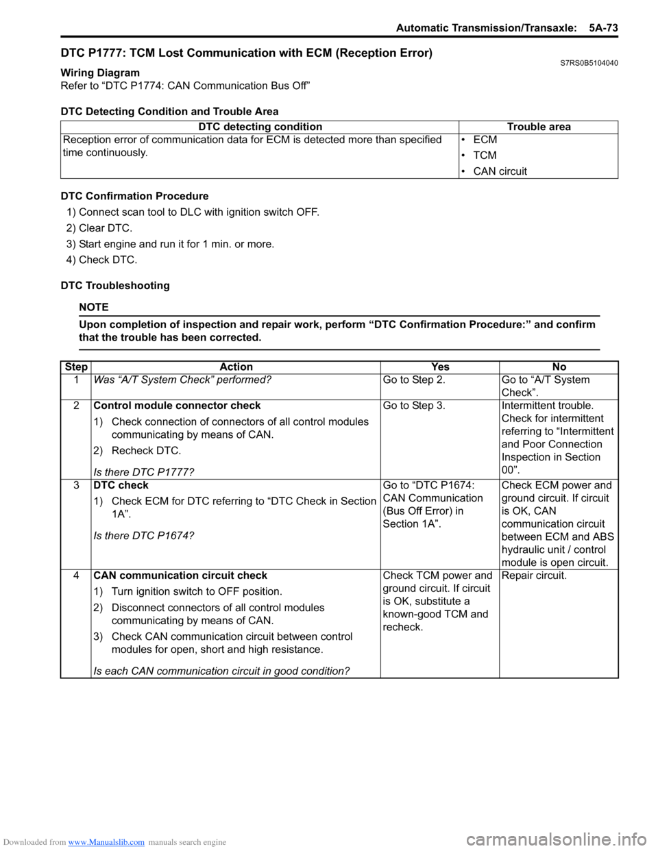
DTC P1777: TCM Lost Communication with ECM (Reception Error)S7RS0B5104040
Wiring Diagram
Refer to “DTC P1774: CAN Communication Bus Off”
DTC Detecting Condition and Trouble Area
DTC Confirmation Procedure1) Connect scan tool to DLC with ignition switch OFF.
2) Clear DTC.
3) Start engine and run it for 1 min. or more.
4) Check DTC.
DTC Troubleshooting
NOTE
Upon completion of inspection and repair work, perform “DTC Confirmation Procedure:” and confirm
that the trouble has been corrected.
DTC detecting condition Trouble area
Reception error of communication data fo r ECM is detected more than specified
time continuously. •ECM
•TCM
• CAN circuit
Step
Action YesNo
1 Was “A/T System Check” performed? Go to Step 2.Go to “A/T System
Check”.
2 Control module connector check
1) Check connection of connectors of all control modules
communicating by means of CAN.
2) Recheck DTC.
Is there DTC P1777? Go to Step 3.
Intermittent trouble.
Check for intermittent
referring to “Intermittent
and Poor Connection
Inspection in Section
00”.
3 DTC check
1) Check ECM for DTC referring to “DTC Check in Section
1A”.
Is there DTC P1674? Go to “DTC P1674:
CAN Communication
(Bus Off Error) in
Section 1A”.
Check ECM power and
ground circuit. If circuit
is OK, CAN
communication circuit
between ECM and ABS
hydraulic unit / control
module is open circuit.
4 CAN communication circuit check
1) Turn ignition switch to OFF position.
2) Disconnect connectors of all control modules
communicating by means of CAN.
3) Check CAN communication circuit between control modules for open, short and high resistance.
Is each CAN communication circuit in good condition? Check TCM power and
ground circuit. If circuit
is OK, substitute a
known-good TCM and
recheck.
Repair circuit.
Page 718 of 1496

Downloaded from www.Manualslib.com manuals search engine 5A-74 Automatic Transmission/Transaxle:
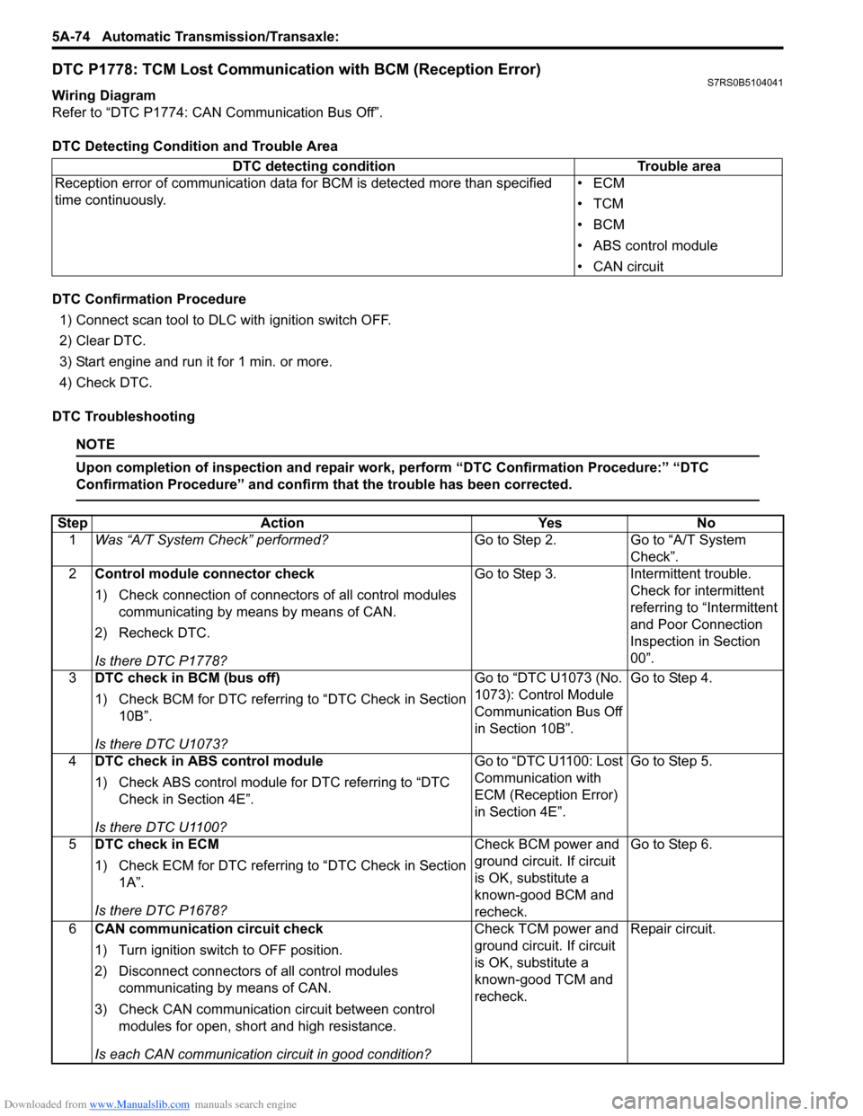
DTC P1778: TCM Lost Communication with BCM (Reception Error)S7RS0B5104041
Wiring Diagram
Refer to “DTC P1774: CAN Communication Bus Off”.
DTC Detecting Condition and Trouble Area
DTC Confirmation Procedure
1) Connect scan tool to DLC with ignition switch OFF.
2) Clear DTC.
3) Start engine and run it for 1 min. or more.
4) Check DTC.
DTC Troubleshooting
NOTE
Upon completion of inspection and repair work, perform “DTC Confirmation Procedure:” “DTC
Confirmation Procedure” and confirm that the trouble has been corrected.
DTC detecting condition Trouble area
Reception error of communication data fo r BCM is detected more than specified
time continuously. •ECM
•TCM
•BCM
• ABS control module
• CAN circuit
Step
Action YesNo
1 Was “A/T System Check” performed? Go to Step 2.Go to “A/T System
Check”.
2 Control module connector check
1) Check connection of connectors of all control modules
communicating by means by means of CAN.
2) Recheck DTC.
Is there DTC P1778? Go to Step 3.
Intermittent trouble.
Check for intermittent
referring to “Intermittent
and Poor Connection
Inspection in Section
00”.
3 DTC check in BCM (bus off)
1) Check BCM for DTC referring to “DTC Check in Section
10B”.
Is there DTC U1073? Go to “DTC U1073 (No.
1073): Control Module
Communication Bus Off
in Section 10B”.
Go to Step 4.
4 DTC check in ABS control module
1) Check ABS control module for DTC referring to “DTC
Check in Section 4E”.
Is there DTC U1100? Go to “DTC U1100: Lost
Communication with
ECM (Reception Error)
in Section 4E”.
Go to Step 5.
5 DTC check in ECM
1) Check ECM for DTC referring to “DTC Check in Section
1A”.
Is there DTC P1678? Check BCM power and
ground circuit. If circuit
is OK, substitute a
known-good BCM and
recheck.Go to Step 6.
6 CAN communication circuit check
1) Turn ignition switch to OFF position.
2) Disconnect connectors of all control modules
communicating by means of CAN.
3) Check CAN communication circuit between control modules for open, short and high resistance.
Is each CAN communication circuit in good condition? Check TCM power and
ground circuit. If circuit
is OK, substitute a
known-good TCM and
recheck.
Repair circuit.
Page 884 of 1496

Downloaded from www.Manualslib.com manuals search engine 6C-2 Power Assisted Steering System:
General Description
P/S System DescriptionS7RS0B6301001
This power steering (P/S) system consists of a P/S control module (3), a torque sensor (4), a motor (5). In this system,
the P/S control module determines the level and direction of the assist force for the steering wheel (1) according to the
signals from the torque sensor and vehicle speed signal from ECM. The P/S control module runs the motor so as to
assist the operation of the steering wheel.
The P/S control module diagnoses troubles which may occur in the area including the following components when the
ignition switch is ON and the engine is running. When the P/S control module detects any malfunction, it stops the
motor operation.
• Torque sensor
• Vehicle speed signal
• Engine speed signal
• P/S motor
• P/S control module.
2. Steering column 7. Battery9. ABS/ESP® control module
6. Steering gear case assembly 8. ECM10. Wheel speed sensor (right-front, left-front)
7
3
9
10
10
1
2
4
5
6
8
I7RS0B630001-01
Page 886 of 1496

Downloaded from www.Manualslib.com manuals search engine 6C-4 Power Assisted Steering System:
Schematic and Routing Diagram
EPS System Wiring Circuit DiagramS7RS0B6302001
M
5V
BRNRED/
BLU
BLK
RED
WHT
BLU
GRN
BRN YEL
E52-11
E52-14E52-12
E23-4
E23-26
E23-25 E51-1
E51-2
E52-18
E53-5
E53-7
E52-6
E52-8
E53-2
E52-9
E52-16
E52-19
GRY
PPL/WHT
[A ]
[E ]
12 3
4 5 67
89
11
10
12 13
141516
17 18 19 20
1
2
[B ][C ]
1210 9 8 7654 3 21
16 15 14 13 12 11
26 25 24 2322 21 20 19 18 17
32 31 30 29 28 27
[D]
5V
PPL
E52-4
11
12
13 14
15
10
9
16
12V
5V
5V
12V
REDE52-20E53-6
E53-4
E53-1
7654321
5
REDRED/
BLKWHT
6WHTWHT/BLKWHTBLK
12V
12V
17BLK
GRY
LT GRN
/BLK
E52-1
E52-5
E49-1
GRNGRNWHTBLK
WHY
G28-25G28-31
RED/BLK
18
3
4
4
7 8
4
4
1 2
4
E49-2BLK
I7RS0B630002-01
[A]: Connector “E52” (viewed from harness side) 4. Fuse 12. P/S motor
[B]: Connector “E49” (viewed from harness side ) 5. Left-front wheel speed sensor 13. Shield
[C]: Connector “E51” (viewed from harness side) 6 . Right-front wheel speed sensor 14. Torque sensor
[D]: Connector “G28” (viewed from harness side) 7. Combination meter 15. Torque sensor amplifier
[E]: Connector “E53” (viewed from harness side) 8. “EPS” warning light16. To ECM, BCM, Air bag SDM and ABS control module assembly
1. Main fuse box 9. Date link connector (DLC) 17. ABS/ESP ® control module
2. Ignition switch 10. ECM18. Individual circuit fuse box No.1
3. Junction block assembly 11. P/S control module
Page 892 of 1496

Downloaded from www.Manualslib.com manuals search engine 6C-10 Power Assisted Steering System:
�) C1121 No vehicle speed signal
(60 seconds or more) Vehicle speed signal is 0 km/h
even though engine speed is
more than 4000 rpm for more than
60 seconds continuously (before
elapse of 5 min from engine start)
or vehicle speed signal is 0 km/h
even though engine speed is
more than 2500 rpm for more than
60 seconds continuously (after
elapse of 5 min for engine start). • Vehicle speed signal circuit
• Wheel speed sensor
•ECM
• P/S control module
• ABS control module
• CAN communication circuit
Not
applicable
�) C1122 Engine speed signal Engine speed signal is less than
220 rpm for more than 0.8
seconds.
or
Engine speed signal is less than
220 rpm for more than 20
seconds continuously even
though vehicle speed signal is
more than 50 km/h.• Engine speed signal circuit
•ECM
• P/S control module
• Vehicle speed signal
1 driving
cycle
�) C1123 No vehicle speed signal
(30 seconds or more) Vehicle speed signal is 0 km/h
with continuously more than 3
driving cycles even though engine
speed is more than 4000 rpm for
more than 30 seconds
continuously (before elapse of 5
min from engine start).
or
vehicle speed signal is 0 km/h
with continuously more than 3
driving cycles even though engine
speed is more than 2500 rpm for
more than 30 seconds
continuously (after elapse of 5 min
for engine start). • Vehicle speed signal circuit
• Wheel speed sensor
•ECM
• P/S control module
• ABS control module
• CAN communication circuit
3 driving
cycles
�) C1124 Vehicle speed performance
(Impossible deceleration) Vehicle speed signal is less than 5
km/h for more
than 5 seconds
continuously with more than
specified deceleration speed (–20
m/s
2) from over 20 km/h. Not
applicable
�) C1141 P/S motor circuit voltage Voltage between both motor drive
circuits is more than 8.5 V or less
than 0.2 V for 0.5 seconds
continuously while motor is not
drived.
• P/S motor circuit
• P/S motor
• P/S control module1 driving
cycle
�) C1142 P/S motor circuit range /
performance Measured motor drive current is
more than 10 A as compared with
target motor drive current. 1 driving
cycle
DTC No. Detecting item
Detecting condition
(DTC will set when detecting) Trouble area MIL
Page 895 of 1496

Downloaded from www.Manualslib.com manuals search engine Power Assisted Steering System: 6C-13
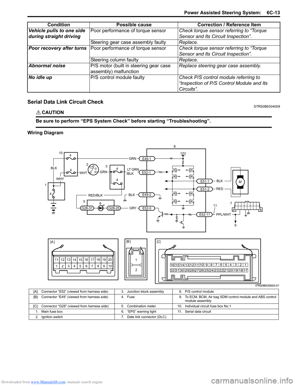
Serial Data Link Circuit CheckS7RS0B6304009
CAUTION!
Be sure to perform “EPS System Check” before starting “Troubleshooting”.
Wiring DiagramVehicle pulls to one side
during straight driving
Poor performance of torque sensor
Check torque sensor referring to “Torque
Sensor and Its Circuit Inspection”.
Steering gear case assembly faulty Replace.
Poor recovery after turns Poor performance of torque sensor Check torque sensor referring to “Torque
Sensor and Its Circuit Inspection”.
Steering column faulty Replace.
Abnormal noise P/S motor (built in steering gear case
assembly) malfunction Replace steering gear case assembly.
No idle up P/S control module faulty Check P/S control module referring to
“Inspection of P/S Control Module and Its
Circuits”.
Condition Possible cause Correction / Reference Item
MBLK
RED
E52-11 E51-1
E51-2PPL/WHT
[A ]
12
3
4 5 67
89
11
10
12 13
141516
17 18 19 2010 9 8 7654 3 21
16 15 14 13 12 11
26 25 24 2322 21 20 19 18 17
32 31 30 29 28 27
[C]
8
79
12V
[B ]
11
12
GRY
LT GRN
/BLK
E52-1
E52-5
E49-1
GRNGRNWHTBLK
WHY
G28-25G28-31
RED/BLK
10
3
4
4
5 6
4
4
1 2
4
E49-2BLK
I7RS0B630003-01
[A]: Connector “E52” (viewed from harness side) 3. Junction block assembly 8. P/S control module
[B]: Connector “E49” (viewed from harness side) 4. Fuse 9. T o ECM, BCM, Air bag SDM control module and ABS control
module assembly
[C]: Connector “G28” (viewed from harness side) 5. Comb ination meter 10. Individual circuit fuse box No.1
1. Main fuse box 6. “EPS” warning light 11. Serial data circuit
2. Ignition switch 7. Date link connector (DLC)
Page 896 of 1496

Downloaded from www.Manualslib.com manuals search engine 6C-14 Power Assisted Steering System:
TroubleshootingStep Action Yes No 1 Was “EPS System Check” performed? Go to Step 2. Go to “EPS System
Check”.
2 1) Make sure that SUZUKI scan tool is free from malfunction and that correct program card (software) for
P/S system is used.
2) Turn ignition switch to OFF position.
3) Check proper connection of SUZUKI scan tool to DLC.
Is connection in good condition? Go to Step 3. Connect SUZUKI scan
tool to DLC properly.
3 1) Check if communication is possible by making communication with other controllers (ECM, BCM, ABS
or SDM) or other vehicles.
Is it possible to communic ate with the other controllers? Go to Step 4. Repair open in common
section of “serial data
circuit” (“PPL/WHT” wire
circuit) used by all
controllers or short to
ground or power circuit
which has occurred
somewhere in serial
data circuit (“PPL/WHT”
wire circuit).
4 1) Check power supply circuit and ground circuit for P/S control module referring to “P/S Control Module Power
Supply and Ground Circuit Check”.
Is check result in good condition? Go to Step 5. Repair or replace
defective circuit.
5 1) With ignition switch turned OFF, disconnect “E52” connector from P/S control module and check for
terminal to P/S control module connector.
2) If connections are OK, check t hat “Serial data circuit” is
as following.
• Insulation resistance of “Serial data circuit” wire is infinity between its terminal and other terminals at P/S
control module connector.
• Wiring resistance of “Seria l data circuit” wire is less
than 1 Ω.
• Insulation resistance of “Serial data circuit” wire is infinity between its terminal and vehicle body ground.
Is circuit in good condition? Substitute a known-
good P/S control
module and recheck.
Repair or replace
defective circuit.
Page 908 of 1496

Downloaded from www.Manualslib.com manuals search engine 6C-26 Power Assisted Steering System:
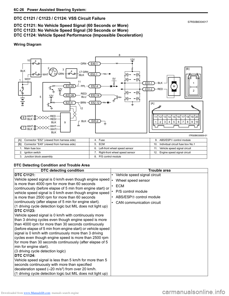
DTC C1121 / C1123 / C1124: VSS Circuit FailureS7RS0B6304017
DTC C1121: No Vehicle Speed Signal (60 Seconds or More)
DTC C1123: No Vehicle Speed Signal (30 Seconds or More)
DTC C1124: Vehicle Speed Performance (Impossible Deceleration)
Wiring Diagram
DTC Detecting Condition and Trouble Area
M
BRNRED/
BLU
BLK
RED
E52-14
E52-12
E23-4
E23-26
E23-25 E51-1
E51-2
[A ]
12
3
4 5 67
89
11
10
12 13
141516
17 18 19 20
5V
PPL
E52-4
8
5
12V
E49-2BLK
12V
12V
6REDRED/ BLKWHT
7WHTWHT/BLKWHTBLK BLK
111
2
[B ]
9
LT GRN
/BLKE52-1 E49-1
GRNGRNWHTBLK
WHY
10
3
4
4
4
4
1 2
12
I7RS0B630009-01
[A]: Connector “E52” (viewed from harness side)
4. Fuse9. ABS/ESP® control module
[B]: Connector “E49” (viewed from harness si de)5. ECM 10. Individual circuit fuse box No.1
1. Main fuse box 6. Left-front wheel speed sensor11. Vehicle speed signal circuit
2. Ignition switch 7. Right-front wheel speed sensor 12. Engine speed signal circuit
3. Junction block assembly 8. P/S control module
DTC detecting condition Trouble area
DTC C1121:
Vehicle speed signal is 0 km/h even though engine speed
is more than 4000 rpm for more than 60 seconds
continuously (before elapse of 5 min from engine start) or
vehicle speed signal is 0 km/h even though engine speed
is more than 2500 rpm for more than 60 seconds
continuously (after elapse of 5 min for engine start).
(1 driving cycle detection logic but MIL does not light up)
DTC C1123:
Vehicle speed signal is 0 km/h with continuously more
than 3 driving cycles even though engine speed is more
than 4000 rpm for more than 30 seconds continuously
(before elapse of 5 min from engine start) or vehicle speed
signal is 0 km/h with continuously more than 3 driving
cycles even though engine speed is more than 2500 rpm
for more than 30 seconds continuously (after elapse of 5
min for engine start).
(3 driving cycle detection logic)
DTC C1124:
Vehicle speed signal is less than 5 km/h for more than 5
seconds continuously with more than specified
deceleration speed (–20 m/s
2) from over 20 km/h.
(1 driving cycle detection logic but MIL does not light up) • Vehicle speed signal circuit
• Wheel speed sensor
•ECM
• P/S control module
• ABS/ESP®
control module
• CAN communication circuit