2007 SUZUKI SWIFT back-up light
[x] Cancel search: back-up lightPage 55 of 1496

Downloaded from www.Manualslib.com manuals search engine Engine General Information and Diagnosis: 1A-5
Freeze frame data clearance:
The freeze frame data is cleared at the same time as
clearance of DTC.
Non-Euro-OBD
ECM diagnosis troubles which may occur in the area
including the following parts w hen the ignition switch is
ON and the engine is running, and indicates the result by
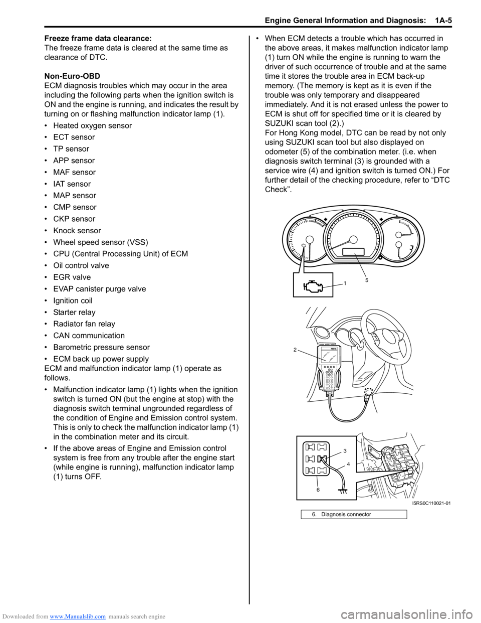
turning on or flashing malfunction indicator lamp (1).
• Heated oxygen sensor
• ECT sensor
•TP sensor
• APP sensor
• MAF sensor
• IAT sensor
• MAP sensor
• CMP sensor
• CKP sensor
• Knock sensor
• Wheel speed sensor (VSS)
• CPU (Central Processing Unit) of ECM
• Oil control valve
• EGR valve
• EVAP canister purge valve
• Ignition coil
• Starter relay
• Radiator fan relay
• CAN communication
• Barometric pressure sensor
• ECM back up power supply
ECM and malfunction indicator lamp (1) operate as
follows.
• Malfunction indicator lamp (1) lights when the ignition switch is turned ON (but t he engine at stop) with the
diagnosis switch terminal ungrounded regardless of
the condition of Engine and Emission control system.
This is only to check the ma lfunction indicator lamp (1)
in the combination meter and its circuit.
• If the above areas of Engine and Emission control system is free from any trouble after the engine start
(while engine is running), malfunction indicator lamp
(1) turns OFF. • When ECM detects a trouble which has occurred in
the above areas, it makes malfunction indicator lamp
(1) turn ON while the engi ne is running to warn the
driver of such occurrence of trouble and at the same
time it stores the trouble area in ECM back-up
memory. (The memory is kept as it is even if the
trouble was only temporary and disappeared
immediately. And it is not erased unless the power to
ECM is shut off for specified time or it is cleared by
SUZUKI scan tool (2).)
For Hong Kong model, DTC can be read by not only
using SUZUKI scan tool but also displayed on
odometer (5) of the combination meter. (i.e. when
diagnosis switch terminal (3) is grounded with a
service wire (4) and ignition switch is turned ON.) For
further detail of the checking procedure, refer to “DTC
Check”.
6. Diagnosis connector
2
1
6 3
5
4
I5RS0C110021-01
Page 739 of 1496

Downloaded from www.Manualslib.com manuals search engine Automatic Transmission/Transaxle: 5A-95
5) Shift select lever to “N” position.
NOTE
If select lever is in “P” position, shift select
lever referring to “Select Lever Inspection”.
6) Install cable casing cap (3) to selector bracket (4).
7) Connect cable end (1) to interlock cam (2) with ignition switch turned to ACC position.
8) Drive lock button (5) in cable end until it locks cable expansion and contraction.
9) With select lever set at “P ” position, turn ignition key
to ACC position and then check for the following
conditions.
• With knob button released, ignition key can be turned from ACC position to LOCK position.
• With knob button pressed, ignition key cannot be
turned from ACC position to LOCK position.
10) Install steering column cover. 11) If the vehicle is equipped with air bag system, connect negative cable at battery and enable air bag
system, referring to “Enabling Air Bag System in
Section 8B”.
Transmission Range Sensor (Shift Switch)
Inspection and Adjustment
S7RS0B5106015
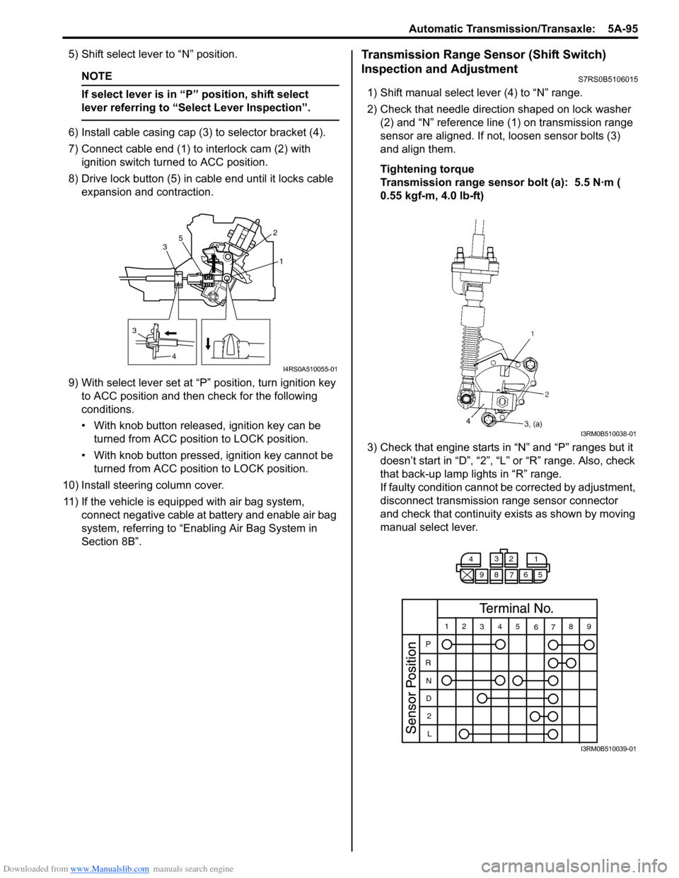
1) Shift manual select lever (4) to “N” range.
2) Check that needle direction shaped on lock washer (2) and “N” reference line (1) on transmission range
sensor are aligned. If not, loosen sensor bolts (3)
and align them.
Tightening torque
Transmission range sensor bolt (a): 5.5 N·m (
0.55 kgf-m, 4.0 lb-ft)
3) Check that engine starts in “N” and “P” ranges but it doesn’t start in “D”, “2”, “L” or “R” range. Also, check
that back-up lamp lights in “R” range.
If faulty condition cannot be corrected by adjustment,
disconnect transmission range sensor connector
and check that continuity ex ists as shown by moving
manual select lever.
3
4 1
2
3 5
I4RS0A510055-01
I3RM0B510038-01
4
3
2
1
98 76 5
12 345
6789
P
R N
D 2
L
I3RM0B510039-01
Page 992 of 1496

Downloaded from www.Manualslib.com manuals search engine 7B-44 Air Conditioning System: Automatic Type
3) Light over sunload sensor vertically with an incandescent lamp approximately 100 W apart from
about 100 mm (3.94 in.).
NOTE
If sunload sensor is not lighted over with an
incandescent lamp, DTC B1504 is detected
as current DTC even though there is not any
malfunction.
4) Turn ignition switch to ON position.
5) Erase DTC according to instructions displayed on SUZUKI scan tool.
NOTE
To know how to use SUZUKI scan tool, refer
to operator’s manual for SUZUKI scan tool.
6) After completing the clearance, turn ignition switch to OFF position, and then di sconnect SUZUKI scan
tool from DLC.
Not Using SUZUKI Scan Tool 1) Turn ignition switch to ON position.
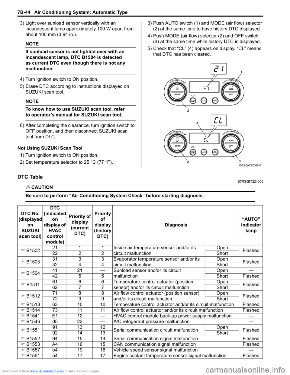
2) Set temperature selector to 25 °C (77 °F). 3) Push AUTO switch (1) and
MODE (air flow) selector
(2) at the same time to have history DTC displayed.
4) Push MODE (air flow) selector (2) and OFF switch (3) at the same time while history DTC is displayed.
5) Check that “CL” (4) appears on display. “CL” means that DTC has been cleared.
DTC TableS7RS0B7224005
CAUTION!
Be sure to perform “Air Conditioning Sy stem Check” before starting diagnosis.
1
2
3
2
4
I5RS0A722008-01
DTC No.
(displayed on
SUZUKI
scan tool) DTC
(indicated on
display of HVAC
control
module) Priority of
display
(current DTC) Priority
of
display
(history DTC) Diagnosis
“AUTO”
indicator lamp
�) B1502 21 1 1 Inside air temperature sensor and/or its
circuit malfunction Open
Flashed
22 2 2 Short
�) B1503 31 3 3 Evaporator temperature sensor and/or its
circuit malfunction Open
Flashed
32 4 4 Short
�) B1504 41 21 — Sunload sensor and/or its circuit
malfunction Open —
42 5 5 Short Flashed
�) B1511 61 6 6 Temperature control actuator (position
sensor) and/or its circuit malfunction Open
Flashed
62 7 7 Short
�) B1512 71 8 8 Air flow control actuator (position sensor)
and/or its circuit malfunction Open
Flashed
72 9 9 Short
�) B1513 63 10 10 Temperature control actuator and/or its circuit malfunction Flashed
�) B1514 73 11 11 Air flow control actuator and/or its circuit malfunction Flashed
�) B1541 E1 12 — HVAC control module back-up power supply malfunction —
�) B1546 d5 22 — A/C refrigerant pressure malfunction —
�) B1551 91 13 12
Serial communication circuit malfunction Open
Flashed
92 14 13 Short
�) B1552 94 15 14 Serial communication signal malfunction Flashed
�) B1553 A4 16 15 CAN communication signal malfunction Flashed
�) B1557 b4 19 16 Vehicle speed sensor signal malfunction —
�) B1561 54 17 17 Engine coolant temperature sensor signal malfunction Flashed
Page 1167 of 1496

Downloaded from www.Manualslib.com manuals search engine Table of Contents 9- i
9
Section 9
CONTENTS
Body, Cab and Accessories
Precautions ................................................. 9-1
Precautions............................................................. 9-1
Precautions on Body, Cab and Accessories ......... 9-1
Precautions for Body Service ................................ 9-1
Fastener Caution for Body Service ....................... 9-1
Wiring Systems............... ......................... 9A-1
Precautions........................................................... 9A-1
Cautions in Body Electrical System Servicing..... 9A-1
General Description ............................................. 9A-1 Abbreviations ...................................................... 9A-1
Wire / Connector Color Sy mbols ......................... 9A-1
Symbols and Marks ............................................ 9A-2
How to Read Connector Layout Diagram ........... 9A-4
How to Read Connector Codes and Terminal Nos.................................................................... 9A-5
How to Read Ground Point ................................. 9A-7
How to Read Power Supply Diagram.................. 9A-8
How to Read System Circuit Diagram................. 9A-8
Connector Layout Diagram . .............................. 9A-10
Connector Layout Diagram ............................... 9A-10
Engine Compartment .......... .............................. 9A-10
Instrument Panel ............................................... 9A-16
Door, Roof......................................................... 9A-20
Floor .................................................................. 9A-23
Rear .................................................................. 9A-29
Ground Point ...................................................... 9A-30 Ground (earth) Point ......................................... 9A-30
Power Supply Diagram ........ .............................. 9A-31
Power Supply Diagram ....... .............................. 9A-31
Fuses and the Protected Parts ......................... 9A-33
Fuses in Main Fuse Box (RHD) ........................ 9A-33
Fuses in Main Fuse Box (LHD) ......................... 9A-33
Individual Circuit Fuse Box No. 1 ...................... 9A-34
Individual Circuit Fuse Box No. 2 (In J/B) ......... 9A-35
Junction Block (J/B) Connector / Fuse Layout .. 9A-37
Junction Block Inner Circuit (Overview) ............ 9A-38
Junction Block Inner Circuit (Detail) .................. 9A-40
System Circuit Diagram... .................................. 9A-45
System Circuit Diagram .. .................................. 9A-45
A-1 Cranking System Circ uit Diagram .............. 9A-46
A-2 Charging System Circu it Diagram .............. 9A-47
A-3 Ignition System Circu it Diagram ................. 9A-48
A-4 Cooling System Circuit Diagram................. 9A-49 A-5 Engine and A/C Control System Circuit
Diagram........................................................... 9A-50
A-6 A/T Control System Circuit Diagram........... 9A-55
A-7 Immobilizer System Circuit Diagram .......... 9A-57
A-8 Body Control System Circuit Diagram ........ 9A-58
B-1 Windshield Wiper and Washer Circuit Diagram........................................................... 9A-62
B-2 Rear Wiper and Washer Circuit Diagram ... 9A-63
B-3 Rear Defogger Circuit Diagram .................. 9A-64
B-4 Power Window Circuit Diagram .................. 9A-65
B-5 Power Door Lock Circu it Diagram .............. 9A-67
B-6 Power Mirror Circuit Diagram ..................... 9A-69
B-7 Horn Circuit Diagram .................................. 9A-70
B-8 Seat Heater Circuit Diagram....................... 9A-71
B-9 Keyless Start System Circuit Diagram........ 9A-72
C-1 Combination Mete r Circuit Diagram
(Meter)............................................................. 9A-73
C-2 Combination Mete r Circuit Diagram
(Indicator) ........................................................ 9A-74
C-3 Combination Mete r Circuit Diagram
(Warning Light)................................................ 9A-75
D-1 Headlight System Circuit Diagram ............. 9A-77
D-2 Position, Tail and Licence Plate Light System Circuit Diagram .................................. 9A-79
D-3 Front Fog Light System Circuit Diagram .... 9A-80
D-4 Illumination Light System Circuit Diagram .. 9A-81
D-5 Interior Light System Circuit Diagram......... 9A-82
D-6 Turn Signal and Hazard Warning Light System Circuit Diagram .................................. 9A-83
D-7 Brake Light System Circuit Diagram .......... 9A-85
D-8 Back-Up Light System Circuit Diagram ...... 9A-86
D-9 Headlight Beam Leveling System Circuit Diagram........................................................... 9A-87
D-10 Rear Fog Light Circuit Diagram ................ 9A-88
E-1 Heater System Circuit Diagram .................. 9A-89
E-2 Auto A/C System Circuit Diagram .............. 9A-91
F-1 Air-Bag System Circuit Diagram ................. 9A-93
F-2 Anti-Lock Brake System Circuit Diagram.... 9A-95
F-3 Electronic Stab ility Program System
Circuit Diagram .................. ............................. 9A-97
F-4 Power Steering System Circuit Diagram .... 9A-99
G-1 Audio System Circuit Diagram ................. 9A-101
G-2 Multi Information Display / Accessory Socket System Circuit Diagram .................... 9A-102
List of Connector .............................................9A-103
Page 1168 of 1496

Downloaded from www.Manualslib.com manuals search engine 9-ii Table of Contents
List of Connectors ........................................... 9A-103
C Connector .................................................... 9A-103
D Connector (M16A engine) ........................... 9A-104
E Connector .................................................... 9A-104
G Connector .................................................... 9A-106
J Connector ..................................................... 9A-108
K Connector .................................................... 9A-109
L Connector..................................................... 9A-109
M Connector (SPORT model) ......................... 9A-111
O Connector .................................................... 9A-111
R Connector .................................................... 9A-111
Lighting Systems .................................... 9B-1
Component Location ........... ................................9B-1
Lighting System Component s Location............... 9B-1
Interior Light System Location............................. 9B-2
Diagnostic Information and Procedures ............ 9B-2 Headlight Symptom Diagnosis ............................ 9B-2
Headlight Leveling System Symptom Diagnosis (If Equipped) ..................................... 9B-2
Turn Signal and Hazard Warning Light Symptom Diagnosis .......................................... 9B-3
Clearance, Tail and License Plate Light Symptom Diagnosis .......................................... 9B-3
Back-Up Light Symptom Diagnosis..................... 9B-4
Brake Light Symptom Diagnosis ......................... 9B-4
Front Fog Light Symptom Diagnosis (If Equipped) .......................................................... 9B-4
Interior Light Symptom Diagnosis ....................... 9B-5
Repair Instructions ..............................................9B-5 Headlight Housing Removal and Installation ...... 9B-5
Headlight Bulb Replacemen t............................... 9B-6
Headlight Aiming Adjustment with Screen .......... 9B-6
Headlight Switch (in Lighting Switch) Removal and Installation ................................... 9B-8
Headlight Switch (in Lighting Switch) Inspection .......................................................... 9B-8
Hazard Warning Switch Removal and Installation ......................................................... 9B-8
Hazard Warning Switch Inspection ..................... 9B-9
Brake Light Switch Inspection ............................. 9B-9
Turn Signal Light Switch (in Lighting Switch) Removal and Installation ................................... 9B-9
Turn Signal Light Switch (in Lighting Switch) Inspection .......................................................... 9B-9
Turn Signal and Hazard Warning Relay Removal and Installation ................................... 9B-9
Turn Signal and Hazard Warning Relay Inspection ........................................................ 9B-10
License Light Removal and Installation............. 9B-10
Front Fog Light Removal and Installation (If Equipped) ........................................................ 9B-11
Front Fog Light Bulb Replacement (If Equipped) ........................................................ 9B-11
Front Fog Light Switch Inspection (If Equipped) ........................................................ 9B-11
Front Fog Light Relay Inspection (If Equipped) ........................................................ 9B-11
Front Fog Light Aiming Adjustment with Screen (If Equipped) ....................................... 9B-12 Headlight Leveling Switch Inspection (If
Equipped) ........................................................ 9B-13
Headlight Leveling Actuator Inspection (If Equipped) ........................................................ 9B-13
Instrumentation / Driver Info. / Horn ...... 9C-1
Precautions ...........................................................9C-1 Precautions in Diagnosing Troubles for Combination Meter ............................................9C-1
General Description .............................................9C-1 CAN Communication System Description...........9C-1
Auto Volume Co ntrol System Description (If
Equipped) ..........................................................9C-3
Schematic and Routing Diagram ........................9C-4 Combination Meter Circuit Diagram ....................9C-4
Component Location ............ ...............................9C-6
Audio System Component Location ....................9C-6
Diagnostic Information and Procedures ............9C-6 Speedometer and VSS Symp tom Diagnosis ......9C-6
Tachometer Symptom Diagnosis ........................9C-6
Engine Coolant Temperature (ECT) Meter Symptom Diagnosis ..........................................9C-7
Fuel Meter Symptom Diagnosis ..........................9C-7
Low Fuel Warning Light Symptom Diagnosis .....9C-7
Oil Pressure Warning Light Symptom Diagnosis ..........................................................9C-8
Brake and Parking Brake Warning Light Symptom Diagnosis ..........................................9C-8
Seat Belt Reminder Light Symptom Diagnosis (If Equipped)......................................................9C-8
A/T Shift Position Indicator Symptom Diagnosis (A/T Model).......................................9C-9
Charge Warning Light Sy mptom Diagnosis ........9C-9
Main Beam (High Beam) Indicator Symptom Diagnosis ..........................................................9C-9
Warning Buzzer Circuit Sy mptom Diagnosis ....9C-10
Cigarette Lighter Symptom Diagnosis (If Equipped) ........................................................9C-10
Horn Symptom Diagnosis .................................9C-10
Information Display Symptom Diagnosis (If Equipped) ........................................................9C-11
Clock Symptom Diagnosis (If Equipped)...........9C-12
Audio System Symptom Diagnosis (If Equipped) ........................................................9C-12
Remote Audio Control Switch Symptom Diagnosis (If Equipped) ...................................9C-13
Navigation Symptom Diagnosis (If Equipped)...9C-14
Repair Instructions ............ ................................9C-14
Ignition Switch Removal and Installation...........9C-14
Ignition Switch Inspection..................................9C-14
Combination Meter Removal and Installation ...9C-15
Fuel Level Sensor Removal and Installation .....9C-15
Fuel Level Sensor Inspection ............................9C-15
Oil Pressure Switch Remova l and Installation ..9C-15
Oil Pressure Switch Inspec tion .........................9C-16
Engine Coolant Temperature (ECT) Sensor Inspection ........................................................9C-16
Brake Fluid Level Switch Inspection .................9C-16
Parking Brake Switch Inspec tion.......................9C-16
Page 1182 of 1496

Downloaded from www.Manualslib.com manuals search engine 9A-11 Wiring Systems:
C: Engine harnessNo./Color Connective position No./Color Connective positionC01/GRY IAC valve C22/- Generator #2
C02/GRY IG Coil #1 C23/BLK Starting motor #1
C03/GRY IG Coil #2 C24/- Starting motor #2
C04/GRY Fuel injector #1 C25/GR Y VSS (Vehicle speed sensor)
C05/GRY Fuel injector #2 C26/GRY Knock sensor
C06/GRY Fuel injector #3 C27/BLU (A/
T) Input shaft speed sensor
C07/GRY Fuel injector #4 C28/GRY
(A/T) Trans axle range sensor
C08/BLK or GRY CMP sensor C29/GRY
(A/T) Shift solenoid
C09/BLK ECT sensor C30/BLK
(M/T) Back-up light switch
C10/GRY EGR stepper motor C31/- Main fuse box C11/BLK Throttle position sensor C32/GRY
(IF EQPD) Current sensor
C12/BLK MAP sensor C33/- Main fuse box
C13/BLK MAF sensor C34/N (A/T) TCM
C14/BLK EVAP canister purge valve C35/N (A/T) TCM
C15/GRY Heated oxygen sensor #1 C36/N Main harness (To E24)
C16/GRN Heated oxygen sensor #2 C37/GRY ECM C17/BLK A/C compressor C38/- Weld splice C18/N Oil pressure switch C39/- Weld splice
C19/BLU VVT solenoid C40/- Weld splice
C20/GRY CKP sensor C41/- Weld splice
C21/GRY or BLK Generator #1
Page 1184 of 1496

Downloaded from www.Manualslib.com manuals search engine 9A-13 Wiring Systems:
C: Engine harness
D: Oil pressure switch wireNo./Color Connective position No./Color Connective position
C02/GRY IG Coil #1 C24/- Starting motor #2
C03/GRY IG Coil #2 C23/BLK Starting motor #1
C04/GRY Fuel injector #1 C25/GRY
(A/T) VSS (Vehicle speed sensor)
C05/GRY Fuel injector #2 C26/GRY Knock shaft speed sensor
C06/GRY Fuel injector #3 C27/BLU (A/
T) Input shaft speed sensor
C07/GRY Fuel injector #4 C28/GRY
(A/T) Trans axle range sensor
C08/BLK CMP sensor C29/GRY
(A/T) Shift solenoid
C09/BLK ECT sensor C30/BLK
(M/T) Back-up light switch
C10/GRY EGR stepper motor C31/- Main fuse box C12/BLK MAP sensor C32/GRY Current sensor
C13/BLK MAF sensor C33/- Main fuse box
C14/BLK EVAP canister purge valve C34/N (A/T) TCM
C15/BLK Heated oxygen sensor #1 C35/N (A/T) TCM
C16/GRN Heated oxygen sensor #2 C36/N Main harness (To E24) C17/BLK A/C compressor C37/GRY ECM C18/N Oil pressure switch wire (To D02) C38/- Weld splice
C19/BLU VVT solenoid C39/- Weld splice
C20/GRY CKP sensor C40/- Weld splice C21/BLK Generator #1 C42/BLK Electric throttle body C22/- Generator #2
No./Color Connective position No./ColorConnective position
D01/N Oil pressure switch D02/GRY Engine harness (To C18)
Page 1199 of 1496

Downloaded from www.Manualslib.com manuals search engine Wiring Systems: 9A-28
L: Floor harness
L: ACC socket wire
M: Rear bumper wire
R: Fuel pump wireNo./Color Connective position No./Color Connective position
L01/BLU BCM L27/BLK Parking brake switch L02/N Main harness (To E44) L28/BLU ACC socket wire (To L44)
L03/YEL Main harness (To E45) L29/PNK A/B SDM
L04/YEL J/B L29/BRN (With
Side A/B,
Curtain A/B System) A/B SDM
L05/N J/B L30/YEL (IF
EQPD) Side air-bag inflator (Passenger side)
L06/N J/B L31/N Front door wire (Passenger side) (To J09)
L07/N Front door wire (Driver side) (To J01) L32/YEL Instrument panel harness (To G04)
L10/BLK Pretensioner (Driver side) L33/N Instrument panel harness (To G03)
L11/N (IF EQPD) Driver side-sensor L34/N Front door switch (Passenger side)
L12/N Front door switch (Driver side) L35/N Passenger side-sensor
L13/N Rear door wire (R) (To J16) L 36/BLK Pretensioner (Passenger side)
L14/N Wheel speed sensor (RR) L37/N Rear door wire (L) (To J21)
L15/GRY Fuel pump wire (To R01) L38/N Wheel speed sensor (RL)
L16/N Rear door switch (R) L39/N Antenna amplifier
L17/N High mounted stop light L40/N Rear door switch (L)
L18/BLK (IF EQPD) Side curtain air-bag (R) L41/BLK (IF
EQPD) Side curtain air-bag (L)
L19/GRY Luggage compartment light L42/N Rear end door wire (To O01) L20/N Rear combination light (R) L43/BLK Rear combination light (L)
L23/N (A/T) A/T shift lever assy L70/GRY Rear bumper wire (To M01)
L24/GRY J/C L69/BLU (IF
EQPD) ESP
® off switch
L25/YEL Side air-bag inflator (Driver side) L74/BLU J/C L26/N Seat belt switch
No./Color Connective position No./Color Connective position
L44/BLU Floor harness (To L28) L46/BLK ACC socket
No./ColorConnective position No./Color Connective position
M01/GRY Floor harness (To L70) M04/N Back-up light (R)
M02/N License plate light (R) M05/N Back-up light (L)
M03/N License plate light (L)
No./Color Connective position No./Color Connective position
R01/GRY Floor harness (To L15) R03/N (IF
EQPD) Sub fuel level sensor
R02/BLK Fuel pump and gauge