Page 169 of 211

Downloaded from www.Manualslib.com manuals search engine 9-31 INSPECTION AND MAINTENANCE
66J21-03E
64J196
Snow TiresYour vehicle is equipped with all-season
tires which are designed for use in summer
and most winter conditions. For improved
traction in severe winter conditions,
SUZUKI recommends mounting radial
snow tires on all four wheels. Snow tires
must be the same size as the standard
tires. Also be sure to use the tires of the
same type and brand on all four wheels of
your vehicle.
CAUTION
To avoid the removal of the spare
wheel full cover while driving, be
sure to fit the claws (3) of the outer
cover of the spare wheel full cover to
each hole (4) of the inner cover of the
spare wheel full cover.
(3)
(4)
WARNING
Vehicle equipped with P225/65R17
tires have a spare wheel and tire that
are a different size than the wheels
and tires on the vehicle. The spare
wheel and tire on these vehicles are
intended for temporary emergency
use only. The wheel is painted yellow
to remind you that the wheel and tire
are for temporary use only. Continu-
ous use of this spare can result in tire
failure and loss of control. Always
observe these precautions when
using this spare:
Be aware that your vehicle will han-
dle differently with this temporary
spare.
Do not exceed 80 km/h (50 mph)
speed.
Replace the temporary spare with a
standard tire and wheel as soon as
possible.
Do not operate your vehicle in “4H
LOCK” or “4L LOCK” with this tem-
porary spare.
Do not use tire chains on the spare
tire. If you must use tire chains,
rearrange the wheels so standard
tires and wheels are fitted to the
rear axle.
(Continued)
WARNING
(Continued)
Replace the spare tire with a new
one as soon as the tread wear indi-
cator appears.
When replacing the spare tire, use
a replacement tire with the exact
same size and construction.
Tires: 6
Page 170 of 211

Downloaded from www.Manualslib.com manuals search engine 9-32 INSPECTION AND MAINTENANCE
66J21-03E
GLOSSARY OF TIRE TERMINOL-
OGYAccessory Weight – the combined weight
(in excess of those standard items which
may be replaced) of automatic transmis-
sion, power steering, power brakes, power
windows, power seats, radio, and heater,
to the extent that these items are available
as factory-installed equipment (whether
installed or not).
Cold Tire Inflation Pressure – the pressure
in a tire that has been driven less than 1
mile or has been standing for three hours
or more.
Curb Weight – the weight of a motor vehi-
cle with standard equipment including the
maximum capacity of fuel, oil, and coolant,
and, if so equipped, air conditioning and
additional weight optional engine.
Intended Outboard Sidewall – (1) the side-
wall that contains a whitewall, bears white
lettering or bears manufacturer, brand,
and/or model name molding that is higher
or deeper than the same molding on the
other sidewall of the tire, or (2) the outward
facing sidewall of an asymmetrical tire that
has a particular side that must always face
outward when mounted on a vehicle.
Maximum Inflation Pressure – the maxi-
mum cold inflation pressure a tire is
designed to support in normal service.
Maximum Loaded Vehicle Weight – the
sum of curb weight, accessory weight,vehicle capacity weight (total load capac-
ity), and production options weight.
Normal Occupant Weight – 68 kilograms
times the number of occupants specified in
the second column of Table 1 (shown
below).
Occupant distribution – distribution of
occupants in a vehicle as specified in the
third column of Table 1 (shown below).
Production Options Weight – the combined
weight of those installed regular production
options weighing over 2.3 kilograms in
excess of those standard items which they
replace, not previously considered in curb
weight or accessory weight, including
heavy duty brakes, ride levelers, roof rack,
heavy duty battery, and special trim.
Recommended Inflation Pressure – the
cold tire inflation pressure recommended
by a manufacturer.
Rim – metal support for a tire or tire and
tube assembly upon which the tire beads
are seated.
Vehicle Capacity Weight – the rated cargo
and luggage load plus 68 kilograms (150
lbs) times the vehicle’s designated seating
capacity.
Vehicle Maximum Load on the Tire – the
load on an individual tire that is determined
by distributing to each axle its share of the
maximum loaded vehicle weight and divid-
ing by two.Vehicle Normal Load on the Tire – the load
on an individual tire that is determined by
distributing to each axle its share of the
curb weight, accessory weight, and normal
occupant weight (distributed in accordance
with Table 1 shown below) and dividing by
2.
TABLE 1 – Occupant Loading and Dis-
tribution For Vehicle Normal Load For
Various Designated Seating Capacities
Designated
seating capac-
ity, number of
occupantsVehicle nor-
mal load, num-
ber of
occupantsOccupant
distribution in
a normally
loaded vehicle
2 through 4 2 2 in front
5 through 10 32 in front, 1 in
second seat
Battery: 9
Fuses: 7
Page 171 of 211

Downloaded from www.Manualslib.com manuals search engine 9-33 INSPECTION AND MAINTENANCE
66J21-03E
Vehicle LoadingYour vehicle was designed for specific load
capacities. The load capacities of your
vehicle are indicated by the Gross Vehicle
Weight Rating (GVWR), the Gross Axle
Weight Rating (GAWR, front and rear), and
the total load capacity, the seating capac-
ity, and the cargo load capacity. The
GVWR and GAWR (front and rear) are
listed on the Safety Certification Label
which is located below the driver’s side
door latch striker. The total load capacity
and seating capacity are listed on the Tire
and Loading Information Label which is
located below the Safety Certification
Label. The cargo load capacity can be
determined as described below.
Cargo Load Capacity – Maximum weight
of cargo and luggage that the vehicle can
safely carry. Cargo load capacity is the dif-
ference between the total load capacity of
the vehicle and the total combined weight
of all vehicle occupants. Refer to “Steps for
Determining Correct Load Limit” for details
on how to determine cargo load capacity.
GVWR – Maximum permissible overall
weight of the fully loaded vehicle (including
all the occupants, accessories and cargo
plus the trailer tongue weight if towing a
trailer).
GAWR – (Front and Rear) Maximum per-
missible weight on an individual axle.
Seating Capacity – Maximum number of
occupants the vehicle is designed to carry.NOTE:
Even though the number of occupants is
within the seating capacity, you still must
make sure that you do not exceed the total
load capacity of the vehicle.
Total Load Capacity – Maximum permissi-
ble weight a vehicle can carry including the
weight of all the occupants, accessories,
cargo, plus trailer tongue weight (if towing
a trailer).
The weight of any accessories already
installed on your vehicle at the time of pur-
chase, or that you or the dealer install after
purchase, must be subtracted from the
total load capacity to determine how much
capacity remains available for occupants,
cargo, and trailer tongue weight (if towing a
trailer). Contact your dealer for further
information.
Actual weight of the loaded vehicle and
actual loads at the front and rear axles can
only be determined by weighing the vehicle
using a vehicle scale. To measure the
weight and load, try making your vehicle to
a highway weighing station, shipping com-
pany or inspection station for trucks, etc.
Compare these weights to the GVWR and
GAWR (front and rear) listed on the Safety
Certification Label. If the gross vehicle
weight or the load on either axle exceeds
these ratings, you must remove enough
weight to bring the load down to the rated
capacity.Steps for Determining Correct Load
Limit
1) Locate the statement “The combined
weight of occupants and cargo should
WARNING
Never overload your vehicle. Over-
loading your vehicle can cause dam-
age to your tires and lead to poor
steering and braking which can result
in an accident. The gross vehicle
weight (sum of the weights of the
loaded vehicle, driver and passen-
gers) must never exceed the Gross
Vehicle Weight Rating (GVWR) listed
on the Safety Certification Label. In
addition, never distribute a load so
that the weight on either the front or
rear axle exceeds the Gross Axle
Weight Rating (GAWR) listed on the
Safety Certification Label.
WARNING
Always distribute cargo evenly.
To avoid personal injury or damage
to your vehicle, always secure
cargo to prevent it from shifting if
the vehicle moves suddenly.
Place heavier objects on the floor
and as far forward in the cargo area
as possible. Never pile cargo
higher than the top of the seat-
backs.
Fuses: 7
Page 172 of 211
 Determine the combined weight of th")
Downloaded from www.Manualslib.com manuals search engine 9-34 INSPECTION AND MAINTENANCE
66J21-03E
never exceed XXX kg or XXX lbs” on
your vehicle’s placard.
2) Determine the combined weight of the
driver and passengers that will be riding
in your vehicle.
3) Subtract the combined weight of the
driver and passengers from XXX kg or
XXX lbs.
4) The resulting figure equals the available
amount of cargo and luggage load
capacity. For example, if the “XXX”
amount equals 1400 lbs and there will
be five 150 lb passengers in your vehi-
cle, the amount of available cargo and
luggage load capacity is 650 lbs (1400
– 750 (5 x 150) = 650 lbs).
5) Determine the combined weight of lug-
gage and cargo being loaded on the
vehicle. That weight may not safely
exceed the available cargo and luggage
load capacity calculated in Step 4.
6) If your vehicle will be towing a trailer,
load from your trailer will be transferred
to your vehicle. Consult this manual to
determine how this reduces the avail-
able cargo and luggage load capacity of
your vehicle.
Vehicle Loading Example
As an example, suppose that the Tire and
Loading Information label on your vehicle
indicates that your vehicle’s total load
capacity is 950 lbs. If you were to drive
your vehicle with one passenger, and the
total combined weight of you and your pas-
senger was 350 lbs, then the cargo andluggage capacity of your vehicle would be
600 lbs (950 – 350 = 600 lbs).
If you later added 2 more passengers, hav-
ing a combined weight of 325 lbs, the
cargo and luggage capacity of your vehicle
would be reduced from 600 lbs to 275 lbs
(600 – 325 = 275 lbs). As you can see, as
the number and combined weight of vehi-
cle occupants increase, the vehicle’s cargo
and luggage capacity decreases.
Suppose again, that you were to take a trip
in your vehicle with the same three pas-
sengers described above, and you decided
to tow a trailer having a trailer tongue
weight of 75 lbs. The cargo and luggage
capacity would be reduced again, to 200
lbs (275 – 75 = 200 lbs).
Determining Compatibility of Tire and
Vehicle Load Limits
The tires on your vehicle, when they are
inflated to the recommended tire inflation
pressure, have a load-carrying capacity
that is greater than the load that will be on
the tires when the vehicle is at its GVWR
or GAWR limit. Never use replacement
tires that have a load-carrying capacity
less than the original tires on your vehicle.
Tire load-carrying capacity information is
molded into the tire sidewall typically
shown as “Max. Load”. Use of replacement
tires with a lower load-carrying capacity
than the original tires, or failure to keep the
tires inflated to recommended tire pres-
sure, may reduce the GVWR or GAWR
limit of your vehicle.NOTE:
Use of replacement tires with a higher
load-carrying capacity than the original
tires, or using a tire inflation pressure
higher than the recommended tire inflation
pressure, will not increase the GVWR or
GAWR limit of your vehicle.
Fuses: 7
Page 173 of 211

Downloaded from www.Manualslib.com manuals search engine 9-35 INSPECTION AND MAINTENANCE
66J21-03E
Battery
60A269
Your vehicle is equipped with a battery that
requires infrequent maintenance. You will
never have to add water. You should, how-
ever, periodically check the battery, battery
terminals and battery hold-down bracket
for corrosion. Remove corrosion using a
stiff brush and ammonia mixed with water,
or baking soda mixed with water. After
removing corrosion, rinse with clean water.
The test indicator on the top of the battery
provides information on the condition of
the battery.
If your vehicle is not going to be driven for
a month or longer, disconnect the cable
from the negative terminal of the battery to
help prevent discharge.
FusesYour vehicle has three types of fuses, as
described below:
Main Fuse – The main fuse takes current
directly from the battery.
Primary Fuses – These fuses are between
the main fuse and individual fuses, and are
for electrical load groups.
Individual Fuses – These fuses are for indi-
vidual electrical circuits.
For details on protected circuits, refer to
the “FUSES AND PROTECTED CIR-
CUITS” section in this manual.
WARNING
Batteries produce flammable hydro-
gen gas. Keep flames and sparks
away from the battery or an explosion
may occur. Never smoke when work-
ing near the battery.
WARNING
When checking or servicing the bat-
tery, disconnect the negative cable.
Be careful not to cause a short circuit
by allowing metal objects to contact
the battery posts and the vehicle at
the same time.EXAMPLE
WARNING
To avoid harm to yourself or damage
to your vehicle or battery, follow the
jump starting instructions in the
“EMERGENCY SERVICE” section of
this manual if it is necessary to jump
start your vehicle.
WARNING
Battery posts, terminals and related
accessories contain lead and lead
compounds. Wash hands after han-
dling.
Fuses: 7
Headlight Aiming:
Bulb Replacement: 7
Page 174 of 211

Downloaded from www.Manualslib.com manuals search engine 9-36 INSPECTION AND MAINTENANCE
66J21-03E
Main Fuse Box
64J157
The main fuse, primary fuses and some of
the individual fuses are located in the
engine compartment. If the main fuse
blows, no electrical component will func-
tion. If a primary fuse blows, no electrical
component in the corresponding load
group will function. When replacing the
main fuse or a primary fuse, use a genuine
SUZUKI replacement.
Main Fuse / Primary Fuse
(1) 15A CPRSR A/C compressor fuse
(2) 20A O2 HTRO
2 sensor heater
fuse
(3) 15A THR MOT Throttle motor fuse
(4) 20A ATAutomatic transmis-
sion fuse
(5) 25A RR DEF Rear defogger fuse
(6) 15A HORN Horn fuse
(7) 20A FR FOG Front fog light fuse
(8) 20A MRR HTR Mirror heater fuse
(9) 40A FR BLWFront blower motor
fuse
(10) 30A ABS 2 ABS actuator fuse
(11) 50A ABS 1 ABS actuator fuse
(12) 20A FI Main fuse
(13) – – Blank
(14) 10A H/L LHead light high beam
fuse, left
(15) 10A H/L RHead light high beam
fuse, right
(16) 10A H/L Head light fuse
(17) 40A ST Starter motor fuse
(18) 40A IGN Ignition fuse
(19) 15A H/L LO LHead light low beam
fuse, left
(20) 15A H/L LO RHead light low beam
fuse, right
PRIMARY
FUSEINDIVIDUAL FUSE
60A LAMP Head light, Accessory,
Dome light, Sunroof,
Hazard light, Door lock,
Rear fog light, Stop
lamp, Tail light
50A IGN 2 Wiper/Washer, Power
window, Seat heater
40A 4WD 4WD actuator
30A RDTR 1 Radiator fan
30A RDTR 2 Radiator fan
WARNING
If a fuse in the main fuse box blows,
be sure to have your vehicle
inspected by an authorized SUZUKI
dealer. Always use a genuine SUZUKI
replacement. Never use a substitute
such as a wire even for a temporary
fix, or extensive electrical damage
and a fire can result.
Bulb Replacement: 7
Page 175 of 211

Downloaded from www.Manualslib.com manuals search engine 9-37 INSPECTION AND MAINTENANCE
66J21-03E
Fuse under the Dash BoardFuse box
64J192
64J15865D045
The fuse box is located under the driver’s
side of the dashboard. To remove a fuse,
use the fuse puller provided in the fuse
box.
SPARE SPARE SPARE
SPARE
USE THE DESIGNATED
FUSES AND RELAYS ONLYSPARE SPARE
(A)
(B)
(C)
(D)
(E)
(F)
(G)
(H)(I)
(J)
(L)
(M)
(N)
(O)
(P)
(Q)
(R)
(S)
(T)
(U)
(K)(V)
(W)
(A) 15A STOP Stop lamp fuse
(B) – – Blank
(C) 15A ACC 3Accessory socket
fuse
(D) 10A CRUISE Cruise control fuse
(E) 15A ACC 2Cigar or Accessory
socket fuse
(F) 20A WIP Wiper fuse
(G) 15A IG2 SIGIgnition signal & Seat
heater fuse
(H) 10A BACK Back lamp fuse
(I) 10A ABS/ESPABS or ESP control-
ler fuse
(J) 15A A/B Air bag fuse
(K) – – Blank
(L) 15A HAZ Hazard light fuse
(M) 7.5A ST SIG Starter signal fuse
(N) 20ARR
BLOWBlank
(O) 25A S/R Sun roof motor fuse
(P) 15A DOME Dome lamp fuse
(Q) 10A TAIL Tail light fuse
(R) 20A D/LDoor lock actuator
fuse
(S) 15A ACCRadio, Remote door
mirror fuse
(T) 10A METER Meter fuse
(U) 20A IG COIL Ignition coil fuse
(V) 20A P/W T Power window fuse
(W) 30A P/W Power window fuse
Bulb Replacement: 7
Page 176 of 211
Downloaded from www.Manualslib.com manuals search engine 9-38 INSPECTION AND MAINTENANCE
66J21-03E
NOTE:
Make sure that the fuse box cover always
carries spare fuses.
60A243
81A283
Headlight AimingSince special procedures are required, we
recommend you take your vehicle to your
SUZUKI dealer for headlight alignment.
WARNING
Always be sure to replace a blown
fuse with a fuse of the correct amper-
age. Never use a substitute such as
aluminum foil or wire to replace a
blown fuse. If you replace a fuse and
the new one blows in a short period
of time, you may have a major electri-
cal problem. Have your vehicle
inspected immediately by your
SUZUKI dealer.
BLOWNOKBLOWN OK
Bulb Replacement: 7
 1
1 2
2 3
3 4
4 5
5 6
6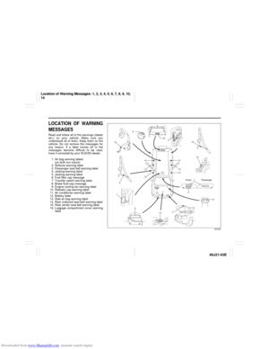 7
7 8
8 9
9 10
10 11
11 12
12 13
13 14
14 15
15 16
16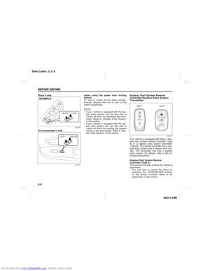 17
17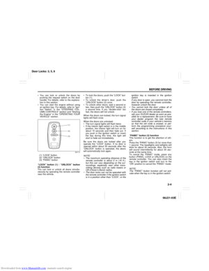 18
18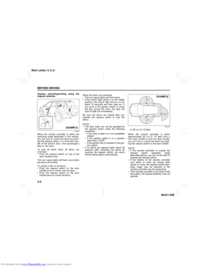 19
19 20
20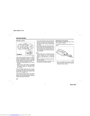 21
21 22
22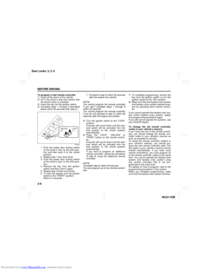 23
23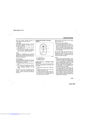 24
24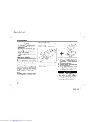 25
25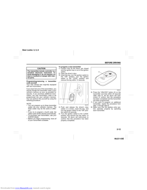 26
26 27
27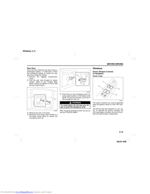 28
28 29
29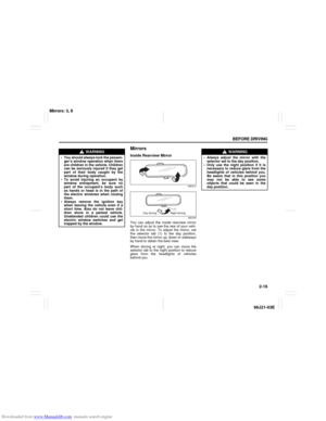 30
30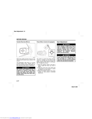 31
31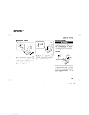 32
32 33
33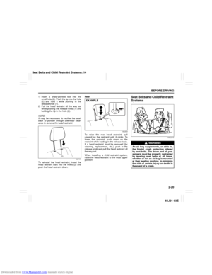 34
34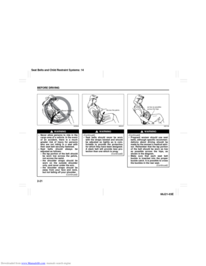 35
35 36
36 37
37 38
38 39
39 40
40 41
41 42
42 43
43 44
44 45
45 46
46 47
47 48
48 49
49 50
50 51
51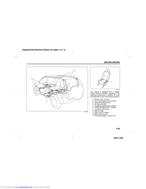 52
52 53
53 54
54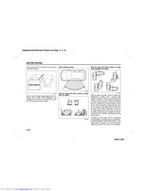 55
55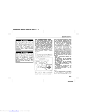 56
56 57
57 58
58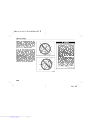 59
59 60
60 61
61 62
62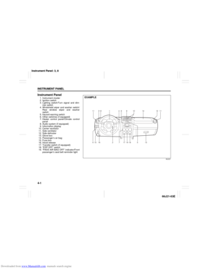 63
63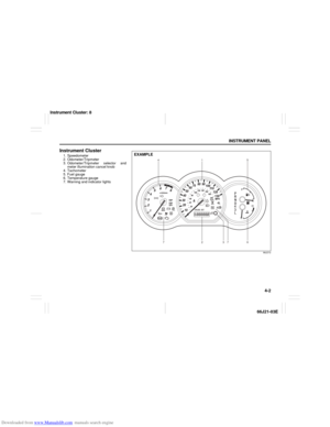 64
64 65
65 66
66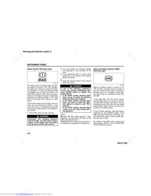 67
67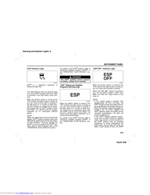 68
68 69
69 70
70 71
71 72
72 73
73 74
74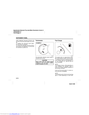 75
75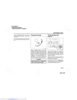 76
76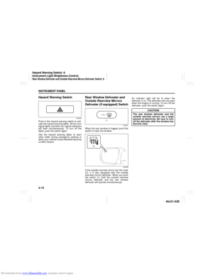 77
77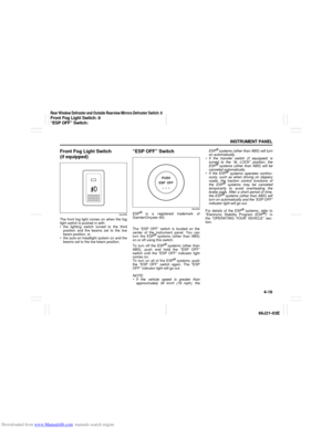 78
78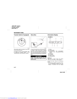 79
79 80
80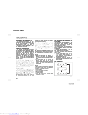 81
81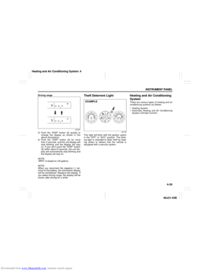 82
82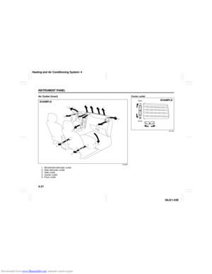 83
83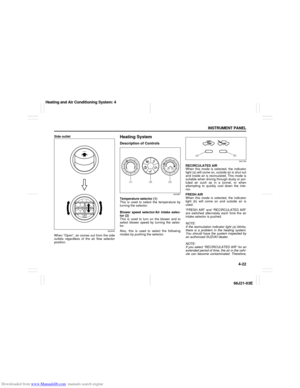 84
84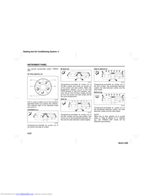 85
85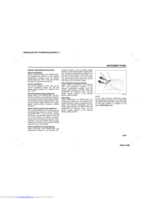 86
86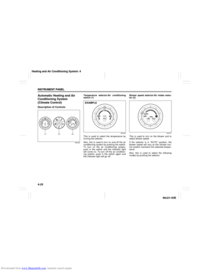 87
87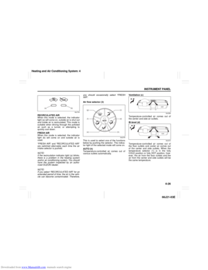 88
88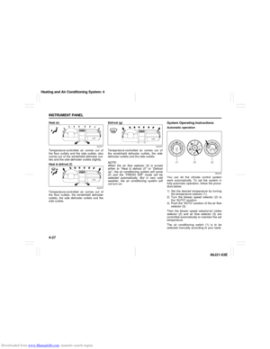 89
89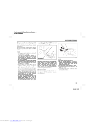 90
90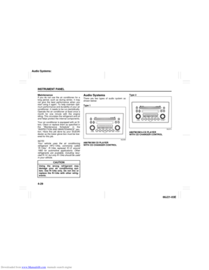 91
91 92
92 93
93 94
94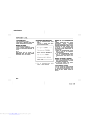 95
95 96
96 97
97 98
98 99
99 100
100 101
101 102
102 103
103 104
104 105
105 106
106 107
107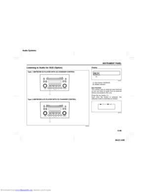 108
108 109
109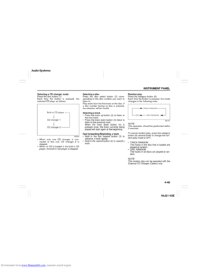 110
110 111
111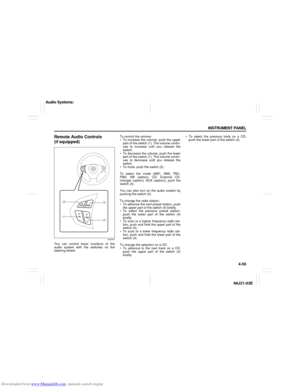 112
112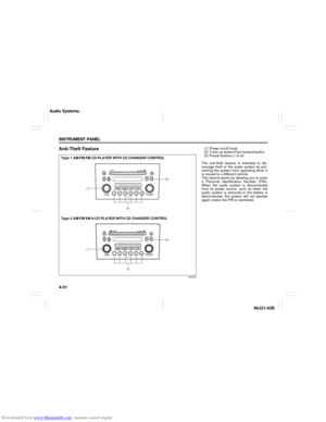 113
113 114
114 115
115 116
116 117
117 118
118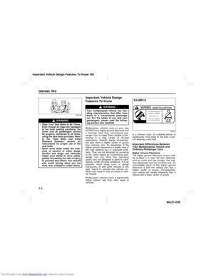 119
119 120
120 121
121 122
122 123
123 124
124 125
125 126
126 127
127 128
128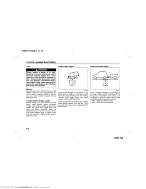 129
129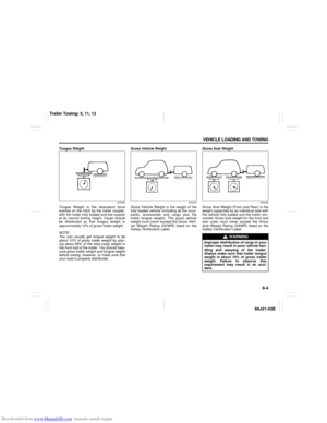 130
130 131
131 132
132 133
133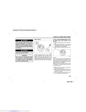 134
134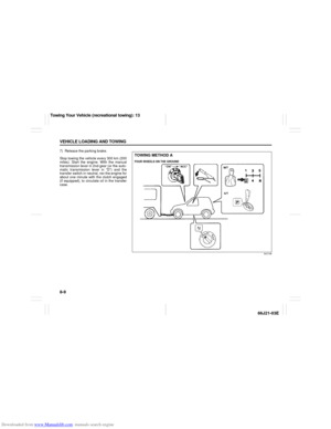 135
135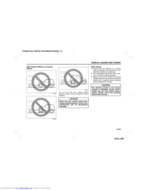 136
136 137
137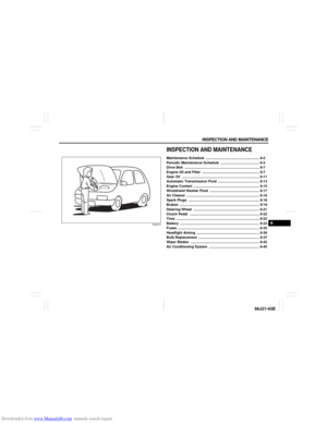 138
138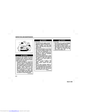 139
139 140
140 141
141 142
142 143
143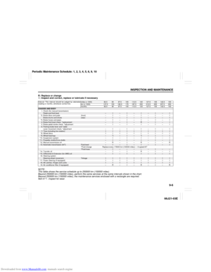 144
144 145
145 146
146 147
147 148
148 149
149 150
150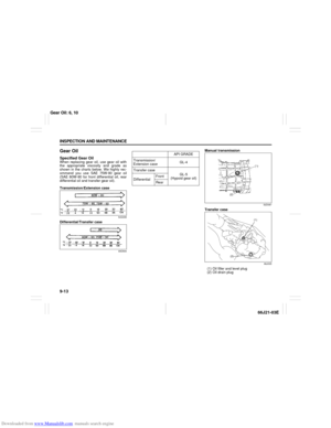 151
151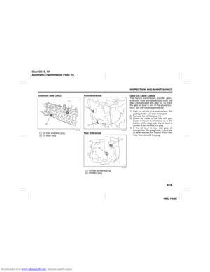 152
152 153
153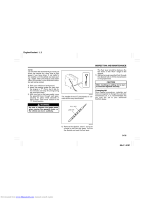 154
154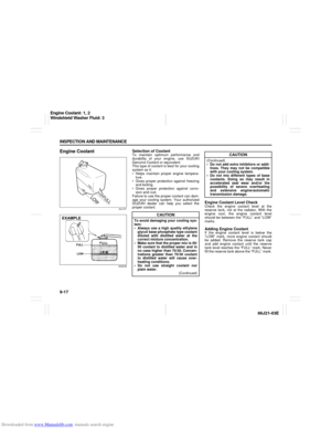 155
155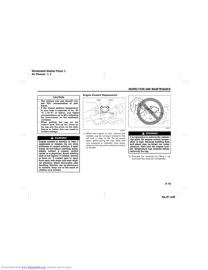 156
156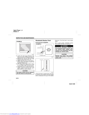 157
157 158
158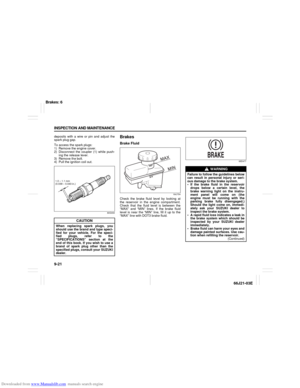 159
159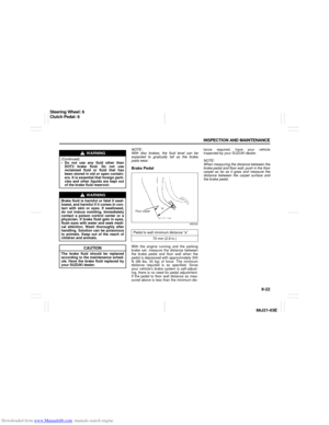 160
160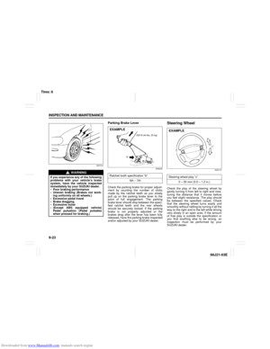 161
161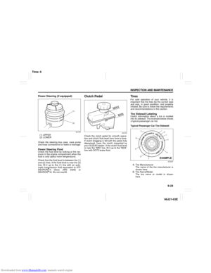 162
162 163
163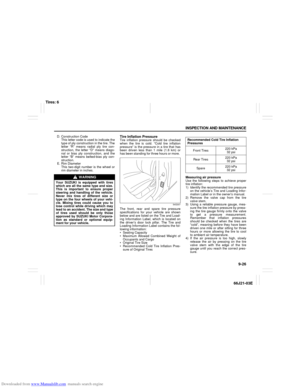 164
164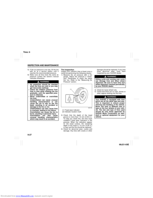 165
165 166
166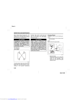 167
167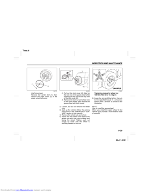 168
168 169
169 170
170 171
171 172
172 173
173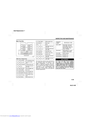 174
174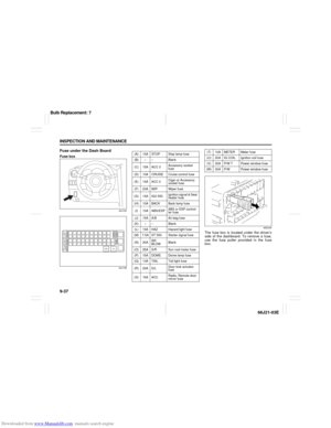 175
175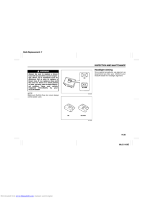 176
176 177
177 178
178 179
179 180
180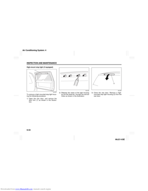 181
181 182
182 183
183 184
184 185
185 186
186 187
187 188
188 189
189 190
190 191
191 192
192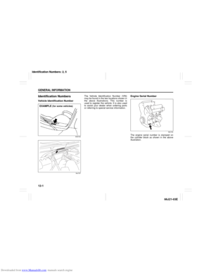 193
193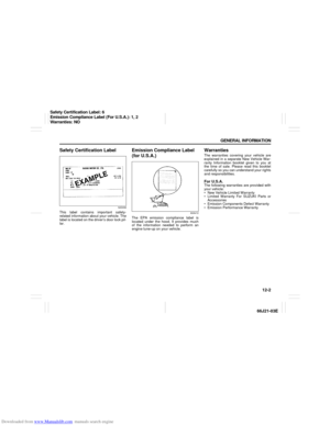 194
194 195
195 196
196 197
197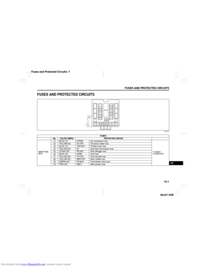 198
198 199
199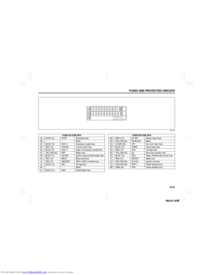 200
200 201
201 202
202 203
203 204
204 205
205 206
206 207
207 208
208 209
209 210
210