Page 161 of 211

Downloaded from www.Manualslib.com manuals search engine 9-23 INSPECTION AND MAINTENANCE
66J21-03E
60G104
Parking Brake Lever
60A226
Check the parking brake for proper adjust-
ment by counting the number of clicks
made by the ratchet teeth as you slowly
pull up on the parking brake lever to the
point of full engagement. The parking
brake lever should stop between the speci-
fied ratchet teeth and the rear wheels
should be securely locked. If the parking
brake is not properly adjusted or the
brakes drag after the lever has been fully
released, have the parking brake inspected
and/or adjusted by your SUZUKI dealer.
Steering Wheel
54G110
Check the play of the steering wheel by
gently turning it from left to right and mea-
suring the distance that it moves before
you feel slight resistance. The play should
be between the specified values. Check
that the steering wheel turns easily and
smoothly without rattling by turning it all the
way to the right and to the left while driving
very slowly in an open area. If the amount
of free play is outside the specification or
you find anything else to be wrong, an
inspection must be performed by your
SUZUKI dealer.
WARNING
If you experience any of the following
problems with your vehicle’s brake
system, have the vehicle inspected
immediately by your SUZUKI dealer.
Poor braking performance
Uneven braking (Brakes not work-
ing uniformly on all wheels.)
Excessive pedal travel
Brake dragging
Excessive noise
(Except ABS equipped vehicle)
Pedal pulsation (Pedal pulsates
when pressed for braking.)
Ratchet tooth specification “b”
5th – 7th
200 N (44 lbs, 20 kg)
“b”
EXAMPLE
Steering wheel play “c”
0 – 30 mm (0.0 – 1.2 in.)EXAMPLE
Tires: 6
Page 162 of 211

64J155
(1) UPPER
(2) LOWER
Check the steering box case, vane pump
and ho")
Downloaded from www.Manualslib.com manuals search engine 9-24 INSPECTION AND MAINTENANCE
66J21-03E
Power Steering (if equipped)
64J155
(1) UPPER
(2) LOWER
Check the steering box case, vane pump
and hose connections for leaks or damage.Power Steering FluidCheck the fluid level by looking at the res-
ervoir in the engine compartment when the
fluid is cold (about room temperature).
Check that the fluid level is between the (1)
and (2) lines. If the fluid level is near the (2)
line, fill it up to the (1) line with an auto-
matic transmission fluid equivalent to ATF
DEXRON
®-II (Esso JWS 2326) or
DEXRON®-III. Do not overfill.
Clutch Pedal
64J154
Check the clutch pedal for smooth opera-
tion and clutch fluid level from time to time.
If clutch dragging is felt with the pedal fully
depressed, have the clutch inspected by
your SUZUKI dealer. If the clutch fluid level
is near the “MIN” line, fill it up to the “MAX”
line with DOT3 brake fluid.
TiresFor safe operation of your vehicle, it is
important that the tires be the correct type
and size, in good condition, and properly
inflated. Be sure to follow the requirements
and recommendations in this section.Tire Sidewall LabelingUseful information about a tire is molded
into its sidewall. The example below shows
a typical passenger car tire.
Typical Passenger Car Tire Sidewall
67D027
A. Tire Manufacturer
The name of the tire manufacturer is
shown here.
B. Tire Name/Model
The tire name or model is shown
here.
(1)
(2)
AH B
G
E
FD
J I
C
EXAMPLE
Tires: 6
Page 163 of 211

Downloaded from www.Manualslib.com manuals search engine 9-25 INSPECTION AND MAINTENANCE
66J21-03E
C. Tire Size
The tire size code is a combination of
letters and numbers used to define a
particular tire’s width, height, aspect
ratio, construction type, and service
description. See the “Tire Size” expla-
nation later in this section for more
details.
D. U.S. DOT Tire Identification Number
The Department of Transportation
(DOT) marking indicates that the tire
is in compliance with the U.S. Depart-
ment of Transportation Motor Vehicle
Safety Standards. The letters and
numbers following the DOT marking
is the Tire Identification Number
(TIN). The TIN identifies the tire man-
ufacturer and plant, tire size, and date
the tire was manufactured.
E. Uniform Tire Quality Grading (UTQG)
Tire manufacturers are required to
grade tires based on three perfor-
mance factors: treadwear, traction
and temperature resistance. Refer to
the “Uniform Tire Quality Grading”
section for more details.
F. Load Rating
Load rating is the maximum weight a
tire is designed to support in normal
service.
G. Max Inflation Pressure
Max inflation pressure is the maxi-
mum inflation pressure a tire is
designed for.
H. Tire Ply Material
These tire markings describe the typeof cord and number of plies in the
sidewall and under the tread.
I. Load Index and Speed Rating
The two- or three-digit number is the
tire’s load index, the maximum load a
tire can carry at the speed indicated
by its speed symbol at the maximum
inflation pressure. The higher the
number is, the greater the load carry-
ing capacity. The letter symbol
denotes the speed at which a tire is
designed to be driven for extended
periods of time. (Ratings are listed
below.)
*The letters ZR may be used on tires with a
maximum speed capability over 149 mph
and will always be used on tires with a
maximum speed capability over 186 mph.J. M+S Marking
This marking indicates the tire has
some mud and snow capabilities and
is designed for all-season use.
Tire SizeThe following illustration shows an exam-
ple of a typical passenger car tire size.
67D028
A. Tire Type
This letter code indicates the primary
intended use of the tire. The letter “P”
identifies a tire primarily intended for
use on a passenger vehicle.
B. Tire Width
This three-digit number indicates the
tire section width in millimeters from
sidewall to sidewall.
C. Aspect Ratio
This two-digit number represents the
tire section height divided by the tire
section width. Letter Rating Speed Rating
Q 99 mph
R106 mph
S112 mph
T118 mph
U124 mph
H130 mph
V149 mph
W 168 mph*
Y 186 mph*
A
B
C
D
E
EXAMPLE
Tires: 6
Page 164 of 211

Downloaded from www.Manualslib.com manuals search engine 9-26 INSPECTION AND MAINTENANCE
66J21-03E
D. Construction Code
This letter code is used to indicate the
type of ply construction in the tire. The
letter “R” means radial ply tire con-
struction, the letter “D” means diago-
nal or bias ply construction, and the
letter “B” means belted-bias ply con-
struction.
E. Rim Diameter
This two-digit number is the wheel or
rim diameter in inches.
Tire Inflation PressureTire inflation pressure should be checked
when the tire is cold. “Cold tire inflation
pressure” is the pressure in a tire that has
been driven less than 1 mile (1.6 km) or
has been standing for three hours or more.
54G307
The front, rear and spare tire pressure
specifications for your vehicle are shown
below and are listed on the Tire and Load-
ing Information Label, which is located on
the driver’s door lock pillar. The Tire and
Loading Information Label contains the fol-
lowing information:
Seating Capacity
Maximum Allowed Combined Weight of
Occupants and Cargo
Original Tire Size
Recommended Cold Tire Inflation Pres-
sure of Original TiresMeasuring air pressure
Use the following steps to achieve proper
tire inflation:
1) Identify the recommended tire pressure
on the vehicle’s Tire and Loading Infor-
mation Label or in the owner’s manual.
2) Remove the valve cap from the tire
valve stem.
3) Using a reliable pressure gauge, mea-
sure the tire inflation pressure by press-
ing the tire gauge firmly onto the valve
to get a pressure measurement.
Remember that inflation pressures
should be checked when the tires are
“cold”, meaning before they have been
driven one mile or after sitting for three
hours or more allowing the tire to cool
to ambient air temperature.
4) If the air pressure is too high, slowly
release the air by pressing on the tire
valve stem with the edge of the tire
gauge until you reach the correct pres-
sure.
WARNING
Your SUZUKI is equipped with tires
which are all the same type and size.
This is important to ensure proper
steering and handling of the vehicle.
Never mix tires of different size or
type on the four wheels of your vehi-
cle. Mixing tires could cause you to
lose control while driving which may
lead to an accident. The size and type
of tires used should be only those
approved by SUZUKI Motor Corpora-
tion as standard or optional equip-
ment for your vehicle.
Recommended Cold Tire Inflation
Pressures
Front Tires220 kPa
32 psi
Rear Tires220 kPa
32 psi
Spare220 kPa
32 psi
Tires: 6
Page 165 of 211
 If the air pressure is too low, fill the tire
with air at a service station until it
reaches the r")
Downloaded from www.Manualslib.com manuals search engine 9-27 INSPECTION AND MAINTENANCE
66J21-03E
5) If the air pressure is too low, fill the tire
with air at a service station until it
reaches the recommended pressure.
6) Make sure all tires have the same air
pressure (unless the owner’s manual
indicates otherwise).
Tire InspectionInspect your vehicle’s tires at least once a
month by performing the following checks:
1) Measure the air pressure with a tire
gauge. Adjust the pressure if neces-
sary. Remember to check the spare
tire, too. Refer to the “Measuring Air
Pressure” section.
54G136
(1) Tread wear indicator
(2) Indicator location mark
2) Check that the depth of the tread
groove is more than 1.6 mm (0.06 in.).
To help you check this, the tires have
molded-in tread wear indicators in the
grooves. When the indicators appear
on the tread surface, the remaining
depth of the tread is 1.6 mm (0.06 in.)
or less and the tire should be replaced.
3) Check for abnormal wear, cracks and
damage. Any tires with cracks or otherdamage should be replaced. If any tires
show abnormal wear, have them
inspected by your SUZUKI dealer.
4) Check for loose wheel nuts.
5) Check that there are no nails, stones or
other objects sticking into the tires.
WARNING
Air pressures should be checked
when the tires are cold or you may
get inaccurate readings.
Check the inflation pressure from
time to time while inflating the tire
gradually, until the specified pres-
sure is obtained.
Never underinflate or overinflate
the tires.
Underinflation can cause unusual
handling characteristics or can
cause the rim to slip on the tire
bead, resulting in an accident or
damage to the tire or rim.
Underinflation can also cause tires
to overheat, leading to tire failure.
Overinflation can cause the tire to
burst, resulting in personal injury.
Overinflation can also cause
unusual handling characteristics
which may result in an accident.
WARNING
Hitting curbs and running over rocks
can damage tires and affect wheel
alignment. Be sure to have tires and
wheel alignment checked periodically
by your SUZUKI dealer.
WARNING
Your SUZUKI is equipped with tires
which are all the same type and size.
This is important to ensure proper
steering and handling of the vehicle.
Never mix tires of different size or
type on the four wheels of your vehi-
cle. The size and type of tires used
should be only those approved by
SUZUKI Motor Corporation as stan-
dard or optional equipment for your
vehicle.
Tires: 6
Page 166 of 211

Downloaded from www.Manualslib.com manuals search engine 9-28 INSPECTION AND MAINTENANCE
66J21-03E
Uniform Tire Quality GradingThe U.S. National Highway Traffic Safety
Administration has developed a grading
system for evaluating the performance of
passenger car tires. The following informa-
tion will help you understand the grading
system, which applies to vehicles sold in
the U.S. Consult your SUZUKI dealer or
tire retailer for help in choosing the correct
replacement tires for your vehicle.
Quality grades can be found where appli-
cable on the tire sidewall between tread
shoulder and maximum section width. For
example:
Treadwear 200 Traction AA Temperature ADOT Quality Grades
Treadwear
Traction AA A B C
Temperature A B CAll Passenger Car Tires Must Conform To
Federal Safety Requirements in Addition
To These Grades
Treadwear
The treadwear grade is a comparative rat-
ing based on the wear rate of the tire when
tested under controlled conditions on a
specified government test course. For
example, a tire graded 150 would wear one
and one-half (1 1/2) times as well on the
government course as a tire graded 100.
The relative performance of tires depends
upon the actual conditions of their use,
however and may depart significantly fromthe norm due to variations in driving habits,
service practices and differences in road
characteristics and climate.
Traction – AA, A, B, C
The traction grades, from highest to low-
est, are AA, A, B and C. Those grades rep-
resent the tire’s ability to stop on wet
pavement as measured under controlled
conditions on specified government test
surfaces of asphalt and concrete. A tire
marked C may have poor traction perfor-
mance.
Temperature – A, B, C
The temperature grades are A (the high-
est), B and C, representing the tire’s resis-
tance to the generation of heat and its
ability to dissipate heat when tested under
controlled conditions on a specified indoor
laboratory test wheel. Sustained high tem-
perature can cause the material of the tire
to degenerate and reduce tire life, and
excessive temperature can lead to sudden
tire failure. The grade C corresponds to a
level of performance which all passenger
car tires must meet under the Federal
WARNING
Replacing the wheels and tires
equipped on your vehicle with certain
combinations of aftermarket wheels
and tires can significantly change the
steering and handling characteris-
tics of your vehicle. Oversized tires
may also rub against the fender over
bumps, causing vehicle damage or
tire failure. Therefore, use only those
wheel and tire combinations
approved by SUZUKI Motor Corpora-
tion as standard or optional equip-
ment for your vehicle. For
information regarding the specified
tires, refer to the Tire Information
Label located on the driver’s side
door pillar or the “SPECIFICATIONS”
section.
CAUTION
Replacing the original tires with tires
of a different size may result in false
speedometer or odometer readings.
Check with your SUZUKI dealer
before purchasing replacement tires
that differ in size from the original
tires.
WARNING
The traction grade assigned to this
tire is based on straight-ahead brak-
ing traction tests, and does not
include acceleration, cornering,
hydroplaning or peak traction charac-
teristics.
Tires: 6
Page 167 of 211

Downloaded from www.Manualslib.com manuals search engine 9-29 INSPECTION AND MAINTENANCE
66J21-03E
Motor Vehicle Safety Standard No. 109.
Grades B and A represent higher levels of
performance on the laboratory test wheel
than the minimum required by law.Tire Rotation4-tire rotation
65D459
To avoid uneven wear of your tires and to
prolong their life, rotate the tires as illus-
trated. Tires should be rotated as recom-
mended in the periodic maintenanceschedule. After rotation, adjust front and
rear tire pressures to the specification
listed on your vehicle’s Tire and Loading
Information Label.
Changing WheelsTo change a wheel, use the following pro-
cedure:
1) Remove the jack, tools and spare wheel
from the vehicle.
NOTE:
How to remove the spare wheel:
64J178
1. (Full cover type)
Release the lock at the underneath
of the spare wheel full cover (A) as
shown in the illustration, then
remove the outer cover of the spare
wheel full cover.
WARNING
The temperature grade for this tire is
established for a tire that is properly
inflated and not overloaded. Exces-
sive speed, underinflation or exces-
sive loading, either separately or in
combination, can cause heat buildup
and possible tire failure.
WARNING
Rust or dirt on a wheel, or on the
parts to which it is fastened, can
make wheel nuts become loose after
a time. The wheel could come off and
cause an accident. When you change
a wheel, remove any rust or dirt from
places where the wheel attaches to
the vehicle. In an emergency, you can
use a cloth or a paper towel to do
this; but be sure to use a scraper or
wire brush later, if you need to, to get
all the rust or dirt off.
(A)
Tires: 6
Page 168 of 211

Remove the center bolt (1), then
remove the outer cover (2) of the
spare wh")
Downloaded from www.Manualslib.com manuals search engine 9-30 INSPECTION AND MAINTENANCE
66J21-03E
64J179
(Half cover type)
Remove the center bolt (1), then
remove the outer cover (2) of the
spare wheel half cover.
64J180
2. Pull out the lock cover (B) fitted on
the lock nut of the spare wheel while
inserting the key full into the key hole
of the lock cover (B).
3. Remove the lock nut and wheel nuts
of the spare wheel, then remove the
spare wheel with both hands.
2) Loosen, but do not remove the wheel
nuts.
3) Jack up the vehicle (follow the jacking
instructions in the “EMERGENCY SER-
VICE” section in this manual).
4) Remove the wheel nuts and wheel.
5) Install the new wheel and replace the
wheel nuts with their cone shaped end
facing the wheel. Tighten each nut
snugly by hand until the wheel is
securely seated on the hub.
81A057
Tightening torque for wheel nut
100 Nm (72.3 lb-ft, 10.0 kg-m)
6) Lower the jack and fully tighten the nuts
to the specified torque in a crisscross
fashion with a wrench as shown in the
illustration.
NOTE:
How to install the spare wheel:
When you install the spare wheel to the
vehicle again, handle it in the reverse order
of removal.
(2) (1)
(B)
EXAMPLE
Tires: 6
 1
1 2
2 3
3 4
4 5
5 6
6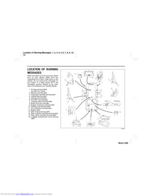 7
7 8
8 9
9 10
10 11
11 12
12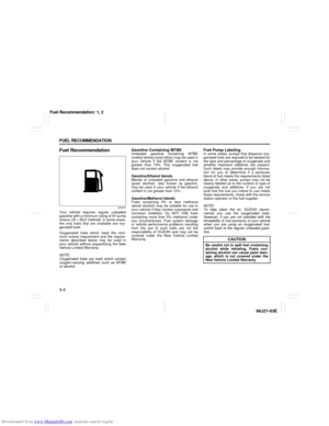 13
13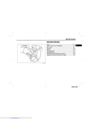 14
14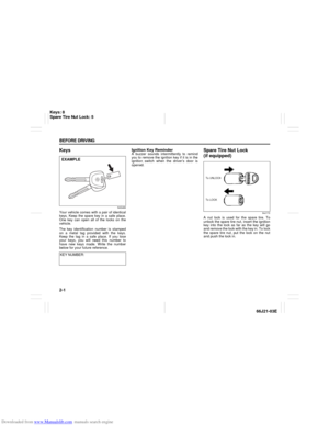 15
15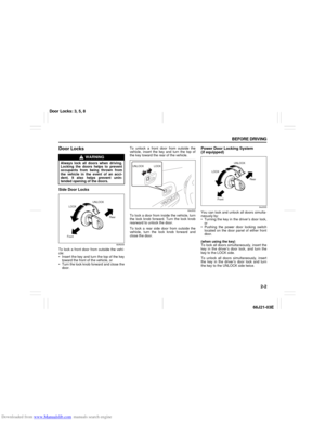 16
16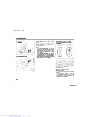 17
17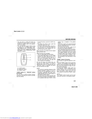 18
18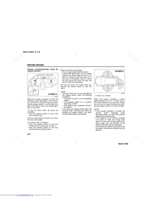 19
19 20
20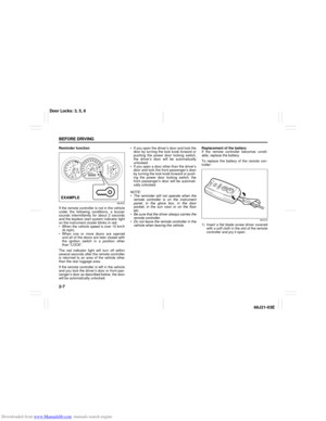 21
21 22
22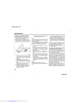 23
23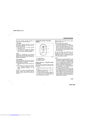 24
24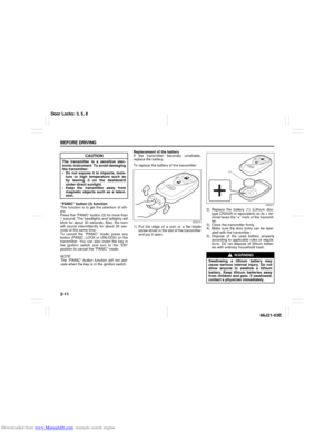 25
25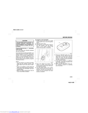 26
26 27
27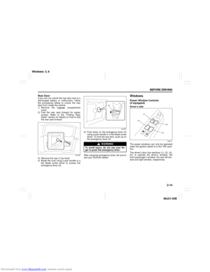 28
28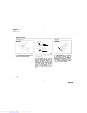 29
29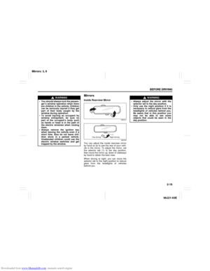 30
30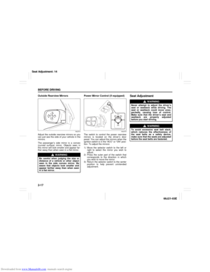 31
31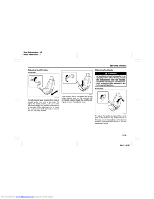 32
32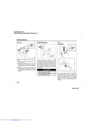 33
33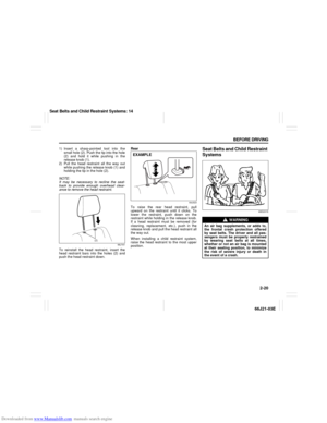 34
34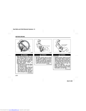 35
35 36
36 37
37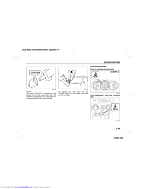 38
38 39
39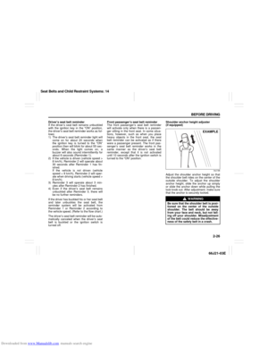 40
40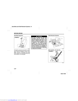 41
41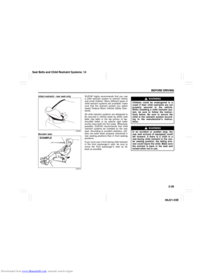 42
42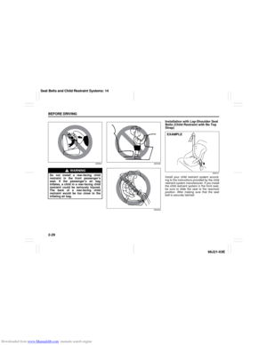 43
43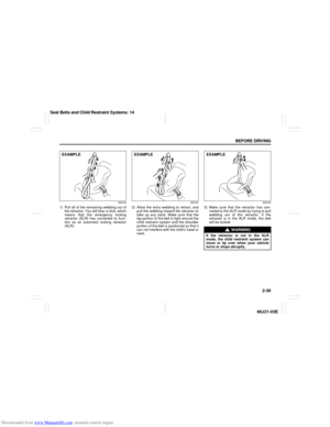 44
44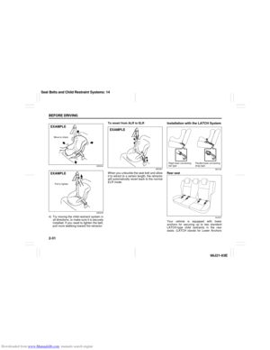 45
45 46
46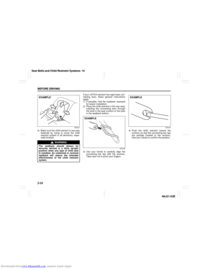 47
47 48
48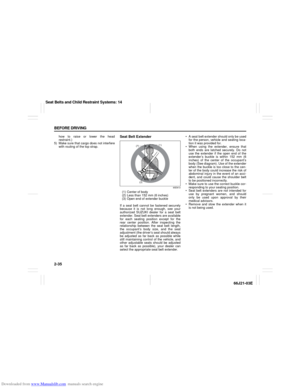 49
49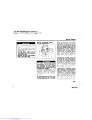 50
50 51
51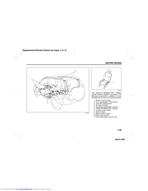 52
52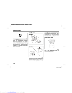 53
53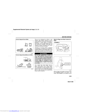 54
54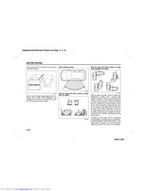 55
55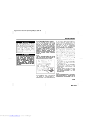 56
56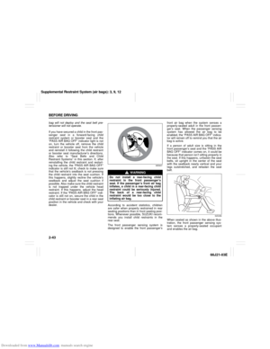 57
57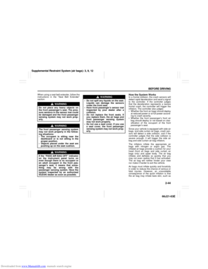 58
58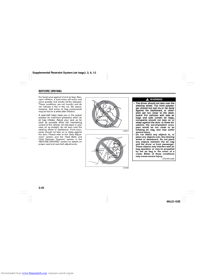 59
59 60
60 61
61 62
62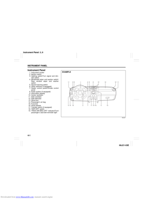 63
63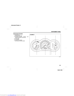 64
64 65
65 66
66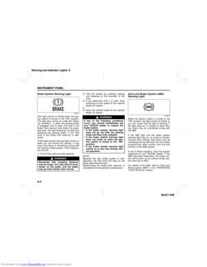 67
67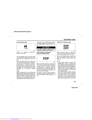 68
68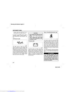 69
69 70
70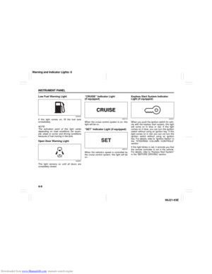 71
71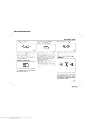 72
72 73
73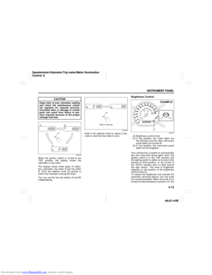 74
74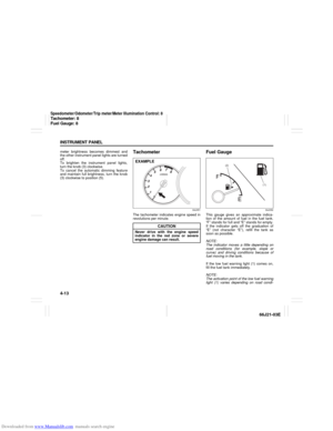 75
75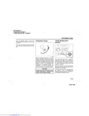 76
76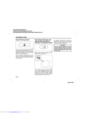 77
77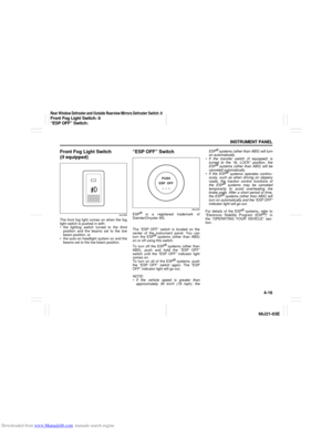 78
78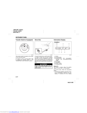 79
79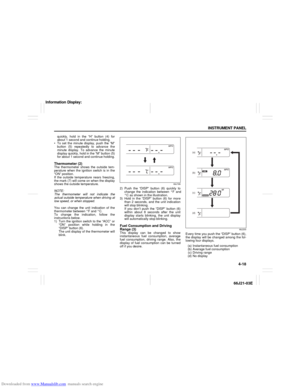 80
80 81
81 82
82 83
83 84
84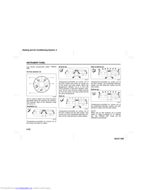 85
85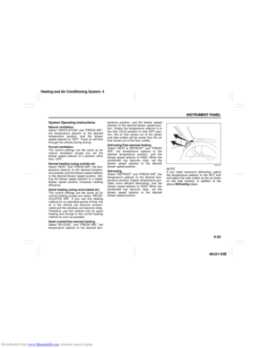 86
86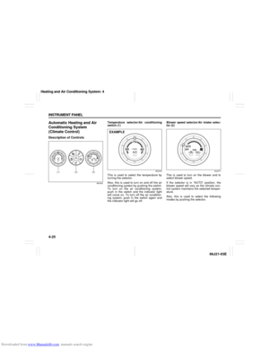 87
87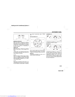 88
88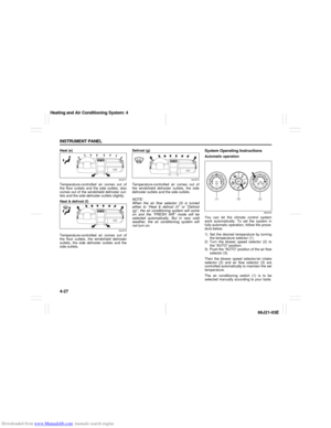 89
89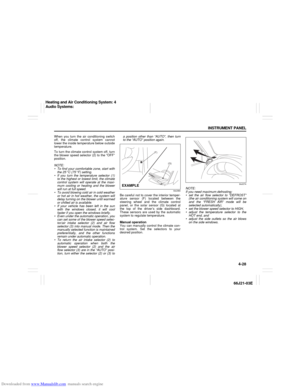 90
90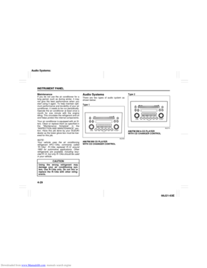 91
91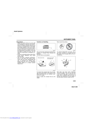 92
92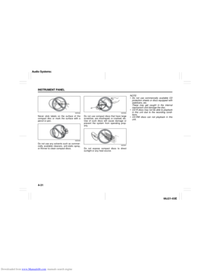 93
93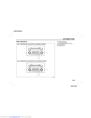 94
94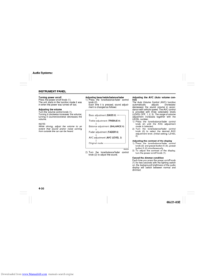 95
95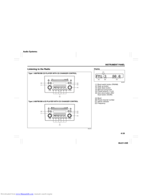 96
96 97
97 98
98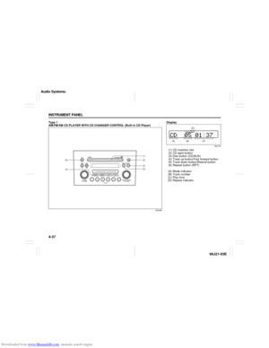 99
99 100
100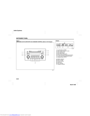 101
101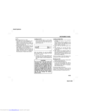 102
102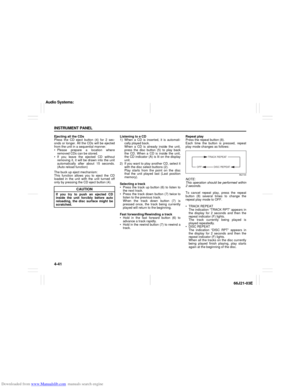 103
103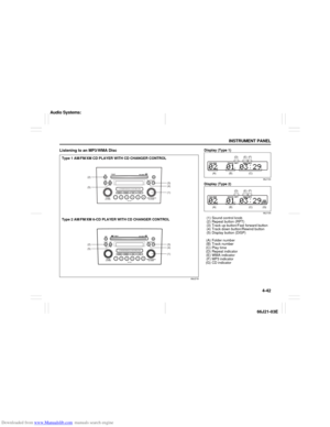 104
104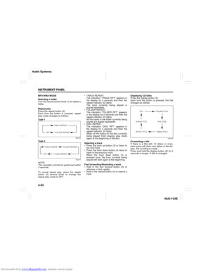 105
105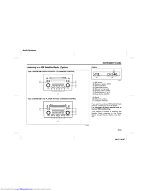 106
106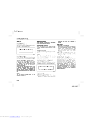 107
107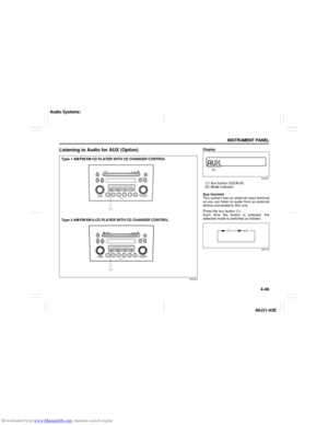 108
108 109
109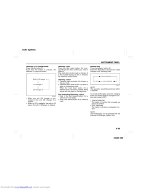 110
110 111
111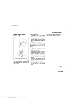 112
112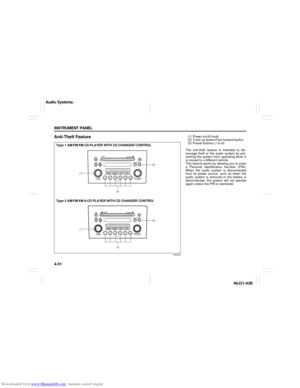 113
113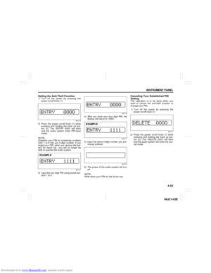 114
114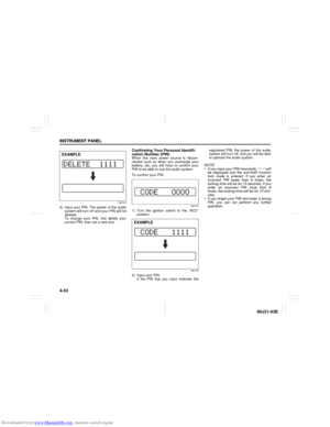 115
115 116
116 117
117 118
118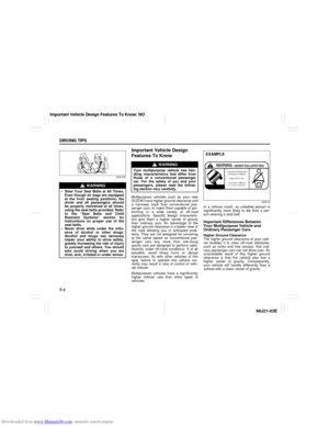 119
119 120
120 121
121 122
122 123
123 124
124 125
125 126
126 127
127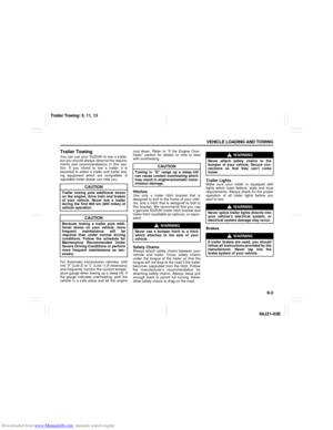 128
128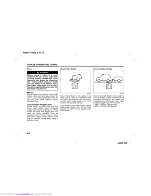 129
129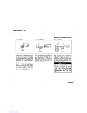 130
130 131
131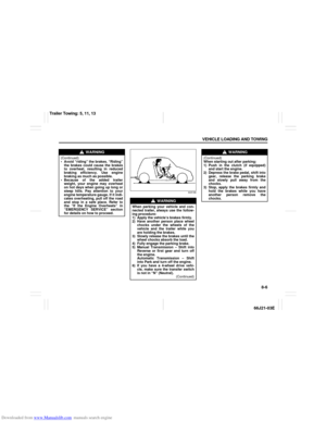 132
132 133
133 134
134 135
135 136
136 137
137 138
138 139
139 140
140 141
141 142
142 143
143 144
144 145
145 146
146 147
147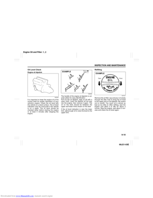 148
148 149
149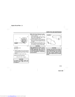 150
150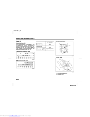 151
151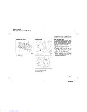 152
152 153
153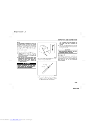 154
154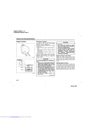 155
155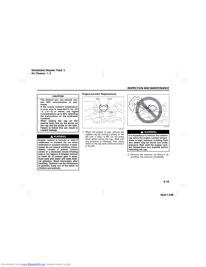 156
156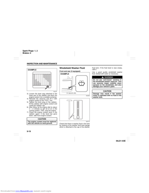 157
157 158
158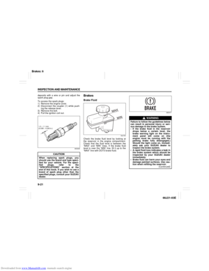 159
159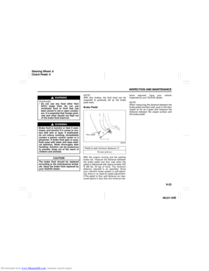 160
160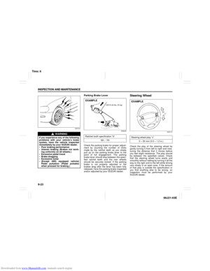 161
161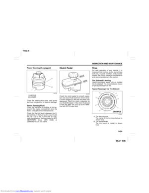 162
162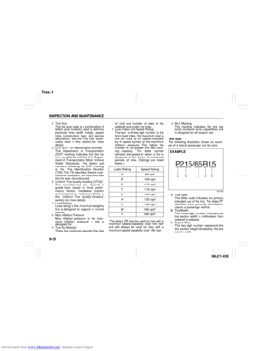 163
163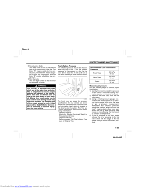 164
164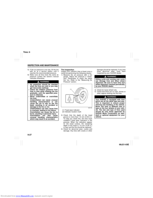 165
165 166
166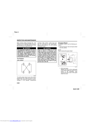 167
167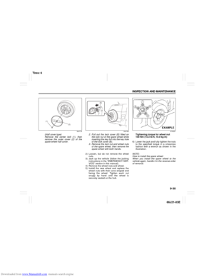 168
168 169
169 170
170 171
171 172
172 173
173 174
174 175
175 176
176 177
177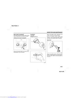 178
178 179
179 180
180 181
181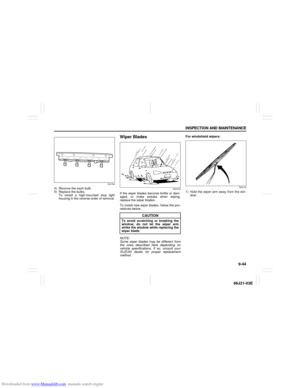 182
182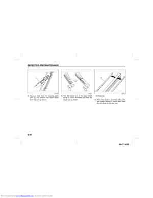 183
183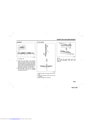 184
184 185
185 186
186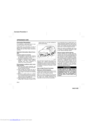 187
187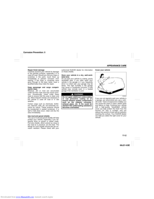 188
188 189
189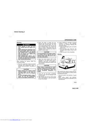 190
190 191
191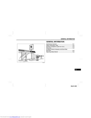 192
192 193
193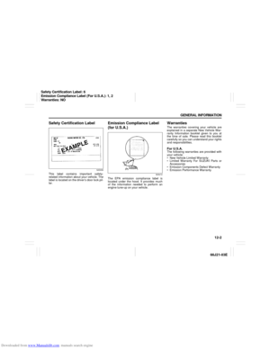 194
194 195
195 196
196 197
197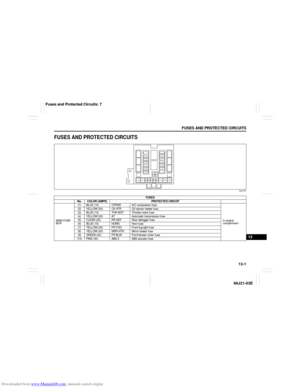 198
198 199
199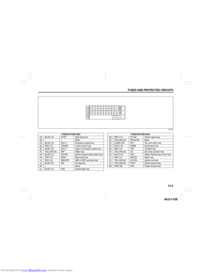 200
200 201
201 202
202 203
203 204
204 205
205 206
206 207
207 208
208 209
209 210
210