2007 SUZUKI AERIO specifications
[x] Cancel search: specificationsPage 5 of 232
Downloaded from www.Manualslib.com manuals search engine 54G27-03E
TABLE OF CONTENTSCalifornia Proposition 65 Warning
WARNING
Engine exhaust, some of its constitu-
ents, and certain product compo-
nents contain or emit chemicals
known to the State of California to
cause cancer and birth defects or
other reproductive harm.
FUEL RECOMMENDATION
1
BEFORE DRIVING
2
STEERING COLUMN CONTROLS
3
INSTRUMENT PANEL
4
OTHER CONTROLS AND EQUIPMENT
5
OPERATING YOUR VEHICLE
6
DRIVING TIPS
7
VEHICLE LOADING AND TOWING
8
INSPECTION AND MAINTENANCE
9
EMERGENCY SERVICE
10
APPEARANCE CARE
11
GENERAL INFORMATION
12
FUSES AND PROTECTED CIRCUITS
13
SPECIFICATIONS
14
INDEX
15
Page 19 of 232

Downloaded from www.Manualslib.com manuals search engine 2-6 BEFORE DRIVING
54G27-03E
To change the old transmitter codes in
your vehicle’s memory
If you have lost one of the transmitters, you
should change the transmitter codes in
your vehicle’s memory as soon as possible
for security.
To remove one of the transmitter codes
from your vehicle’s memory, first replace all
three of the transmitter codes in your vehi-
cle’s memory, then program additional
transmitters as follows:
1) Program one of your transmitters four
times, by repeating the programming
procedure shown in this section. This
will replace all the old transmitter codes
in the vehicle’s memory with the code
for the transmitter you are using.
2) If you want to program up to two addi-
tional transmitters, repeat the program-
ming procedure shown in this section.
3) Make sure that the keyless entry sys-
tem operates properly by operating
each transmitter.1. For USA
This device complies with Part 15 of the
FCC Rules. Operation is subject to the fol-
lowing two conditions:
1) this device may not cause harmful inter-
ference, and
2) this device must accept any interfer-
ence received, including interference
that may cause undesired operation.
NOTE:
Changes or modifications not expressly
approved by the party responsible for com-
pliance could void the user’s authority to
operate the equipment.
2. For Canada
This device complies with Industry Canada
Standard RSS-210. Operation is subject to
the following two conditions:
1) this device may not cause interference,
and
2) this device must accept any interfer-
ence, including interference that may
cause undesired operation of the
device.
The term “IC:” before the certification/reg-
istration number only signifies that the
Industry Canada technical specifications
were met.
Child Lock System (rear side doors)
54G574
Each of the rear side doors is equipped
with a child lock which can be used to help
prevent unwanted opening of the door from
inside the vehicle. When the lock lever is in
the “LOCK” position (1), the rear side door
can only be opened from outside. When
the lock lever is in the “UNLOCK” position
(2), the rear side door can be opened from
inside or outside.
WARNING
Be sure to place the child lock in the
“LOCK” position whenever children
are seated in the rear.
(1)(2)
EXAMPLE
Door Locks: 3, 5, 8
Page 166 of 232

Downloaded from www.Manualslib.com manuals search engine 9-13 INSPECTION AND MAINTENANCE
54G27-03E
Replace the Oil Filter
60A198
1) Using an oil filter wrench, turn the oil fil-
ter counterclockwise and remove it.
2) Using a clean rag, wipe off the mount-
ing surface on the engine where the
new filter will be seated.
3) Smear a little engine oil around the rub-
ber gasket of the new oil filter.
4) Screw on the new filter by hand until
the filter gasket contacts the mounting
surface.
54G093
(1) Oil filter
(2) 3/4 turn
5) Tighten the filter 3/4 turn from the point
of contact with the mounting surface (or
to the specified torque) using an oil filter
wrench.
Refill with Oil and Check for Leaks1) Pour oil through the filler hole and
install the filler cap.
For the approximate capacity of the oil,
refer to the “Capacities” item in the
“SPECIFICATIONS” section.
2) Start the engine and look carefully for
leaks at the oil filter and drain plug. Run
the engine at various speeds for at
least 5 minutes.
3) Stop the engine and wait about 5 min-
utes. Check the oil level again and add
oil if necessary. Check for leaks again.
CAUTION
To tighten the oil filter properly, it is
important to accurately identify the
position at which the filter gasket
first contacts the mounting surface.
Tightening torque specification
14 Nm (10.0 lb-ft, 1.4 kg-m)
CAUTION
To prevent oil leakage, make sure
that the oil filter is tight, but do not
overtighten it.
CAUTION
When replacing the oil filter, it is rec-
ommended that you use a genuine
SUZUKI replacement filter. If you use
an after-market filter, make sure it is
of equivalent quality and carefully fol-
low the manufacturer’s instructions
and precautions.
Automatic Transaxle Fluid: 10
Engine Coolant: 1, 2
Page 174 of 232
Downloaded from www.Manualslib.com manuals search engine 9-21 INSPECTION AND MAINTENANCE
54G27-03E
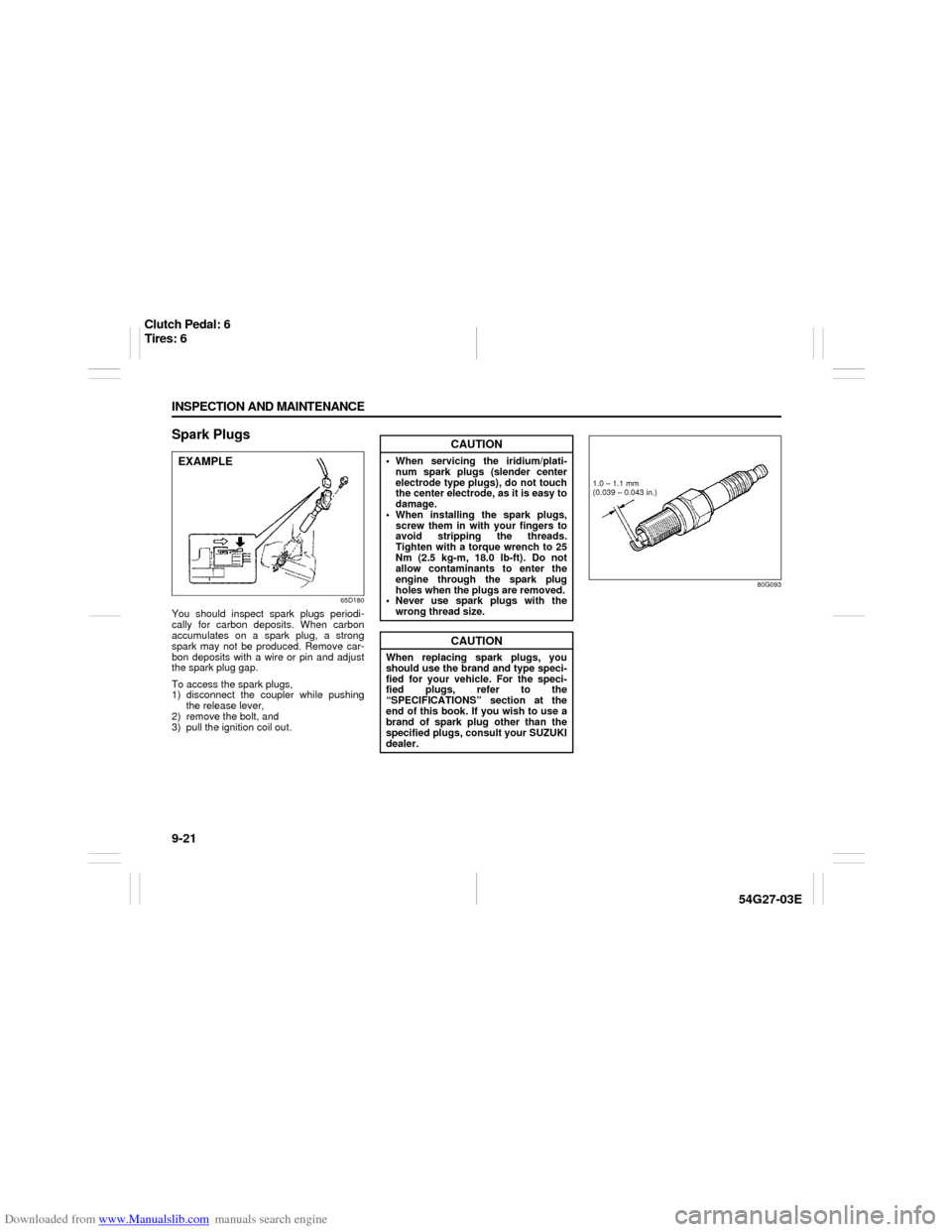
Spark Plugs
65D180
You should inspect spark plugs periodi-
cally for carbon deposits. When carbon
accumulates on a spark plug, a strong
spark may not be produced. Remove car-
bon deposits with a wire or pin and adjust
the spark plug gap.
To access the spark plugs,
1) disconnect the coupler while pushing
the release lever,
2) remove the bolt, and
3) pull the ignition coil out.
80G093
EXAMPLE
CAUTION
When servicing the iridium/plati-
num spark plugs (slender center
electrode type plugs), do not touch
the center electrode, as it is easy to
damage.
When installing the spark plugs,
screw them in with your fingers to
avoid stripping the threads.
Tighten with a torque wrench to 25
Nm (2.5 kg-m, 18.0 lb-ft). Do not
allow contaminants to enter the
engine through the spark plug
holes when the plugs are removed.
Never use spark plugs with the
wrong thread size.
CAUTION
When replacing spark plugs, you
should use the brand and type speci-
fied for your vehicle. For the speci-
fied plugs, refer to the
“SPECIFICATIONS” section at the
end of this book. If you wish to use a
brand of spark plug other than the
specified plugs, consult your SUZUKI
dealer.
1.0 – 1.1 mm
(0.039 – 0.043 in.)
Clutch Pedal: 6
Tires: 6
Page 181 of 232

Downloaded from www.Manualslib.com manuals search engine 9-28 INSPECTION AND MAINTENANCE
54G27-03E
sary. Remember to check the spare
tire, too. Refer to the “Measuring Air
Pressure” section.
54G136
(1) Tread wear indicator
(2) Indicator location mark
2) Check that the depth of the tread
groove is more than 1.6 mm (0.06 in.).
To help you check this, the tires have
molded-in tread wear indicators in the
grooves. When the indicators appear
on the tread surface, the remaining
depth of the tread is 1.6 mm (0.06 in.)
or less and the tire should be replaced.
3) Check for abnormal wear, cracks and
damage. Any tires with cracks or other
damage should be replaced. If any tires
show abnormal wear, have them
inspected by your SUZUKI dealer.4) Check for loose wheel nuts.
5) Check that there are no nails, stones or
other objects sticking into the tires.
WARNING
Hitting curbs and running over rocks
can damage tires and affect wheel
alignment. Be sure to have tires and
wheel alignment checked periodi-
cally by your SUZUKI dealer.
WARNING
Your SUZUKI is equipped with tires
which are all the same type and size.
This is important to ensure proper
steering and handling of the vehicle.
Never mix tires of different size or
type on the four wheels of your vehi-
cle. The size and type of tires used
should be only those approved by
SUZUKI Motor Corporation as stan-
dard or optional equipment for your
vehicle.
CAUTION
For All-wheel drive (AWD) models,
replacing a tire with one of a different
size, or using different brands among
the four tires can result in damage to
the drive train.
WARNING
Replacing the wheels and tires
equipped on your vehicle with certain
combinations of aftermarket wheels
and tires can significantly change the
steering and handling characteristics
of your vehicle. Oversized tires may
also rub against the fender over
bumps, causing vehicle damage or
tire failure. Therefore, use only those
wheel and tire combinations
approved by SUZUKI Motor Corpora-
tion as standard or optional equip-
ment for your vehicle. For
information regarding the specified
tires, refer to the Tire Information
Label located on the driver’s side
door pillar or the “SPECIFICATIONS”
section.
CAUTION
Replacing the original tires with tires
of a different size may result in false
speedometer or odometer readings.
Check with your SUZUKI dealer
before purchasing replacement tires
that differ in size from the original
tires.
Tires: 6
Page 194 of 232
Downloaded from www.Manualslib.com manuals search engine 9-41 INSPECTION AND MAINTENANCE
54G27-03E
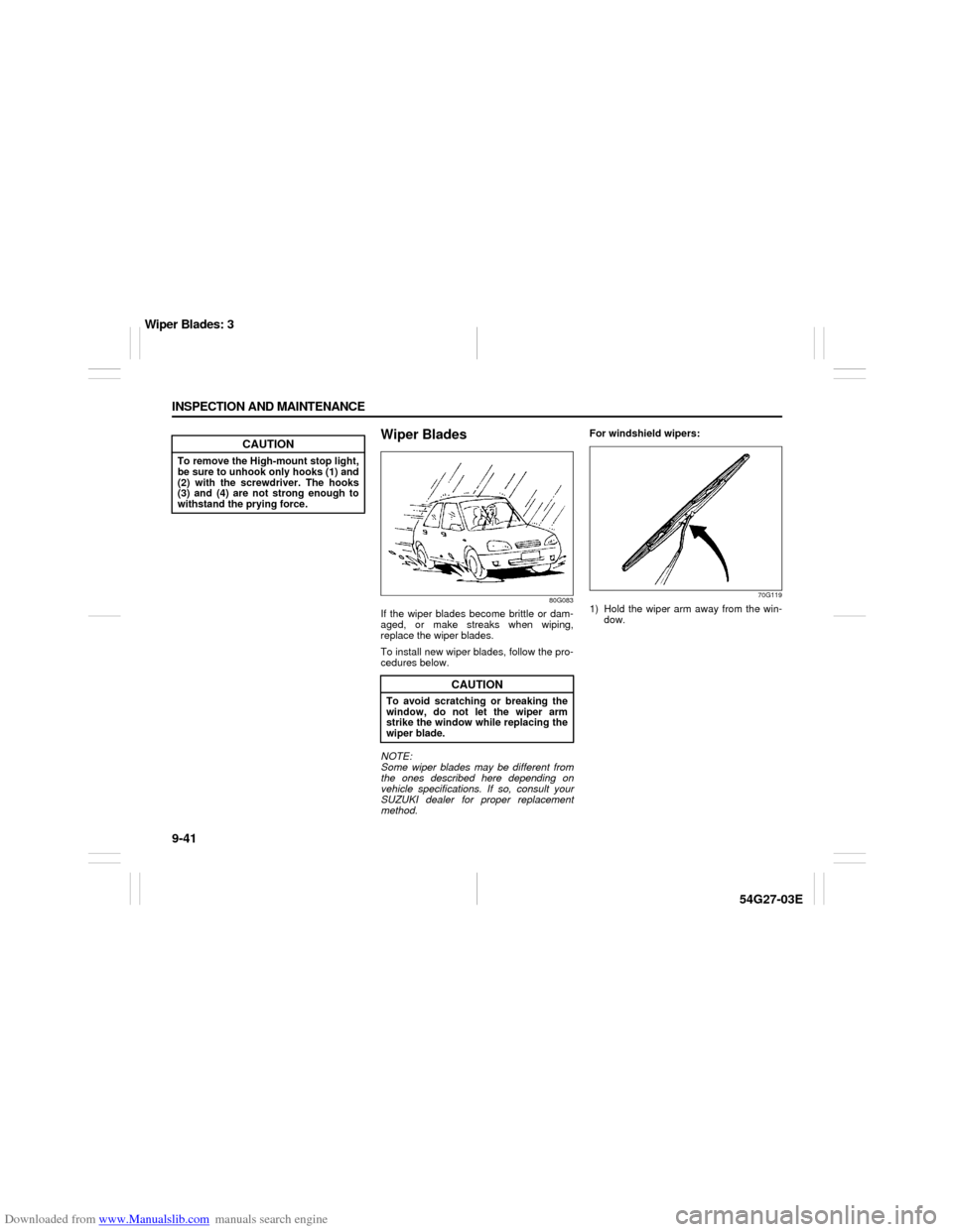
Wiper Blades
80G083
If the wiper blades become brittle or dam-
aged, or make streaks when wiping,
replace the wiper blades.
To install new wiper blades, follow the pro-
cedures below.
NOTE:
Some wiper blades may be different from
the ones described here depending on
vehicle specifications. If so, consult your
SUZUKI dealer for proper replacement
method.For windshield wipers:
70G119
1) Hold the wiper arm away from the win-
dow.
CAUTION
To remove the High-mount stop light,
be sure to unhook only hooks (1) and
(2) with the screwdriver. The hooks
(3) and (4) are not strong enough to
withstand the prying force.
CAUTION
To avoid scratching or breaking the
window, do not let the wiper arm
strike the window while replacing the
wiper blade.
Wiper Blades: 3
Page 223 of 232

Downloaded from www.Manualslib.com manuals search engine 14-1 SPECIFICATIONS
54G27-03E
14
SPECIFICATIONSNOTE:
Specifications are subject to change without notice.
4WD: 4-wheel drive
2WD: 2-wheel drive
ITEM: Dimensions UNIT: mm (in.)
Overall length4350 (171.3)
Overall width without side mold 1690 (66.5)
with side mold 1720 (67.7)
Overall height1545 (60.8)
Wheelbase2480 (97.6)
Tread Front 1450 (57.1)
Rear 1445 (56.9)
Minimum ground clearance 150 (5.9)
ITEM: Weight
Gross axle weight rating
See the safety certification label and the tire information label which
are located on the driver’s door lock pillar. Gross vehicle weight rating
Vehicle capacity weight
Specifications: 1, 2, 5, 6, 7, 10, 11
Page 224 of 232

Downloaded from www.Manualslib.com manuals search engine 14-2 SPECIFICATIONS
54G27-03E
ITEM: Engine
Type J23A (16 valve DOHC)
Number of cylinders 4
Bore 90.0 mm (3.54 in.)
Stroke 90.0 mm (3.54 in.)
Piston displacement 2290 cm
3 (139.7 cu.in, 2290 cc)
Compression ratio 9.3 : 1
ITEM: Electrical
Ignition timing 3° – 17° B.T.D.C. at idle speed
Standard spark plug NGK IFR5J11
Battery GP24 12V
Fuses See “INSPECTION AND MAINTENANCE” and “FUSES AND PRO-
TECTED CIRCUITS” sections.
Specifications: 1, 2, 5, 6, 7, 10, 11