Page 354 of 465

0-15
ABS SYSTEM
RODIUS 2006.09
4892-01
3. ABS SYSTEM DESCRIPTION
1) EBD (ELECTRONIC BRAKE FORCE DISTRIBUTION) SYSTEM
(1) System Description
As an add-on logic to the ABS base algorithm, EBD works in a range in which the intervention
thresholds for ABS control can not be reached. EBD ensures that the rear wheels are
sensitively monitored for slip with respect to the front axle. If slip is detected, the inlet valves fo
r
the rear wheels are switched to pressure hold to prevent a further increase in pressure at the
rear-wheel breaks, thus electronically reproducing a pressure-reduction function at the rear-
wheel brakes. ABS features an enhanced algorithm which includes control of the brake force
distribution between the front and rear axles. This is called Electronic Brake Distribution. In an
unloading car condition the brake efficiency is comparable to the conventional system but for a
fully loaden vehicle the efficiency of the EBD system is higher due to the better use of rear axle
braking capability.
(2) The Benefits of EBD
Elimination of conventional proportioning valve EBD utilizes the existing rear axle wheel
speed sensor to monitor rear wheel slip.
Based on many variables in algorithm a pressure hold, increase and/or decrease pulsetrain
may be triggered at the rear wheels insuring vehicle stability.
Vehicle approaches the ideal brake force distribution (front to rear).
Constant brake force distribution during vehicle lifetime.
EBD function is monitored via ABS safety logic (conventional proportioning valves are not
monitorable).
“Keep alive” function. -
-
-
-
-
-
Page 355 of 465

0-16
RODIUS 2006.09
4892-01
ABS SYSTEM
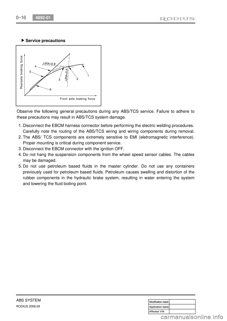
Service precautions ▶
Observe the following general precautions during any ABS/TCS service. Failure to adhere to
these precautions may result in ABS/TCS system damage.
Disconnect the EBCM harness connector before performing the electric welding procedures.
Carefully note the routing of the ABS/TCS wiring and wiring components during removal.
The ABS/ TCS components are extremely sensitive to EMI (eletromagnetic interference).
Proper mounting is critical during component service.
Disconnect the EBCM connector with the ignition OFF.
Do not hang the suspension components from the wheel speed sensor cables. The cables
may be damaged.
Do not use petroleum based fluids in the master cylinder. Do not use any containers
previously used for petroleum based fluids. Petroleum causes swelling and distortion of the
rubber components in the hydraulic brake system, resulting in water entering the system
and lowering the fluid boiling point. 1.
2.
3.
4.
5.
Page 357 of 465
0-18
RODIUS 2006.09
4892-01
ABS SYSTEM
2) HYDRAULIC CIRCUIT DIAGRAM
(1) Hydraulic Circuit of ABS
The vehicle equipped only with the ABS controls the wheel’s braking force using three 3-
channel 4-sensor method. The front wheels that are the primary circuit of the brake system is
composed of two wheel speed sensors and two channel valves system with two inlet valves
and two outlet valves. The rear wheels that are the secondary circuit of the brake system is
composed of two wheel speed sensors, one inlet valve and one outlet valve. This system is
similar to the one from the previous model.
Page 361 of 465
0-22
RODIUS 2006.09
4892-01
ABS SYSTEM
Pumping
▶
ECU (Including Solenoid Valves ? ESP Equipped Model)
▶
ECU lower cover)
▶
When the cam pushes the left plunger
during motor operation, the system pressure
is generated in the left cylinder. At this time,
the right plunger is expanded by spring force
and the expanded volume of the right
cylinder draws the brake fluid.
HECU controls the hydraulic valves by
supplying or cutting off the voltage to
solenoid valves depending on the wheel
speed and other information from wheel
speed sensors.
The figure shown in left side is for ESP
ECU. There are two channels for front
wheels and one channel for rear wheels.
Each channel has one inlet and one outlet
valve, therefore,
there are six solenoid valves.
The electrical components are weak to
moisture. To protect ECU, GoreTex-based
plate is used at ECU lower cover. The vent
hall (arrow) allows air to ventilate but does
not allow moisture to penetrate.
Page 385 of 465

0-13
AIR CONDITIONING SYSTEM
RODIUS 2006.09
6810-20
4. SENSORS AND ACTUATORS
1) Sun Sensor
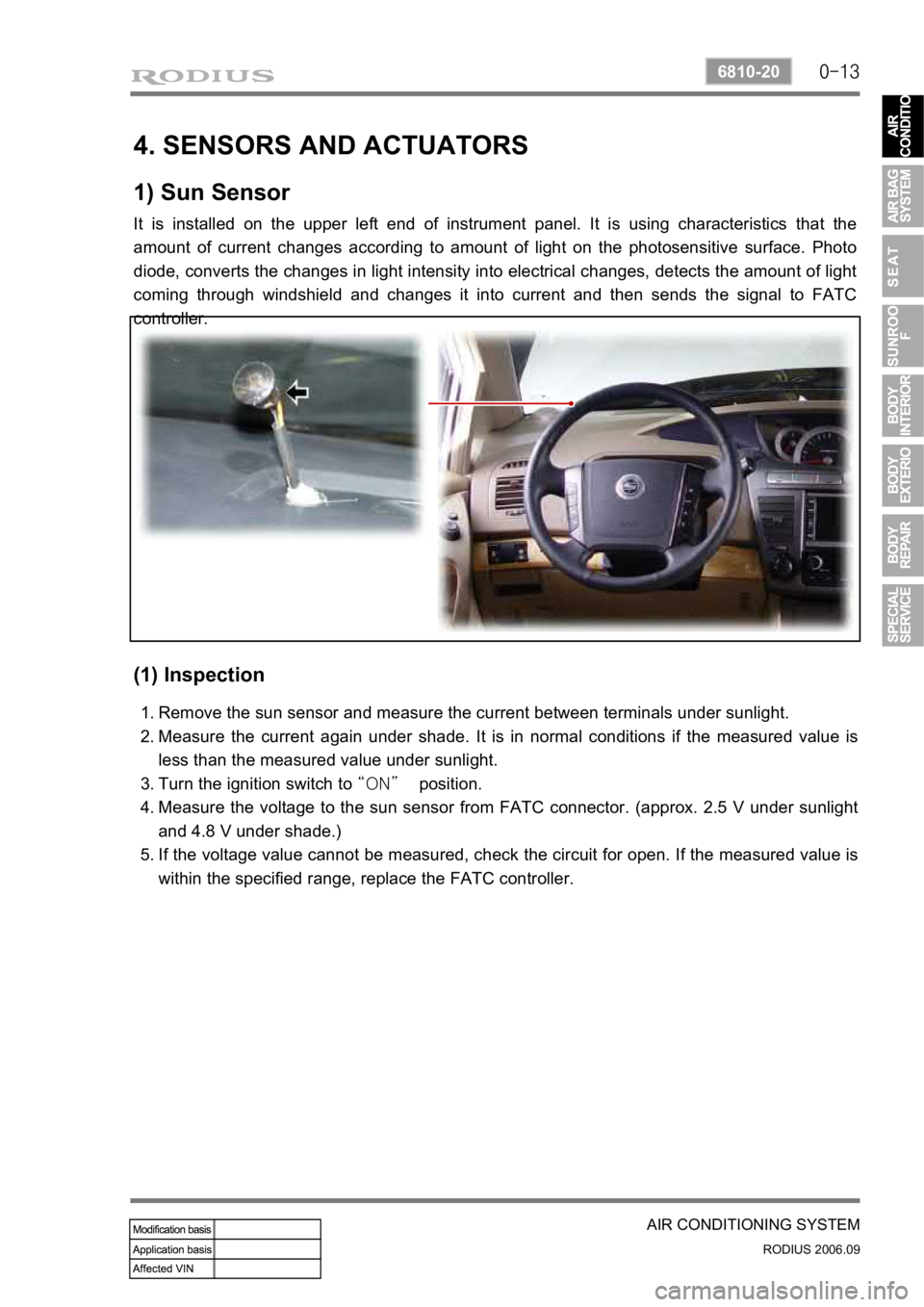
It is installed on the upper left end of instrument panel. It is using characteristics that the
amount of current changes according to amount of light on the photosensitive surface. Photo
diode, converts the changes in light intensity into electrical changes, detects the amount of light
coming through windshield and changes it into current and then sends the signal to FATC
controller.
(1) Inspection
Remove the sun sensor and measure the current between terminals under sunlight.
Measure the current again under shade. It is in normal conditions if the measured value is
less than the measured value under sunlight.
Turn the ignition switch to “ON” position.
Measure the voltage to the sun sensor from FATC connector. (approx. 2.5 V under sunlight
and 4.8 V under shade.)
If the voltage value cannot be measured, check the circuit for open. If the measured value is
within the specified range, replace the FATC controller. 1.
2.
3.
4.
5.
Page 386 of 465
0-14
RODIUS 2006.09
6810-20
AIR CONDITIONING SYSTEM
2) Active Incar/Humidity Sensor (AIH Sensor)
The AIH sensor is installed at the driver side instrument panel undercover. It is a sensor that
detects interior temperature and humidity.
(1) Location
(2) Functions
Interior temperature sensor
▶
This sensor is a negative temperature coefficient (NTC) thermistor and detects the interio
r
temperature with air coming from senor hole and then sends the voltage value according to the
changed resistance to FATC controller.
Humidity sensor
▶
This sensor detects the interior humidity with humidity cell and then sends the voltage value
according to the changed humidity to FATC controller.
Humidity
sensor
Active incar sensor
(interior temperature
sensor)
Page 387 of 465
0-15
AIR CONDITIONING SYSTEM
RODIUS 2006.09
6810-20
(3) Inspection
If the active incar sensor defect code (DTC 1) and the humidity sensor defect code (DTC 10)
are set, check as below:
Air conditioner controller
Air conditioner controller connector (based on wiring) AIH sensor (based on sensor)
Active incar sensor
▶
Remove the integrated AIH sensor and measure the resistance between terminal No. 5 and
6 on the sensor connector. (standard: approx. 25°C, 2.2 kΩ)
If the measured value is out of the specified range, replace the AIH sensor. If the measured
values are within the specified range, check as below.
Turn the ignition switch to ON position and measure the voltage to active incar sensor from
the FATC controller connector. (standard: approx. 2 V at 25°C)
If the voltage value cannot be measured, check the circuit for open. If the measured value is
within the specified range, replace the FATC controller.
1.
2.
3.
4.
Page 388 of 465
0-16
RODIUS 2006.09
6810-20
AIR CONDITIONING SYSTEM
Humidity sensor ▶
Apply 5 V to terminal No. 1 and 3 on the humidity sensor connector.
Connect the positive (+) probe of a tester on No. 2 terminal and the negative (-) probe on
No. 3 terminal, and measure the output voltage while the voltage is applied.
(output voltage: approx. 0.8 ~ 3.4 V)
Check whether the output voltage is changed when blowing into the inlet of the sensor. I
f
there is a voltage change, the sensor is in normal condition. However, if the voltage is not
changed, replace the humidity sensor.
In addition, if the output voltage is extremely high or low even in the specified range, replace
the humidity sensor. 1.
2.
3.
4.