Page 244 of 465

0-8
RODIUS 2006.09
8610-11
RAIN SENSOR
4) Washer Coupled Wiper Function
Check the washer coupled wiper operation by pressing the washer switch.
5) Irregular Operations (Abrupt Operations)
6) Self Diagnosis
Position the wiper switch to “AUTO” position and rotate the variable resistance knob from
“FAST” toward “SLOW” by one step.
At this moment, check if the wiper operates one cycle.
The wiper operates when the windshield glass is excessively worn or scratched, the windshield
glass is not cleared wiped due to using worn wiper blade or different wiper blade, or the rain
sensor is not improperly installed.Check the sensor for coming off.
Check the rain sensor cover installation.
Check that the customer is familiar to how to control the wiper sensitivity. -
-
-
If the wiper blade cannot wipe the glass uniformly and clearly, the irregular operations could be
occurred. And, the wiper blade should be replaced with new one with same specifications. Check that the customer can select the sensitivity by selecting the variable resistance value
(stage 1 to stage 5), that is, the wiper sensitivity control value. And, also check whether the
sensitivity is selected to the highest value of FAST (stage 5).
Check the wiper blade for wear. -
▶Poor sensing
▶Poor sensor
Rotate the variable resistance knob toward “SLOW” by 2 more steps. At this moment,
check if the wiper operates one cycle.
The wiper operates when the sensor is defective.
Page 245 of 465
0-9
RAIN SENSOR
RODIUS 2006.09
8610-11
5. DIAGNOSIS PROCEDURES
Page 246 of 465
0-10
RODIUS 2006.09
8610-11
RAIN SENSOR
6. RAIN SENSOR RELATED CIRCUIT
The rain sensor has one connector with 4 pins and each pin has following function as shown in
the circuit diagram.
However, in this vehicle, the terminal No. 1 and No. 2 are for communications between STICS
and the rain sensor; the No. 1 terminal sends the detected value from the rain sensor to STICS
then the STICS drives wiper motor.
to the rain sensor to recognize whether it is actual rain or it is in rain sensing wiper operation
mode.
No.2 terminal sends the wiper and washer operation information such as
washer operation mode,
MIST mode, or
AUTO wiper position -
-
-
Page 252 of 465
0-3
PARKING AID SYSTEM
RODIUS 2006.09
8790-04
8790-04PARKING ASSISTANCE SYSTEM
1. COMPONENT SPECIFICATIONS OF PARKING AID
SYSTEM
The parking aid system emits the supersonic wave signals from the sensors on the rear bumper
with a specific interval and detects the reflected signals from obstacles while the gear selecto
r
lever is in “R” position.
The number of displaying bars is decreased and the alarm interval becomes faster as the
obstacle approaches. This supplementary system is to secure the safety distance for parking.
Parking aid unit
Detecting type: Super sonic wave
Detecting distance: 25 ~ 120 cm
(distance between sensor and obstacle)
1)
Parking aid sensor
- Type: Piezo ceramic element
- Frequency: 40 KHz ± 2 KHz
- Detecting range (13.5 V)
* Horizontal: Min. 20° at 110 ± 5 cm Min. 1 00° at 50 ± 5 cm
* Vertical: Min. 20° at 110 ± 5 cm Min. 60° at 50 ± 5 cm
2)
Page 254 of 465
0-5
PARKING AID SYSTEM
RODIUS 2006.09
8790-04
Multi-meter
Front monitor ICM box
Even in other modes, it is changed to the parking aid
screen when moving the gear selector lever into
“R” position.
When moving the gear selector lever into “R”
position
while watching DVD or VCD, the rearview appears on
the front monitor.
When moving the gear selector lever into “R”
position, the alarm buzzer in ICM box sounds (installed
at bottom of STICS).
Parking aid sensor(Rear bumper)
The three parking aid sensors send the distance data
between rear bumper and obstacle to PAS unit.
Rearview camera
The rearview camera sends the rearview to the monitor
by using wide angle lens.
PAS unit
It is a control unit for the parking aid system (PAS) and
transmits the signals from sensors to multimeter and
buzzer.(installed in tuner/amplifier bracket)
Page 255 of 465
0-6
RODIUS 2006.09
8790-04
PARKING AID SYSTEM
The inside of the ICM BOX The outside of the ICM BOX
2. COMPONENTS OF PARKING AID SYSTEM(PAS)
1) parking AID SYSTEM COMPOSITION
Multi-meter Rear center obstacles
Rear right sensor
Rear right obstacles Rear left obstacles
Parking aid buzzer Rear left sensor
Rear center sensor
Page 256 of 465
0-7
PARKING AID SYSTEM
RODIUS 2006.09
8790-04
PAS UNIT The message on MULTI-METER
Center sensor
This unit controls the parking aid system. One of 3 LEDs comes on when the corresponding
parking aid sensor is defective and shows below message on multi-meter.
Amplifier withbuilt-in DSP
Navigation unit
Tuner
Right sensor Left sensor
Page 257 of 465

0-8
RODIUS 2006.09
8790-04
PARKING AID SYSTEM
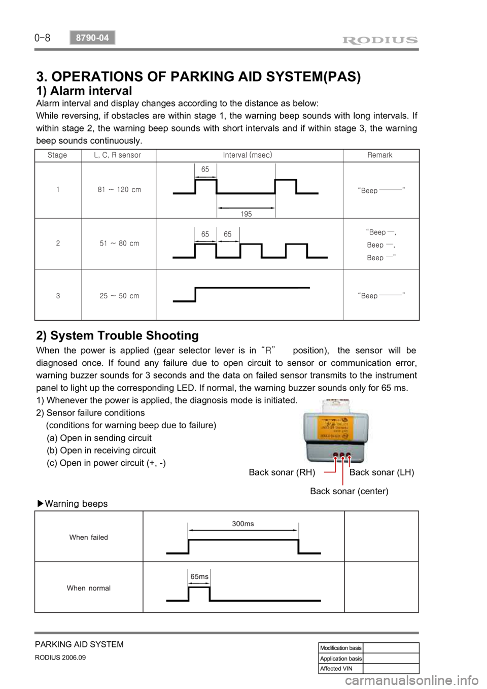
3. OPERATIONS OF PARKING AID SYSTEM(PAS)
1) Alarm interval
Alarm interval and display changes according to the distance as below:
While reversing, if obstacles are within stage 1, the warning beep sounds with long intervals. I
f
within stage 2, the warning beep sounds with short intervals and if within stage 3, the warning
beep sounds continuously.
2) System Trouble Shooting
When the power is applied (gear selector lever is in “R” position), the sensor will be
diagnosed once. If found any failure due to open circuit to sensor or communication error,
warning buzzer sounds for 3 seconds and the data on failed sensor transmits to the instrument
panel to light up the corresponding LED. If normal, the warning buzzer sounds only for 65 ms.
1) Whenever the power is applied, the diagnosis mode is initiated.
2) Sensor failure conditions
(conditions for warning beep due to failure)
(a) Open in sending circuit
(b) Open in receiving circuit
(c) Open in power circuit (+, -)
▶Warning beepsBack sonar (RH)
Back sonar (center)Back sonar (LH)