2007 NISSAN TIIDA Engine Control
[x] Cancel search: Engine ControlPage 1154 of 5883
![NISSAN TIIDA 2007 Service Repair Manual BCM (BODY CONTROL MODULE)
DLK-565
< ECU DIAGNOSIS >[WITHOUT I-KEY & SUPER LOCK]
C
D
E
F
G
H
I
J
L
MA
B
DLK
N
O
P
TURN SIGNAL LAMP CONTROL
BCM detects the turn signal lamp circuit status from the termi NISSAN TIIDA 2007 Service Repair Manual BCM (BODY CONTROL MODULE)
DLK-565
< ECU DIAGNOSIS >[WITHOUT I-KEY & SUPER LOCK]
C
D
E
F
G
H
I
J
L
MA
B
DLK
N
O
P
TURN SIGNAL LAMP CONTROL
BCM detects the turn signal lamp circuit status from the termi](/manual-img/5/57395/w960_57395-1153.png)
BCM (BODY CONTROL MODULE)
DLK-565
< ECU DIAGNOSIS >[WITHOUT I-KEY & SUPER LOCK]
C
D
E
F
G
H
I
J
L
MA
B
DLK
N
O
P
TURN SIGNAL LAMP CONTROL
BCM detects the turn signal lamp circuit status from the terminal voltage.
BCM increases the turn signal lamp blinking speed if the bulb or harness open is detected with the turn signal
lamp operating.
NOTE:
The blinking speed is normal while activating the hazard warning lamp.
DTC Inspection Priority ChartINFOID:0000000001397105
DTC IndexINFOID:0000000001397106
NOTE:
Details of time display
CRNT: Displays when there is a malfunction now or after returning to the normal condition until turning igni-
tion switch OFF → ON again.
PAST: Displays when there is a malfunction that is detected in the past and stored.
1 - 39: Displayed if any previous malfunction is present when current condition is normal. It increases like 1
→ 2 → 3...38 → 39 after returning to the normal condition whenever ignition switch OFF → ON. The counter
remains at 39 even if the number of cycles exceeds it. It is counted from 1 again when turning ignition switch
OFF → ON after returning to the normal condition if the malfunction is detected again.
Display contents of CONSULT Fail-safe Cancellation
B2190: NATS ANTENNA AMP Inhibits engine cranking
Fuel cut (ECM)Erase DTC
B2191: DIFFERENCE OF KEY Inhibits engine cranking
Fuel cut (ECM)Erase DTC
B2192: ID DISCORD BCM-ECM Fuel cut (ECM) Erase DTC
B2193: CHAIN OF BCM-ECM Fuel cut (ECM) Erase DTC
B2194: DISCORD BCM-I-KEY Inhibits engine cranking
Fuel cut (ECM)Erase DTC
B2195: ANTI SCANNING Inhibits engine cranking
Fuel cut (ECM)Erase DTC
B2196: DONGLE NG Inhibits engine cranking
Fuel cut (ECM)Erase DTC
Priority DTC
1 U1000: CAN COMM CIRCUIT
U1010: CONTROL UNIT (CAN)
2 B2190: NATS ANTENNA AMP
B2191: DIFFERNCE OF KEY
B2192: ID DISCORD BCM-ECM
B2193: CHAIN OF BCM-ECM
B2194: DISCORD BCM-I-KEY
B2195: ANTI SCANNING
B2196: DONGLE NG
CONSULT display TIME Fail-safe Refer to
No DTC is detected.
further testing
may be required.—— — —
U1000: CAN COMM CIRCUIT 0 1 - 39 —XX-XX, "*****"
U1010: CONTROL UNIT (CAN) 0 1 - 39 —XX-XX, "*****"
B2190: NATS ANTENNA AMP CRNT PAST×XX-XX, "*****"
B2191: DIFFERENCE OF KEY CRNT PAST×XX-XX, "*****"
B2192: ID DISCORD BCM-ECM CRNT PAST×XX-XX, "*****"
Page 1176 of 5883
![NISSAN TIIDA 2007 Service Repair Manual HOOD
DLK-587
< REMOVAL AND INSTALLATION >[WITHOUT I-KEY & SUPER LOCK]
C
D
E
F
G
H
I
J
L
MA
B
DLK
N
O
P
5. Remove hood opener on bottom left of instrument panel, and
then remove hood lock cable.
6. Rem NISSAN TIIDA 2007 Service Repair Manual HOOD
DLK-587
< REMOVAL AND INSTALLATION >[WITHOUT I-KEY & SUPER LOCK]
C
D
E
F
G
H
I
J
L
MA
B
DLK
N
O
P
5. Remove hood opener on bottom left of instrument panel, and
then remove hood lock cable.
6. Rem](/manual-img/5/57395/w960_57395-1175.png)
HOOD
DLK-587
< REMOVAL AND INSTALLATION >[WITHOUT I-KEY & SUPER LOCK]
C
D
E
F
G
H
I
J
L
MA
B
DLK
N
O
P
5. Remove hood opener on bottom left of instrument panel, and
then remove hood lock cable.
6. Remove grommet on lower dashboard, and pull out hood lock
cable from passenger room side.
CAUTION:
While pulling the cable, be careful not to damage (peel)
hood opener cable outer surface on edges of body through
hole.
INSTALLATION
Installation is in the reverse order of removal.
Perform hood fitting adjustment. Refer to DLK-583, "
Fitting Adjustment".
Hood Lock Reinforcement
When installing hood lock reinforcement, loosen hood bolts, and
then tighten bolts in the order as shown.
Hood Lock Cable
1. Pull the hood lock cable through the panel hole to the engine compartment.
CAUTION:
Be careful not to bend the cable too much, keeping the
radius 100 mm (3.94 in) or more.
2. Check that the cable is not offset from the positioning grommet,
and push the grommet into the panel hole securely.
3. Apply the sealant around the grommet (at * mark).
4. Install cable securely to lock.
5. After installing, check hood lock adjustment and hood opener
operation.
Hood Lock Control InspectionINFOID:0000000001732038
CAUTION:
If the hood lock cable is bent or deformed, replace it.
LIIA2667E
23.6 N·m (2.4 kg-m, 17 ft-lb)
PIIB6513E
PIIB5801E
PIIB6537E
Page 1305 of 5883
![NISSAN TIIDA 2007 Service Repair Manual DLK-716
< ECU DIAGNOSIS >[WITHOUT I-KEY, WITH SUPER LOCK]
BCM (BODY CONTROL MODULE)
TURN SIGNAL LAMP CONTROL
BCM detects the turn signal lamp circuit status from the terminal voltage.
BCM increases th NISSAN TIIDA 2007 Service Repair Manual DLK-716
< ECU DIAGNOSIS >[WITHOUT I-KEY, WITH SUPER LOCK]
BCM (BODY CONTROL MODULE)
TURN SIGNAL LAMP CONTROL
BCM detects the turn signal lamp circuit status from the terminal voltage.
BCM increases th](/manual-img/5/57395/w960_57395-1304.png)
DLK-716
< ECU DIAGNOSIS >[WITHOUT I-KEY, WITH SUPER LOCK]
BCM (BODY CONTROL MODULE)
TURN SIGNAL LAMP CONTROL
BCM detects the turn signal lamp circuit status from the terminal voltage.
BCM increases the turn signal lamp blinking speed if the bulb or harness open is detected with the turn signal
lamp operating.
NOTE:
The blinking speed is normal while activating the hazard warning lamp.
DTC Inspection Priority ChartINFOID:0000000001397330
DTC IndexINFOID:0000000001397331
NOTE:
Details of time display
CRNT: Displays when there is a malfunction now or after returning to the normal condition until turning igni-
tion switch OFF → ON again.
PAST: Displays when there is a malfunction that is detected in the past and stored.
1 - 39: Displayed if any previous malfunction is present when current condition is normal. It increases like 1
→ 2 → 3...38 → 39 after returning to the normal condition whenever ignition switch OFF → ON. The counter
remains at 39 even if the number of cycles exceeds it. It is counted from 1 again when turning ignition switch
OFF → ON after returning to the normal condition if the malfunction is detected again.
Display contents of CONSULT Fail-safe Cancellation
B2190: NATS ANTENNA AMP Inhibits engine cranking
Fuel cut (ECM)Erase DTC
B2191: DIFFERENCE OF KEY Inhibits engine cranking
Fuel cut (ECM)Erase DTC
B2192: ID DISCORD BCM-ECM Fuel cut (ECM) Erase DTC
B2193: CHAIN OF BCM-ECM Fuel cut (ECM) Erase DTC
B2194: DISCORD BCM-I-KEY Inhibits engine cranking
Fuel cut (ECM)Erase DTC
B2195: ANTI SCANNING Inhibits engine cranking
Fuel cut (ECM)Erase DTC
B2196: DONGLE NG Inhibits engine cranking
Fuel cut (ECM)Erase DTC
Priority DTC
1 U1000: CAN COMM CIRCUIT
U1010: CONTROL UNIT (CAN)
2 B2190: NATS ANTENNA AMP
B2191: DIFFERNCE OF KEY
B2192: ID DISCORD BCM-ECM
B2193: CHAIN OF BCM-ECM
B2194: DISCORD BCM-I-KEY
B2195: ANTI SCANNING
B2196: DONGLE NG
CONSULT display TIME Fail-safe Refer to
No DTC is detected.
further testing
may be required.—— — —
U1000: CAN COMM CIRCUIT 0 1 - 39 —XX-XX, "*****"
U1010: CONTROL UNIT (CAN) 0 1 - 39 —XX-XX, "*****"
B2190: NATS ANTENNA AMP CRNT PAST×XX-XX, "*****"
B2191: DIFFERENCE OF KEY CRNT PAST×XX-XX, "*****"
B2192: ID DISCORD BCM-ECM CRNT PAST×XX-XX, "*****"
Page 1327 of 5883
![NISSAN TIIDA 2007 Service Repair Manual DLK-738
< REMOVAL AND INSTALLATION >[WITHOUT I-KEY, WITH SUPER LOCK]
HOOD
5. Remove hood opener on bottom left of instrument panel, and
then remove hood lock cable.
6. Remove grommet on lower dashboar NISSAN TIIDA 2007 Service Repair Manual DLK-738
< REMOVAL AND INSTALLATION >[WITHOUT I-KEY, WITH SUPER LOCK]
HOOD
5. Remove hood opener on bottom left of instrument panel, and
then remove hood lock cable.
6. Remove grommet on lower dashboar](/manual-img/5/57395/w960_57395-1326.png)
DLK-738
< REMOVAL AND INSTALLATION >[WITHOUT I-KEY, WITH SUPER LOCK]
HOOD
5. Remove hood opener on bottom left of instrument panel, and
then remove hood lock cable.
6. Remove grommet on lower dashboard, and pull out hood lock
cable from passenger room side.
CAUTION:
While pulling the cable, be careful not to damage (peel)
hood opener cable outer surface on edges of body through
hole.
INSTALLATION
Installation is in the reverse order of removal.
Perform hood fitting adjustment. Refer to DLK-734, "
Fitting Adjustment".
Hood Lock Reinforcement
When installing hood lock reinforcement, loosen hood bolts, and
then tighten bolts in the order as shown.
Hood Lock Cable
1. Pull the hood lock cable through the panel hole to the engine compartment.
CAUTION:
Be careful not to bend the cable too much, keeping the
radius 100 mm (3.94 in) or more.
2. Check that the cable is not offset from the positioning grommet,
and push the grommet into the panel hole securely.
3. Apply the sealant around the grommet (at * mark).
4. Install cable securely to lock.
5. After installing, check hood lock adjustment and hood opener
operation.
Hood Lock Control InspectionINFOID:0000000001732056
CAUTION:
If the hood lock cable is bent or deformed, replace it.
LIIA2667E
23.6 N·m (2.4 kg-m, 17 ft-lb)
PIIB6513E
PIIB5801E
PIIB6537E
Page 1350 of 5883

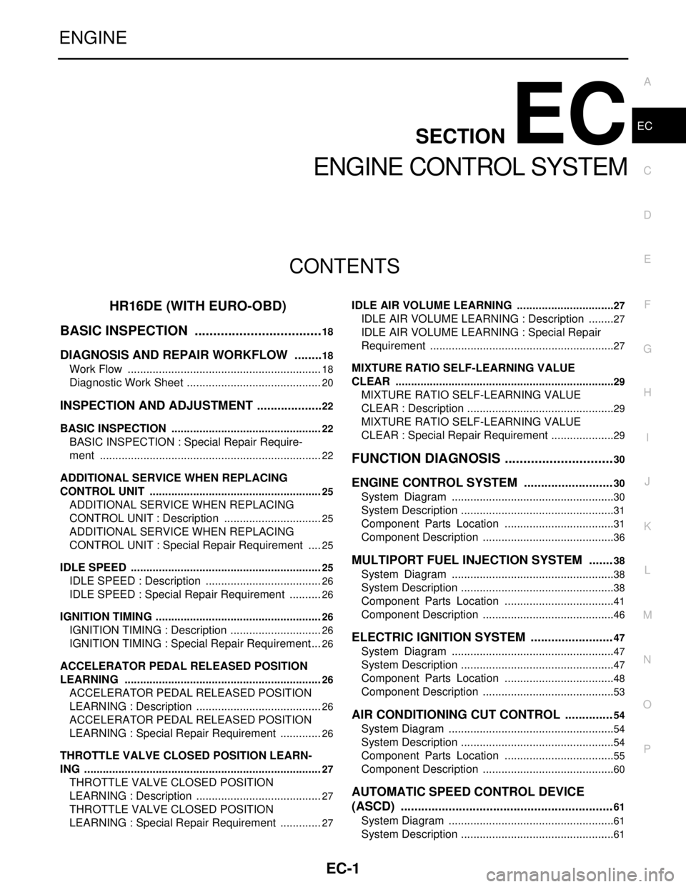
EC-1
ENGINE
C
D
E
F
G
H
I
J
K
L
M
SECTION EC
A
EC
N
O
P
CONTENTS
ENGINE CONTROL SYSTEM
HR16DE (WITH EURO-OBD)
BASIC INSPECTION ...................................
18
DIAGNOSIS AND REPAIR WORKFLOW .........18
Work Flow ...............................................................18
Diagnostic Work Sheet ............................................20
INSPECTION AND ADJUSTMENT ....................22
BASIC INSPECTION .................................................22
BASIC INSPECTION : Special Repair Require-
ment ........................................................................
22
ADDITIONAL SERVICE WHEN REPLACING
CONTROL UNIT ........................................................
25
ADDITIONAL SERVICE WHEN REPLACING
CONTROL UNIT : Description ................................
25
ADDITIONAL SERVICE WHEN REPLACING
CONTROL UNIT : Special Repair Requirement .....
25
IDLE SPEED ..............................................................25
IDLE SPEED : Description ......................................26
IDLE SPEED : Special Repair Requirement ...........26
IGNITION TIMING ......................................................26
IGNITION TIMING : Description ..............................26
IGNITION TIMING : Special Repair Requirement ....26
ACCELERATOR PEDAL RELEASED POSITION
LEARNING ................................................................
26
ACCELERATOR PEDAL RELEASED POSITION
LEARNING : Description .........................................
26
ACCELERATOR PEDAL RELEASED POSITION
LEARNING : Special Repair Requirement ..............
26
THROTTLE VALVE CLOSED POSITION LEARN-
ING .............................................................................
27
THROTTLE VALVE CLOSED POSITION
LEARNING : Description .........................................
27
THROTTLE VALVE CLOSED POSITION
LEARNING : Special Repair Requirement ..............
27
IDLE AIR VOLUME LEARNING ................................27
IDLE AIR VOLUME LEARNING : Description .........27
IDLE AIR VOLUME LEARNING : Special Repair
Requirement ............................................................
27
MIXTURE RATIO SELF-LEARNING VALUE
CLEAR .......................................................................
29
MIXTURE RATIO SELF-LEARNING VALUE
CLEAR : Description ................................................
29
MIXTURE RATIO SELF-LEARNING VALUE
CLEAR : Special Repair Requirement .....................
29
FUNCTION DIAGNOSIS ..............................30
ENGINE CONTROL SYSTEM ..........................30
System Diagram .....................................................30
System Description ..................................................31
Component Parts Location ....................................31
Component Description ...........................................36
MULTIPORT FUEL INJECTION SYSTEM .......38
System Diagram .....................................................38
System Description ..................................................38
Component Parts Location ....................................41
Component Description ...........................................46
ELECTRIC IGNITION SYSTEM ........................47
System Diagram .....................................................47
System Description ..................................................47
Component Parts Location ....................................48
Component Description ...........................................53
AIR CONDITIONING CUT CONTROL ..............54
System Diagram ......................................................54
System Description ..................................................54
Component Parts Location ....................................55
Component Description ...........................................60
AUTOMATIC SPEED CONTROL DEVICE
(ASCD) ..............................................................
61
System Diagram ......................................................61
System Description ..................................................61
Page 1354 of 5883

EC-5
C
D
E
F
G
H
I
J
K
L
M
ECA
N
O
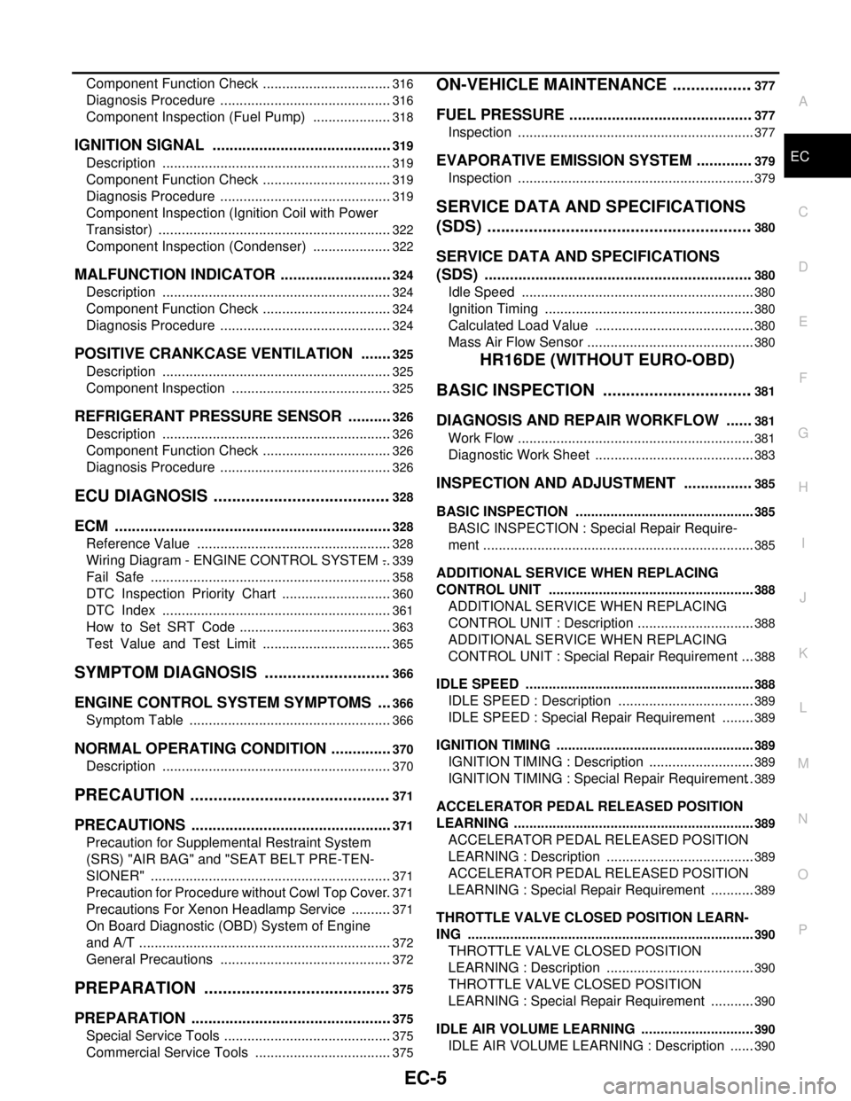
P Component Function Check ..................................
316
Diagnosis Procedure .............................................316
Component Inspection (Fuel Pump) .....................318
IGNITION SIGNAL ...........................................319
Description ............................................................319
Component Function Check ..................................319
Diagnosis Procedure .............................................319
Component Inspection (Ignition Coil with Power
Transistor) .............................................................
322
Component Inspection (Condenser) .....................322
MALFUNCTION INDICATOR ...........................324
Description ............................................................324
Component Function Check ..................................324
Diagnosis Procedure .............................................324
POSITIVE CRANKCASE VENTILATION ........325
Description ............................................................325
Component Inspection ..........................................325
REFRIGERANT PRESSURE SENSOR ...........326
Description ............................................................326
Component Function Check ..................................326
Diagnosis Procedure .............................................326
ECU DIAGNOSIS .......................................328
ECM ..................................................................328
Reference Value ...................................................328
Wiring Diagram - ENGINE CONTROL SYSTEM - ..339
Fail Safe ...............................................................358
DTC Inspection Priority Chart .............................360
DTC Index ............................................................361
How to Set SRT Code ........................................363
Test Value and Test Limit ..................................365
SYMPTOM DIAGNOSIS ............................366
ENGINE CONTROL SYSTEM SYMPTOMS ....366
Symptom Table .....................................................366
NORMAL OPERATING CONDITION ...............370
Description ............................................................370
PRECAUTION ............................................371
PRECAUTIONS ................................................371
Precaution for Supplemental Restraint System
(SRS) "AIR BAG" and "SEAT BELT PRE-TEN-
SIONER" ...............................................................
371
Precaution for Procedure without Cowl Top Cover ..371
Precautions For Xenon Headlamp Service ...........371
On Board Diagnostic (OBD) System of Engine
and A/T ..................................................................
372
General Precautions .............................................372
PREPARATION .........................................375
PREPARATION ................................................375
Special Service Tools ............................................375
Commercial Service Tools ....................................375
ON-VEHICLE MAINTENANCE ..................377
FUEL PRESSURE ...........................................377
Inspection ..............................................................377
EVAPORATIVE EMISSION SYSTEM .............379
Inspection ..............................................................379
SERVICE DATA AND SPECIFICATIONS
(SDS) ..........................................................
380
SERVICE DATA AND SPECIFICATIONS
(SDS) ...............................................................
380
Idle Speed .............................................................380
Ignition Timing .......................................................380
Calculated Load Value ..........................................380
Mass Air Flow Sensor ............................................380
HR16DE (WITHOUT EURO-OBD)
BASIC INSPECTION .................................
381
DIAGNOSIS AND REPAIR WORKFLOW ......381
Work Flow ..............................................................381
Diagnostic Work Sheet ..........................................383
INSPECTION AND ADJUSTMENT ................385
BASIC INSPECTION ...............................................385
BASIC INSPECTION : Special Repair Require-
ment .......................................................................
385
ADDITIONAL SERVICE WHEN REPLACING
CONTROL UNIT ......................................................
388
ADDITIONAL SERVICE WHEN REPLACING
CONTROL UNIT : Description ...............................
388
ADDITIONAL SERVICE WHEN REPLACING
CONTROL UNIT : Special Repair Requirement ....
388
IDLE SPEED ............................................................388
IDLE SPEED : Description ....................................389
IDLE SPEED : Special Repair Requirement .........389
IGNITION TIMING ....................................................389
IGNITION TIMING : Description ............................389
IGNITION TIMING : Special Repair Requirement ..389
ACCELERATOR PEDAL RELEASED POSITION
LEARNING ...............................................................
389
ACCELERATOR PEDAL RELEASED POSITION
LEARNING : Description .......................................
389
ACCELERATOR PEDAL RELEASED POSITION
LEARNING : Special Repair Requirement ............
389
THROTTLE VALVE CLOSED POSITION LEARN-
ING ...........................................................................
390
THROTTLE VALVE CLOSED POSITION
LEARNING : Description .......................................
390
THROTTLE VALVE CLOSED POSITION
LEARNING : Special Repair Requirement ............
390
IDLE AIR VOLUME LEARNING ..............................390
IDLE AIR VOLUME LEARNING : Description .......390
Page 1355 of 5883

EC-6
IDLE AIR VOLUME LEARNING : Special Repair
Requirement ..........................................................
390
MIXTURE RATIO SELF-LEARNING VALUE
CLEAR .....................................................................
392
MIXTURE RATIO SELF-LEARNING VALUE
CLEAR : Description ..............................................
392
MIXTURE RATIO SELF-LEARNING VALUE
CLEAR : Special Repair Requirement ...................
392
FUNCTION DIAGNOSIS ............................393
ENGINE CONTROL SYSTEM .........................393
System Diagram ...................................................393
System Description ................................................394
Component Parts Location ..................................394
Component Description .........................................399
MULTIPORT FUEL INJECTION SYSTEM ......401
System Diagram ...................................................401
System Description ................................................401
Component Parts Location ..................................404
Component Description .........................................409
ELECTRIC IGNITION SYSTEM .......................410
System Diagram ...................................................410
System Description ................................................410
Component Parts Location ..................................411
Component Description .........................................416
AIR CONDITIONING CUT CONTROL ............417
System Diagram ....................................................417
System Description ................................................417
Component Parts Location ..................................418
Component Description .........................................423
AUTOMATIC SPEED CONTROL DEVICE
(ASCD) .............................................................
424
System Diagram ....................................................424
System Description ................................................424
Component Parts Location ..................................426
Component Description ........................................431
CAN COMMUNICATION .................................432
System Description ................................................432
COOLING FAN CONTROL .............................433
System Diagram ....................................................433
System Description ................................................433
Component Parts Location ..................................435
Component Description .........................................440
EVAPORATIVE EMISSION SYSTEM .............441
System Diagram ....................................................441
System Description ................................................443
Component Parts Location ..................................444
Component Description ........................................449
INTAKE VALVE TIMING CONTROL ...............450
System Diagram ....................................................450
System Description ................................................450
Component Parts Location ..................................451
Component Description ........................................456
DIAGNOSIS SYSTEM (ECM) ...........................457
Diagnosis Description ...........................................457
CONSULT-III Function ..........................................462
COMPONENT DIAGNOSIS ......................469
TROUBLE DIAGNOSIS - SPECIFICATION
VALUE ..............................................................
469
Description ............................................................469
Component Function Check .................................469
Diagnosis Procedure .............................................470
POWER SUPPLY AND GROUND CIRCUIT ....477
Diagnosis Procedure .............................................477
U1000, U1001 CAN COMM CIRCUIT ..............481
Description ............................................................481
DTC Logic .............................................................481
Diagnosis Procedure .............................................481
U1010 CONTROL UNIT (CAN) ........................482
Description ............................................................482
DTC Logic .............................................................482
Diagnosis Procedure .............................................482
P0011 IVT CONTROL ......................................483
DTC Logic .............................................................483
Component Function Check .................................484
Diagnosis Procedure .............................................484
Component Inspection ..........................................486
P0102, P0103 MAF SENSOR ..........................487
Description ............................................................487
DTC Logic .............................................................487
Diagnosis Procedure .............................................488
Component Inspection ..........................................489
P0117, P0118 ECT SENSOR ...........................492
Description ............................................................492
DTC Logic .............................................................492
Diagnosis Procedure .............................................493
Component Inspection ..........................................493
P0122, P0123 TP SENSOR ..............................495
Description ............................................................495
DTC Logic .............................................................495
Diagnosis Procedure .............................................495
Component Inspection ..........................................497
Special Repair Requirement .................................497
P0132 HO2S1 ...................................................498
Description ............................................................498
DTC Logic .............................................................498
Diagnosis Procedure .............................................499
Component Inspection ..........................................500
P0134 HO2S1 ...................................................502
Description ............................................................502
DTC Logic .............................................................502
Page 1356 of 5883

EC-7
C
D
E
F
G
H
I
J
K
L
M
ECA
N
O
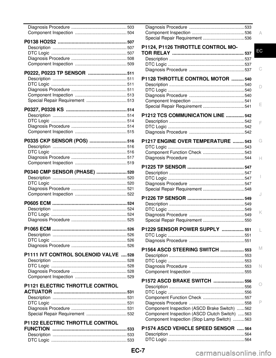
P Diagnosis Procedure .............................................
503
Component Inspection ..........................................504
P0138 HO2S2 ...................................................507
Description ............................................................507
DTC Logic .............................................................507
Diagnosis Procedure .............................................508
Component Inspection ..........................................509
P0222, P0223 TP SENSOR .............................511
Description ............................................................511
DTC Logic .............................................................511
Diagnosis Procedure .............................................511
Component Inspection ..........................................513
Special Repair Requirement .................................513
P0327, P0328 KS .............................................514
Description ............................................................514
DTC Logic .............................................................514
Diagnosis Procedure .............................................514
Component Inspection ..........................................515
P0335 CKP SENSOR (POS) ............................516
Description ............................................................516
DTC Logic .............................................................516
Diagnosis Procedure .............................................517
Component Inspection ..........................................519
P0340 CMP SENSOR (PHASE) .......................520
Description ............................................................520
DTC Logic .............................................................520
Diagnosis Procedure .............................................521
Component Inspection ..........................................522
P0605 ECM .......................................................524
Description ............................................................524
DTC Logic .............................................................524
Diagnosis Procedure .............................................525
P1065 ECM .......................................................526
Description ............................................................526
DTC Logic .............................................................526
Diagnosis Procedure .............................................526
P1111 IVT CONTROL SOLENOID VALVE .....528
Description ............................................................528
DTC Logic .............................................................528
Diagnosis Procedure .............................................528
Component Inspection ..........................................529
P1121 ELECTRIC THROTTLE CONTROL
ACTUATOR ......................................................
531
Description ............................................................531
DTC Logic .............................................................531
Diagnosis Procedure .............................................531
Special Repair Requirement .................................532
P1122 ELECTRIC THROTTLE CONTROL
FUNCTION .......................................................
533
Description ............................................................533
DTC Logic .............................................................533
Diagnosis Procedure .............................................533
Component Inspection ...........................................536
Special Repair Requirement ..................................536
P1124, P1126 THROTTLE CONTROL MO-
TOR RELAY ....................................................
537
Description .............................................................537
DTC Logic ..............................................................537
Diagnosis Procedure .............................................537
P1128 THROTTLE CONTROL MOTOR .........540
Description .............................................................540
DTC Logic ..............................................................540
Diagnosis Procedure .............................................540
Component Inspection ...........................................541
Special Repair Requirement ..................................541
P1212 TCS COMMUNICATION LINE .............542
Description .............................................................542
DTC Logic ..............................................................542
Diagnosis Procedure .............................................542
P1217 ENGINE OVER TEMPERATURE ........543
DTC Logic ..............................................................543
Component Function Check ..................................543
Diagnosis Procedure .............................................544
P1225 TP SENSOR .........................................547
Description .............................................................547
DTC Logic ..............................................................547
Diagnosis Procedure .............................................547
Special Repair Requirement ..................................548
P1226 TP SENSOR .........................................549
Description .............................................................549
DTC Logic ..............................................................549
Diagnosis Procedure .............................................549
Special Repair Requirement ..................................550
P1229 SENSOR POWER SUPPLY ................551
DTC Logic ..............................................................551
Diagnosis Procedure .............................................551
P1564 ASCD STEERING SWITCH .................553
Description .............................................................553
DTC Logic ..............................................................553
Diagnosis Procedure .............................................553
Component Inspection ...........................................555
P1572 ASCD BRAKE SWITCH ......................556
Description .............................................................556
DTC Logic ..............................................................556
Component Function Check ..................................557
Diagnosis Procedure .............................................558
Component Inspection (ASCD Brake Switch) .......562
Component Inspection (ASCD Clutch Switch) ......563
Component Inspection (Stop Lamp Switch) ..........563
P1574 ASCD VEHICLE SPEED SENSOR .....564
Description .............................................................564
DTC Logic ..............................................................564