Page 5824 of 5883
WW-22
< COMPONENT DIAGNOSIS >
FRONT WIPER AUTO STOP SIGNAL CIRCUIT
FRONT WIPER AUTO STOP SIGNAL CIRCUIT
Component Function CheckINFOID:0000000001366614
1. CHECK FRONT WIPER (AUTO STOP) SIGNAL CHECK
CONSULT-III DATA MONITOR
1. Select "FRONT WIPER STOP" of IPDM E/R data monitor item.
2. Operate the front wiper.
3. Check that "FR WIPER STOP" changes to "STOP P" and "ACT P" linked with the wiper operation.
Is the status of item normal?
YES >> Front wiper auto stop signal circuit is normal.
NO >> Refer to WW-22, "
Diagnosis Procedure".
Diagnosis ProcedureINFOID:0000000001366615
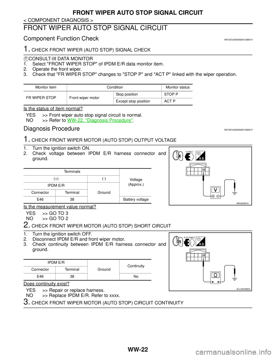
1. CHECK FRONT WIPER MOTOR (AUTO STOP) OUTPUT VOLTAGE
1. Turn the ignition switch ON.
2. Check voltage between IPDM E/R harness connector and
ground.
Is the measurement value normal?
YES >> GO TO 3
NO >> GO TO 2
2. CHECK FRONT WIPER MOTOR (AUTO STOP) SHORT CIRCUIT
1. Turn the ignition switch OFF.
2. Disconnect IPDM E/R and front wiper motor.
3. Check continuity between IPDM E/R harness connector and
ground.
Does continuity exist?
YES >> Repair or replace harness.
NO >> Replace IPDM E/R. Refer to xxxx.
3. CHECK FRONT WIPER MOTOR (AUTO STOP) CIRCUIT CONTINUITY
Monitor item Condition Monitor status
FR WIPER STOP Front wiper motorStop position STOP P
Except stop position ACT P
Te r m i n a l s
Voltage
(Approx.) (+) (-)
IPDM E/R
Ground Connector Terminal
E46 38 Battery voltage
WKIA5491E
IPDM E/R
GroundContinuity
Connector Terminal
E46 38 No
ALLIA0348ZZ
Page 5830 of 5883
WW-28
< COMPONENT DIAGNOSIS >
REAR WIPER MOTOR CIRCUIT
REAR WIPER MOTOR CIRCUIT
Component Function CheckINFOID:0000000001366621
1. CHECK REAR WIPER ON OPERATION
CONSULT-III ACTIVE TEST
1. Select "RR WIPER" of BCM active test item.
2. While operating the test item, check rear wiper operation.
Is rear wiper operation normal?
YES >> Rear wiper motor circuit is normal.
NO >> Refer to WW-28, "
Diagnosis Procedure".
Diagnosis ProcedureINFOID:0000000001366622
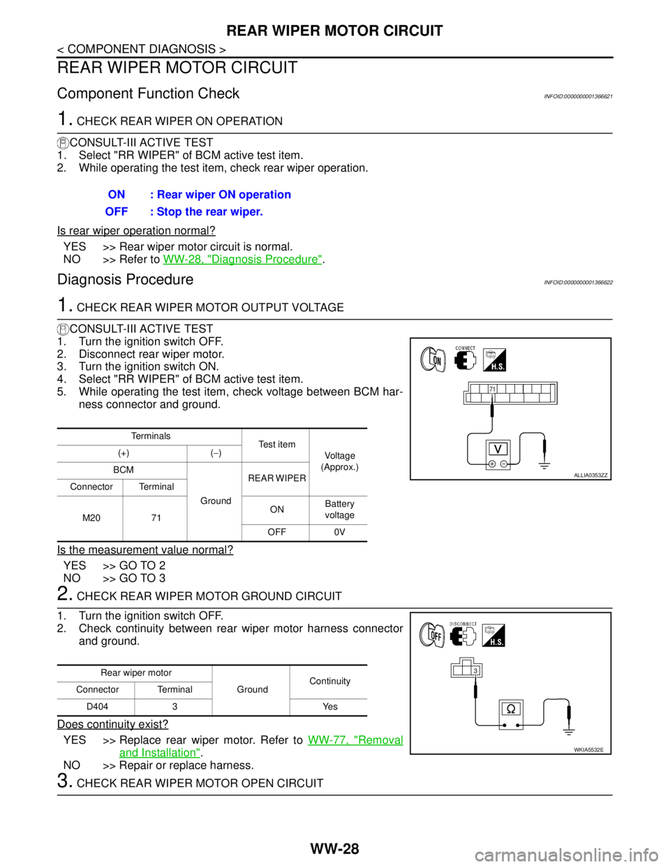
1. CHECK REAR WIPER MOTOR OUTPUT VOLTAGE
CONSULT-III ACTIVE TEST
1. Turn the ignition switch OFF.
2. Disconnect rear wiper motor.
3. Turn the ignition switch ON.
4. Select "RR WIPER" of BCM active test item.
5. While operating the test item, check voltage between BCM har-
ness connector and ground.
Is the measurement value normal?
YES >> GO TO 2
NO >> GO TO 3
2. CHECK REAR WIPER MOTOR GROUND CIRCUIT
1. Turn the ignition switch OFF.
2. Check continuity between rear wiper motor harness connector
and ground.
Does continuity exist?
YES >> Replace rear wiper motor. Refer to WW-77, "Removal
and Installation".
NO >> Repair or replace harness.
3. CHECK REAR WIPER MOTOR OPEN CIRCUIT ON : Rear wiper ON operation
OFF : Stop the rear wiper.
Te r m i n a l s
Te s t i t e m
Voltage
(Approx.) (+) (−)
BCM
GroundREAR WIPER
Connector Terminal
M20 71ONBattery
voltage
OFF 0V
ALLIA0353ZZ
Rear wiper motor
GroundContinuity
Connector Terminal
D404 3 Yes
WKIA5532E
Page 5832 of 5883
WW-30
< COMPONENT DIAGNOSIS >
REAR WIPER AUTO STOP SIGNAL CIRCUIT
REAR WIPER AUTO STOP SIGNAL CIRCUIT
Component Function CheckINFOID:0000000001366623
1.CHECK REAR WIPER (AUTO STOP) OPERATION
CONSULT-III DATA MONITOR
1. Select "WIPER" of BCM data monitor item.
2. Operate the rear wiper.
3. Check that "RR WIPER STOP" changes to "ON" and "OFF" linked with the wiper operation.
Is the status of item normal?
YES >> Rear wiper auto stop signal circuit is normal.
NO >> Refer to WW-30, "
Diagnosis Procedure".
Diagnosis ProcedureINFOID:0000000001366624
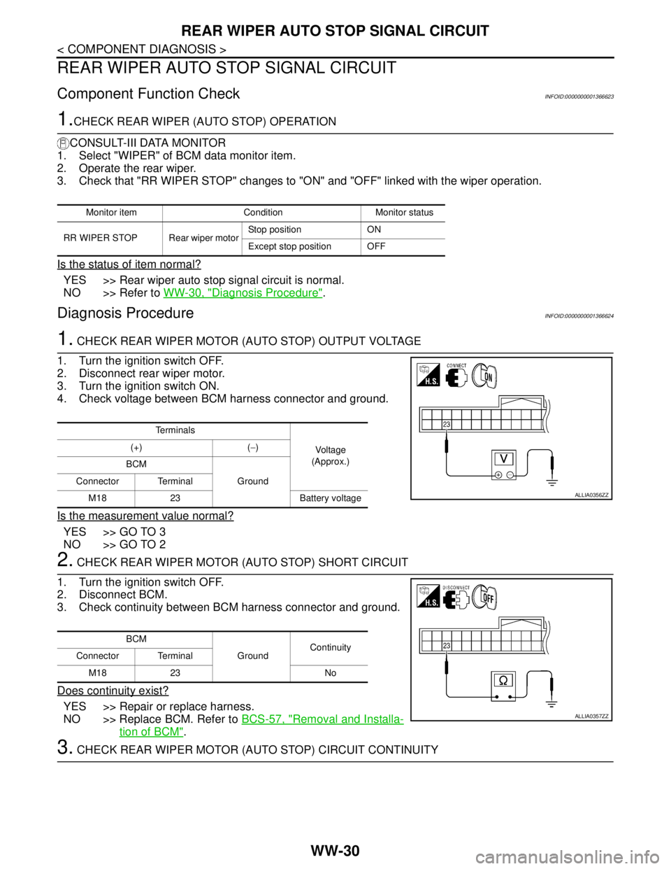
1. CHECK REAR WIPER MOTOR (AUTO STOP) OUTPUT VOLTAGE
1. Turn the ignition switch OFF.
2. Disconnect rear wiper motor.
3. Turn the ignition switch ON.
4. Check voltage between BCM harness connector and ground.
Is the measurement value normal?
YES >> GO TO 3
NO >> GO TO 2
2. CHECK REAR WIPER MOTOR (AUTO STOP) SHORT CIRCUIT
1. Turn the ignition switch OFF.
2. Disconnect BCM.
3. Check continuity between BCM harness connector and ground.
Does continuity exist?
YES >> Repair or replace harness.
NO >> Replace BCM. Refer to BCS-57, "
Removal and Installa-
tion of BCM".
3. CHECK REAR WIPER MOTOR (AUTO STOP) CIRCUIT CONTINUITY
Monitor item Condition Monitor status
RR WIPER STOP Rear wiper motorStop position ON
Except stop position OFF
Te r m i n a l s
Voltage
(Approx.) (+) (−)
BCM
Ground Connector Terminal
M18 23 Battery voltage
ALLIA0356ZZ
BCM
GroundContinuity
Connector Terminal
M18 23 No
ALLIA0357ZZ
Page 5834 of 5883
WW-32
< COMPONENT DIAGNOSIS >
HEADLAMP WASHER RELAY
HEADLAMP WASHER RELAY
Component InspectionINFOID:0000000001366625
1. CHECK HEADLAMP WASHER RELAY
1. Turn the ignition switch OFF.
2. Disconnect headlamp washer relay.
3. Apply battery voltage to headlamp washer relay between termi-
nals 1 and 2.
4. Check continuity of headlamp washer relay.
Does continuity exist?
YES >> Headlamp washer relay is normal.
NO >> Replace headlamp washer relay.
Headlamp washer relay Condition
Continuity
Terminal Voltage
35Apply Yes
Not Apply No
SEF145X
Page 5835 of 5883
HEADLAMP WASHER CIRCUIT
WW-33
< COMPONENT DIAGNOSIS >
C
D
E
F
G
H
I
J
K
MA
B
WW
N
O
P
HEADLAMP WASHER CIRCUIT
Component Function CheckINFOID:0000000001366626
1. CHECK HEADLAMP WASHER OPERATION
CONSULT-III ACTIVE TEST
1. Select "HEAD LAMP WASHER" of IPDM E/R active test item.
2. While operating the test item, check headlamp washer operation.
Is the headlamp washer operation normally?
YES >> Headlamp washer circuit is normal.
NO >> Refer to WW-33, "
Diagnosis Procedure".
Diagnosis ProcedureINFOID:0000000001366627
1. CHECK HEADLAMP WASHER FUSIBLE LINK
1. Turn the ignition switch OFF.
2. Check that the following fusible link is not blown.
Is the fusible link blown?
YES >> Replace the fusible link after repairing the applicable circuit.
NO >> GO TO 2
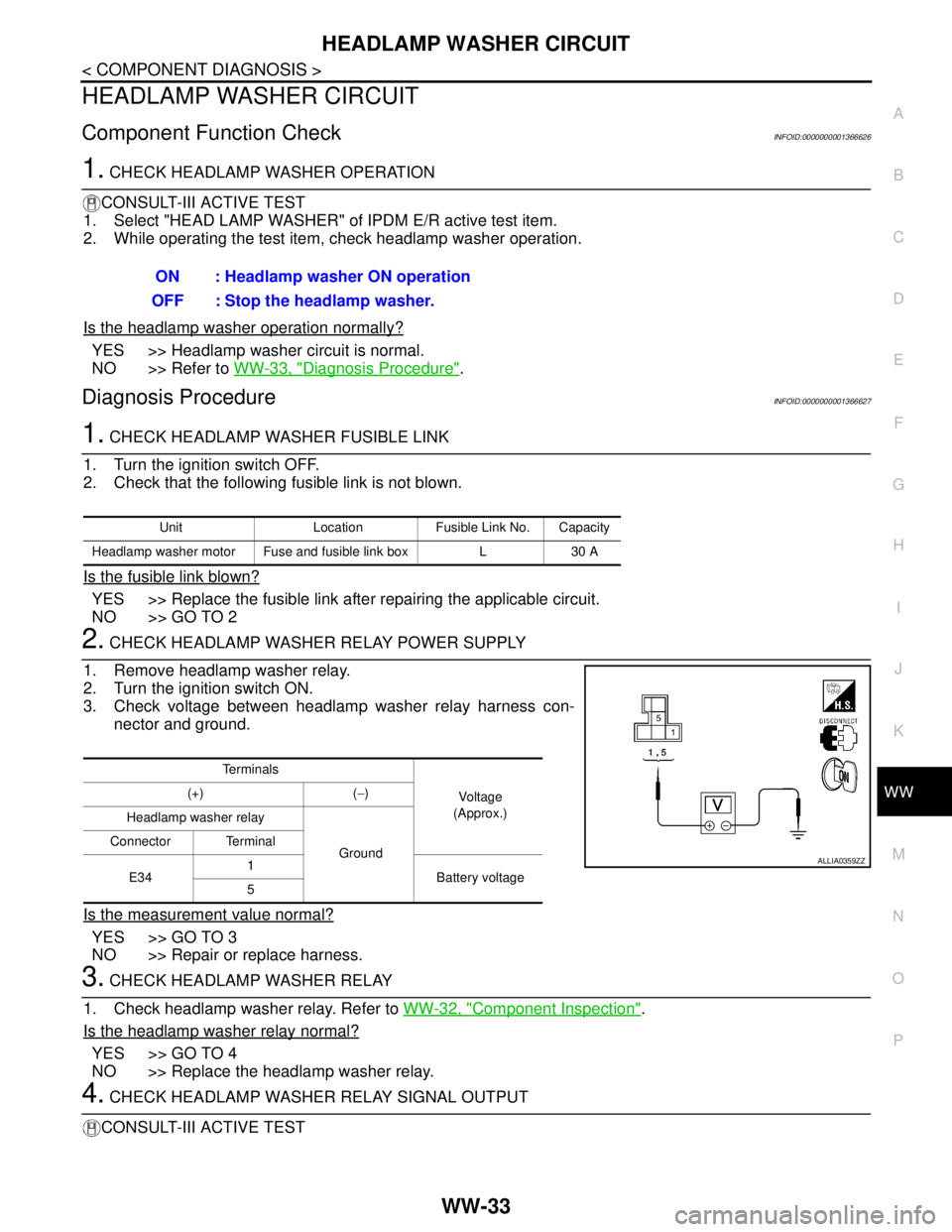
2. CHECK HEADLAMP WASHER RELAY POWER SUPPLY
1. Remove headlamp washer relay.
2. Turn the ignition switch ON.
3. Check voltage between headlamp washer relay harness con-
nector and ground.
Is the measurement value normal?
YES >> GO TO 3
NO >> Repair or replace harness.
3. CHECK HEADLAMP WASHER RELAY
1. Check headlamp washer relay. Refer to WW-32, "
Component Inspection".
Is the headlamp washer relay normal?
YES >> GO TO 4
NO >> Replace the headlamp washer relay.
4. CHECK HEADLAMP WASHER RELAY SIGNAL OUTPUT
CONSULT-III ACTIVE TESTON : Headlamp washer ON operation
OFF : Stop the headlamp washer.
Unit Location Fusible Link No. Capacity
Headlamp washer motor Fuse and fusible link box L 30 A
Te r m i n a l s
Vo l ta g e
(Approx.) (+) (−)
Headlamp washer relay
Ground Connector Terminal
E341
Battery voltage
5
ALLIA0359ZZ
Page 5836 of 5883
WW-34
< COMPONENT DIAGNOSIS >
HEADLAMP WASHER CIRCUIT
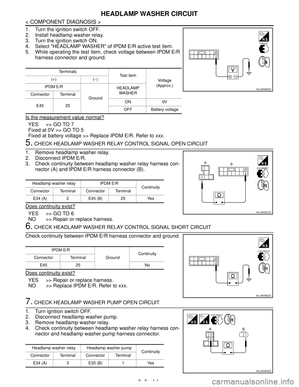
1. Turn the ignition switch OFF.
2. Install headlamp washer relay.
3. Turn the ignition switch ON.
4. Select "HEADLAMP WASHER" of IPDM E/R active test item.
5. While operating the test item, check voltage between IPDM E/R
harness connector and ground.
Is the measurement value normal?
YES >> GO TO 7
Fixed at 0V >> GO TO 5
Fixed at battery voltage >> Replace IPDM E/R. Refer to xxx.
5. CHECK HEADLAMP WASHER RELAY CONTROL SIGNAL OPEN CIRCUIT
1. Remove headlamp washer relay.
2. Disconnect IPDM E/R.
3. Check continuity between headlamp washer relay harness con-
nector (A) and IPDM E/R harness connector (B).
Does continuity exist?
YES >> GO TO 6
NO >> Repair or replace harness.
6. CHECK HEADLAMP WASHER RELAY CONTROL SIGNAL SHORT CIRCUIT
Check continuity between IPDM E/R harness connector and ground.
Does continuity exist?
YES >> Repair or replace harness.
NO >> Replace IPDM E/R. Refer to xxx.
7. CHECK HEADLAMP WASHER PUMP OPEN CIRCUIT
1. Turn ignition switch OFF.
2. Disconnect headlamp washer pump.
3. Remove headlamp washer relay.
4. Check continuity between headlamp washer relay harness con-
nector and headlamp washer pump harness connector.
Te r m i n a l s
Te s t i t e m
Vo l ta g e
(Approx.) (+) (−)
IPDM E/R
GroundHEADLAMP
WASHER
Connector Terminal
E45 25ON 0V
OFF Battery voltage
ALLIA0360ZZ
Headlamp washer relay IPDM E/R
Continuity
Connector Terminal Connector Terminal
E34 (A) 2 E45 (B) 25 Yes
ALLIA0361ZZ
IPDM E/R
GroundContinuity
Connector Terminal
E45 25 No
ALLIA0362ZZ
Headlamp washer relay Headlamp washer pump
Continuity
Connector Terminal Connector Terminal
E34 (A) 3 E35 (B) 1 Yes
ALLIA0363ZZ
Page 5861 of 5883
FRONT WIPER DOES NOT OPERATE
WW-59
< SYMPTOM DIAGNOSIS >
C
D
E
F
G
H
I
J
K
MA
B
WW
N
O
P
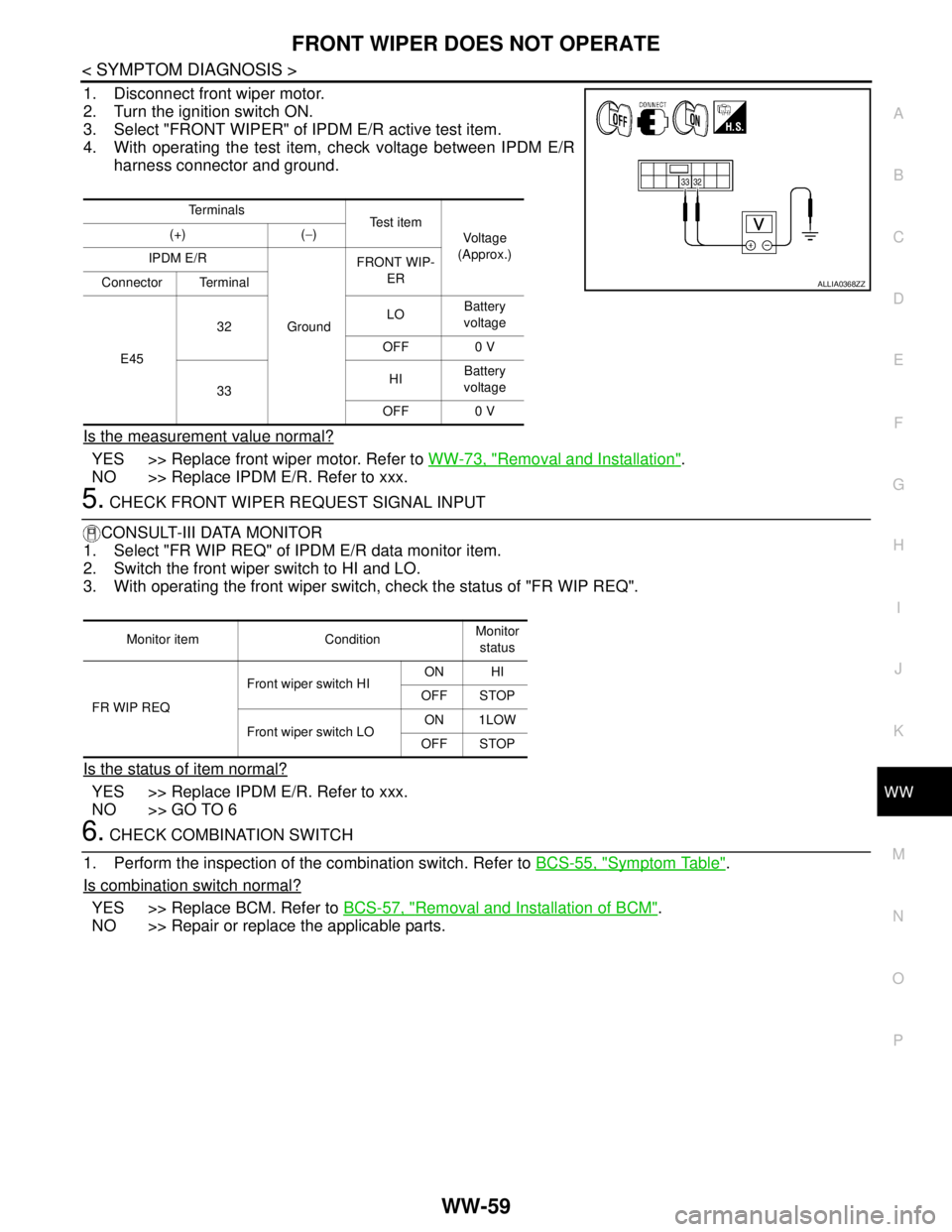
1. Disconnect front wiper motor.
2. Turn the ignition switch ON.
3. Select "FRONT WIPER" of IPDM E/R active test item.
4. With operating the test item, check voltage between IPDM E/R
harness connector and ground.
Is the measurement value normal?
YES >> Replace front wiper motor. Refer to WW-73, "Removal and Installation".
NO >> Replace IPDM E/R. Refer to xxx.
5. CHECK FRONT WIPER REQUEST SIGNAL INPUT
CONSULT-III DATA MONITOR
1. Select "FR WIP REQ" of IPDM E/R data monitor item.
2. Switch the front wiper switch to HI and LO.
3. With operating the front wiper switch, check the status of "FR WIP REQ".
Is the status of item normal?
YES >> Replace IPDM E/R. Refer to xxx.
NO >> GO TO 6
6. CHECK COMBINATION SWITCH
1. Perform the inspection of the combination switch. Refer to BCS-55, "
Symptom Table".
Is combination switch normal?
YES >> Replace BCM. Refer to BCS-57, "Removal and Installation of BCM".
NO >> Repair or replace the applicable parts.
Te r m i n a l s
Te s t i t e m
Voltage
(Approx.) (+) (−)
IPDM E/R
GroundFRONT WIP-
ER
Connector Terminal
E4532LOBattery
voltage
OFF 0 V
33HIBattery
voltage
OFF 0 V
ALLIA0368ZZ
Monitor item ConditionMonitor
status
FR WIP REQFront wiper switch HION HI
OFF STOP
Front wiper switch LOON 1LOW
OFF STOP