Page 5408 of 5883
![NISSAN TIIDA 2007 Service Repair Manual TM-462
< SYMPTOM DIAGNOSIS >[TYPE 2 (4AT: RE4F03B)]
SYSTEM SYMPTOM
2. Check voltage between TCM connector terminals and ground
while moving selector lever through each position.
B: Battery voltage
0: NISSAN TIIDA 2007 Service Repair Manual TM-462
< SYMPTOM DIAGNOSIS >[TYPE 2 (4AT: RE4F03B)]
SYSTEM SYMPTOM
2. Check voltage between TCM connector terminals and ground
while moving selector lever through each position.
B: Battery voltage
0:](/manual-img/5/57395/w960_57395-5407.png)
TM-462
< SYMPTOM DIAGNOSIS >[TYPE 2 (4AT: RE4F03B)]
SYSTEM SYMPTOM
2. Check voltage between TCM connector terminals and ground
while moving selector lever through each position.
B: Battery voltage
0: 0V
OK or NG
OK >> GO TO 5
NG >> Check PNP switch circuit. Refer to XX-XX, "*****"
(type 1) or XX-XX, "*****" (type 2).
5.CHECK A/T POSITION
Check A/T position. Refer to TM-204, "
Checking of A/T Position".
OK or NG
OK >> GO TO 6.
NG >> Adjust A/T position. Refer to TM-204, "
Adjustment of A/T Position".
6.CHECK VEHICLE SPEED SENSOR·A/T AND VEHICLE SPEED SENSOR·MTR CIRCUIT
Check vehicle speed sensor·A/T (revolution sensor) and vehicle speed sensor·MTR circuit. Refer to XX-XX,
"*****" (type 1) or XX-XX, "*****" (type 2) and XX-XX, "*****" (type 1) or XX-XX, "*****" (type 2).
OK or NG
OK >> GO TO 7.
NG >> Repair or replace vehicle speed sensor·A/T (revolution sensor) and vehicle speed sensor·MTR
circuits.
7.CHECK ACCELERATOR PEDAL POSITION SENSOR
Check accelerator pedal position sensor. Refer to XX-XX, "*****"
(type 1) or XX-XX, "*****" (type 2).
OK or NG
OK >> GO TO 8.
NG >> Repair or replace accelerator pedal position sensor.
8.CHECK A/T FLUID CONDITION
1. Remove oil pan. Refer to TM-213, "
Component".
2. Check A/T fluid condition. Refer to TM-171, "
Checking A/T Fluid".
OK or NG
OK >> GO TO 10.
NG >> GO TO 9.
9.DETECT MALFUNCTIONING ITEM
1. Remove control valve assembly. Refer to TM-191, "
Control Valve Assembly and Accumulators".
2. Check the following.
Selector lever positionTe r m i n a l
36 35 34 27 26
“P”, “N” B0000
“R” 0B000
“D” 0 0 B 0 0
“2” 000B0
“1” 0000B
SCIA7162E
Page 5412 of 5883
![NISSAN TIIDA 2007 Service Repair Manual TM-466
< PRECAUTION >[TYPE 2 (4AT: RE4F03B)]
PRECAUTIONS
Be sure to turn the ignition switch OFF and disconnect battery negative cable from battery negative
terminal before any repair or inspection NISSAN TIIDA 2007 Service Repair Manual TM-466
< PRECAUTION >[TYPE 2 (4AT: RE4F03B)]
PRECAUTIONS
Be sure to turn the ignition switch OFF and disconnect battery negative cable from battery negative
terminal before any repair or inspection](/manual-img/5/57395/w960_57395-5411.png)
TM-466
< PRECAUTION >[TYPE 2 (4AT: RE4F03B)]
PRECAUTIONS
Be sure to turn the ignition switch OFF and disconnect battery negative cable from battery negative
terminal before any repair or inspection work. The open/short circuit of related switches, sensors,
solenoid valves, etc. will cause the MIL to light up.
Be sure to connect and lock the connectors securely after work. A loose (unlocked) connector will
cause the MIL to light up due to an open circuit. (Be sure the connectors are free from water, grease,
dirt, bent terminals, etc.)
Be sure to route and secure the harnesses properly after work. Interference of the harness with a
bracket, etc. may cause the MIL to light up due to a short circuit.
Be sure to erase the unnecessary malfunction information (repairs completed) from the TCM and
ECM before returning the vehicle to the customer.
PrecautionINFOID:0000000001723047
Before connecting or disconnecting the TCM harness connec-
tor, turn ignition switch OFF and disconnect the battery cable
from the negative terminal. Failure to do so may damage the
TCM. Because battery voltage is applied to TCM even if igni-
tion switch is turned off.
When connecting or disconnecting pin connectors into or
from TCM, take care not to damage pin terminals (bend or
break).
Make sure that there are not any bends or breaks on TCM pin
terminal, when connecting pin connectors.
Before replacing TCM, perform TCM input/output signal
inspection and make sure whether TCM functions properly or
not. (See page XX-XX, "*****"
.)
After performing each TROUBLE DIAGNOSIS, perform “DTC
(Diagnostic Trouble Code) Confirmation Procedure”.
The DTC should not be displayed in the “DTC Confirmation
Procedure” if the repair is completed.
Before proceeding with disassembly, thoroughly clean the outside
of the transaxle. It is important to prevent the internal parts from
becoming contaminated by dirt or other foreign matter.
Disassembly should be done in a clean work area.
Use lint-free cloth or towels for wiping parts clean. Common shop
rags can leave fibers that could interfere with the operation of the A/T.
Place disassembled parts in order for easier and proper assembly.
All parts should be carefully cleaned with a general purpose, non-flammable solvent before inspection or
reassembly.
Gaskets, seals and O-rings should be replaced any time the A/T is disassembled.
It is very important to perform functional tests whenever they are indicated.
The valve body contains precision parts and requires extreme care when parts are removed and serviced.
Place disassembled valve body parts in order for easier and proper assembly. Care will also prevent springs
and small parts from becoming scattered or lost.
Properly installed valves, sleeves, plugs, etc. will slide along bores in valve body under their own weight.
SEF289H
AAT470A
MEF040DA
Page 5579 of 5883
![NISSAN TIIDA 2007 Service Repair Manual TRANSAXLE ASSEMBLY
TM-633
< REMOVAL AND INSTALLATION >[5MT: RS5F91R]
C
E
F
G
H
I
J
K
L
MA
B
TM
N
O
P
REMOVAL AND INSTALLATION
TRANSAXLE ASSEMBLY
Exploded ViewINFOID:0000000001381692
Removal and Instal NISSAN TIIDA 2007 Service Repair Manual TRANSAXLE ASSEMBLY
TM-633
< REMOVAL AND INSTALLATION >[5MT: RS5F91R]
C
E
F
G
H
I
J
K
L
MA
B
TM
N
O
P
REMOVAL AND INSTALLATION
TRANSAXLE ASSEMBLY
Exploded ViewINFOID:0000000001381692
Removal and Instal](/manual-img/5/57395/w960_57395-5578.png)
TRANSAXLE ASSEMBLY
TM-633
< REMOVAL AND INSTALLATION >[5MT: RS5F91R]
C
E
F
G
H
I
J
K
L
MA
B
TM
N
O
P
REMOVAL AND INSTALLATION
TRANSAXLE ASSEMBLY
Exploded ViewINFOID:0000000001381692
Removal and InstallationINFOID:0000000001381693
CAUTION:
If transaxle assembly is removed from the vehicle, always replace CSC (Concentric Slave Cylinder).
Return CSC insert to original position to remove transaxle assembly. Dust on clutch disc sliding parts
may damage seal of CSC and may cause clutch fluid leakage.
REMOVAL
1. Remove battery. Refer to PG-6, "Removal and Installation".
2. Remove air breather hose. Refer to TM-632, "
Removal and Installation".
3. Remove air duct (Inlet), air duct and air cleaner case. Refer to EM-27, "
Removal and Installation".
4. Drain clutch fluid and then remove clutch tube from CSC. Refer to CL-12, "
Removal and Installation".
CAUTION:
Do not depress clutch pedal during removal procedure.
5. Disconnect clip of engine harness from bracket.
6. Disconnect ground cable from transaxle assembly.
7. Remove starter motor. Refer to STR-13, "
Removal and Installation".
1. LH engine mount bracket (transaxle
side)2. Transaxle assembly 3. Rear engine mount bracket
4. Washer 5. Rear torque rod
:Refer to installation.
PCIB1514E
Page 5737 of 5883

WCS-22
< COMPONENT DIAGNOSIS >
POWER SUPPLY AND GROUND CIRCUIT
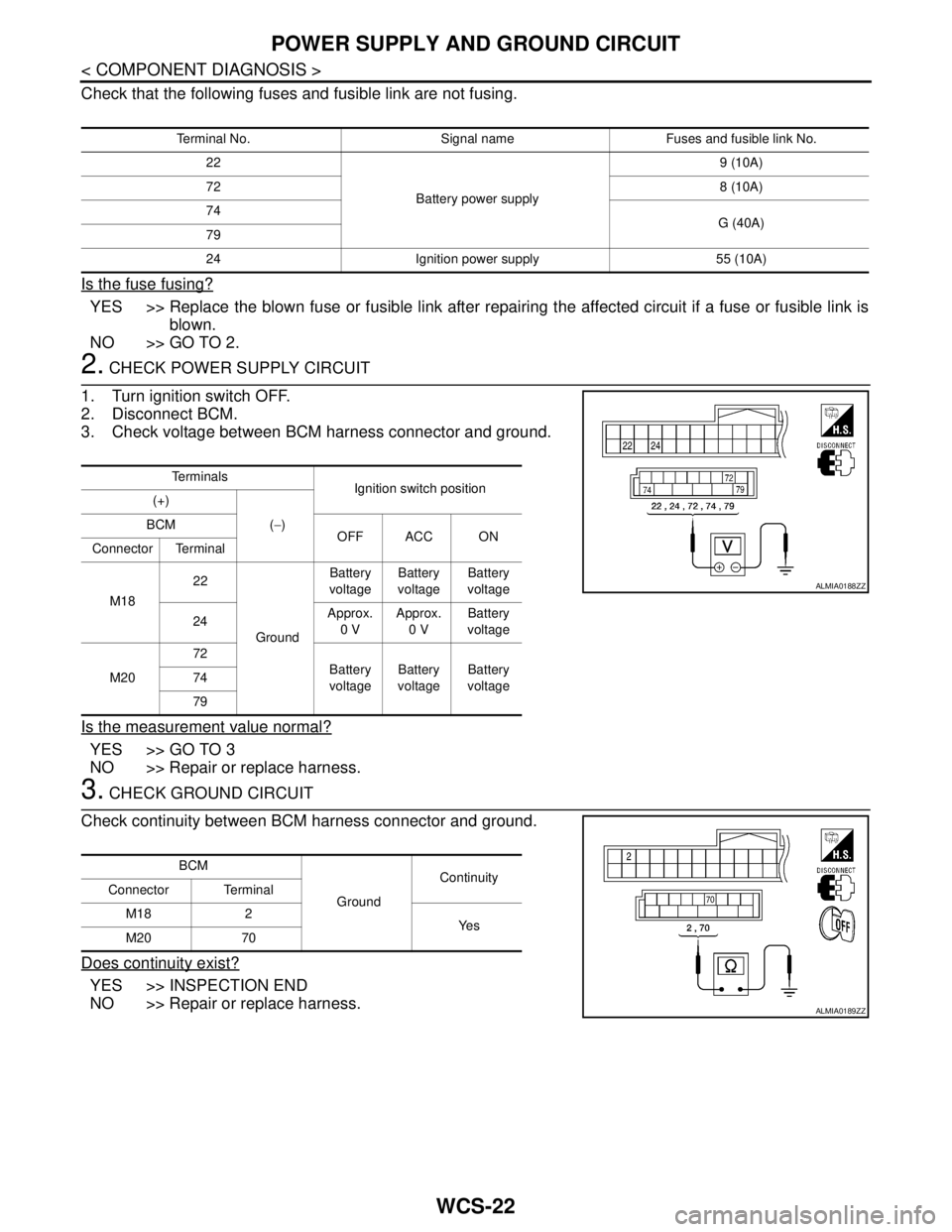
Check that the following fuses and fusible link are not fusing.
Is the fuse fusing?
YES >> Replace the blown fuse or fusible link after repairing the affected circuit if a fuse or fusible link is
blown.
NO >> GO TO 2.
2. CHECK POWER SUPPLY CIRCUIT
1. Turn ignition switch OFF.
2. Disconnect BCM.
3. Check voltage between BCM harness connector and ground.
Is the measurement value normal?
YES >> GO TO 3
NO >> Repair or replace harness.
3. CHECK GROUND CIRCUIT
Check continuity between BCM harness connector and ground.
Does continuity exist?
YES >> INSPECTION END
NO >> Repair or replace harness.
Terminal No. Signal name Fuses and fusible link No.
22
Battery power supply9 (10A)
728 (10A)
74
G (40A)
79
24 Ignition power supply 55 (10A)
Te r m i n a l s
Ignition switch position
(+)
(−) BCM
OFF ACC ON
Connector Terminal
M1822
GroundBattery
voltageBattery
voltageBattery
voltage
24Approx.
0 VApprox.
0 VBattery
voltage
M2072
Battery
voltageBattery
voltageBattery
voltage 74
79
ALMIA0188ZZ
BCM
GroundContinuity
Connector Terminal
M18 2
Ye s
M20 70
ALMIA0189ZZ
Page 5742 of 5883

WCS
KEY SWITCH SIGNAL CIRCUIT (WITH INTELLIGENT KEY)
WCS-27
< COMPONENT DIAGNOSIS >
C
D
E
F
G
H
I
J
K
L
MB A
O
P
Is the inspection result normal?
YES >> GO TO 4
NO >> Repair harness or connector.
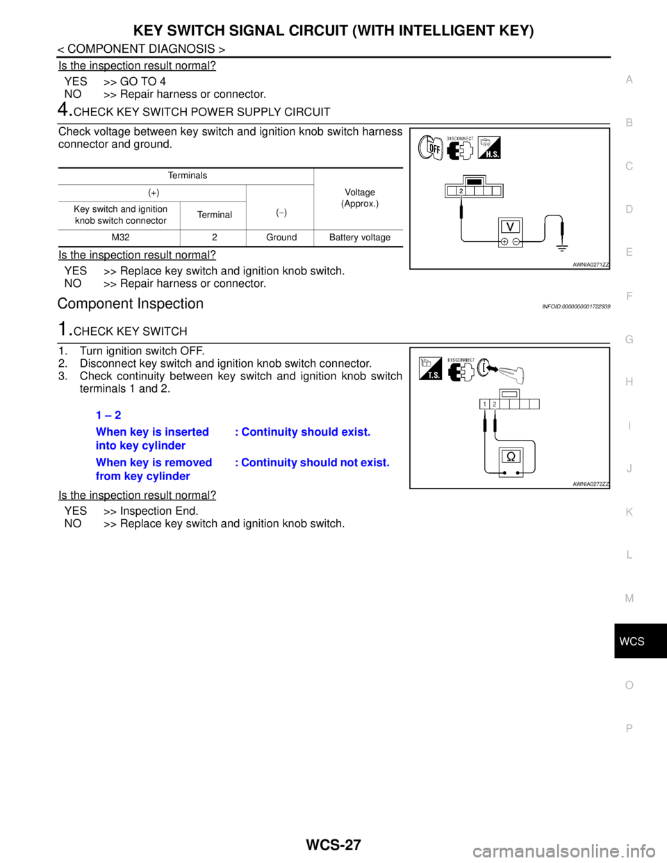
4.CHECK KEY SWITCH POWER SUPPLY CIRCUIT
Check voltage between key switch and ignition knob switch harness
connector and ground.
Is the inspection result normal?
YES >> Replace key switch and ignition knob switch.
NO >> Repair harness or connector.
Component InspectionINFOID:0000000001722939
1.CHECK KEY SWITCH
1. Turn ignition switch OFF.
2. Disconnect key switch and ignition knob switch connector.
3. Check continuity between key switch and ignition knob switch
terminals 1 and 2.
Is the inspection result normal?
YES >> Inspection End.
NO >> Replace key switch and ignition knob switch.
Te r m i n a l s
Vo l ta g e
(Approx.) (+)
(−) Key switch and ignition
knob switch connector Te r m i n a l
M32 2 Ground Battery voltage
AWNIA0271ZZ
1 – 2
When key is inserted
into key cylinder: Continuity should exist.
When key is removed
from key cylinder: Continuity should not exist.
AWNIA0272ZZ
Page 5744 of 5883

WCS
KEY SWITCH SIGNAL CIRCUIT (WITHOUT INTELLIGENT KEY)
WCS-29
< COMPONENT DIAGNOSIS >
C
D
E
F
G
H
I
J
K
L
MB A
O
P
Is the inspection result normal?
YES >> GO TO 4
NO >> Repair harness or connector.
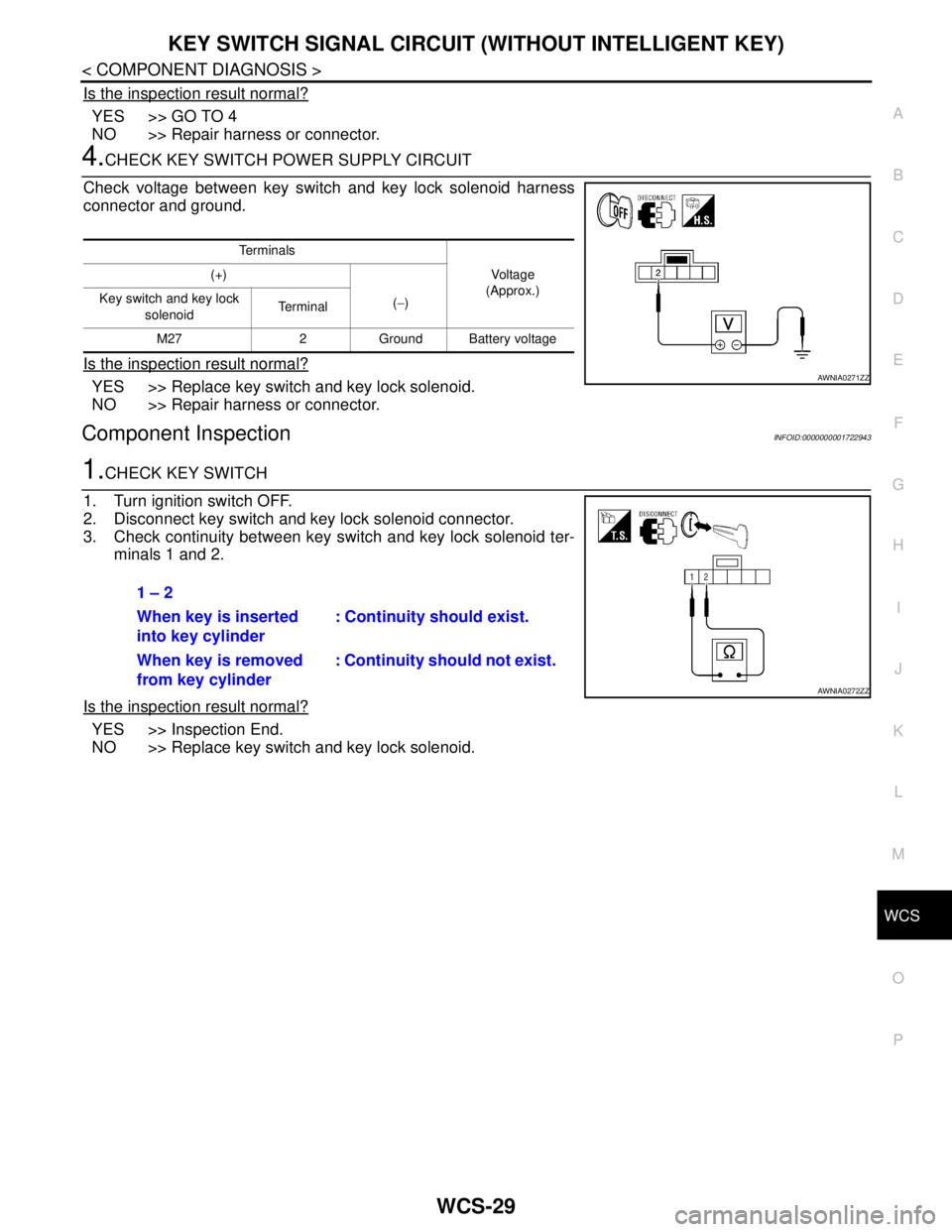
4.CHECK KEY SWITCH POWER SUPPLY CIRCUIT
Check voltage between key switch and key lock solenoid harness
connector and ground.
Is the inspection result normal?
YES >> Replace key switch and key lock solenoid.
NO >> Repair harness or connector.
Component InspectionINFOID:0000000001722943
1.CHECK KEY SWITCH
1. Turn ignition switch OFF.
2. Disconnect key switch and key lock solenoid connector.
3. Check continuity between key switch and key lock solenoid ter-
minals 1 and 2.
Is the inspection result normal?
YES >> Inspection End.
NO >> Replace key switch and key lock solenoid.
Te r m i n a l s
Vo l ta g e
(Approx.) (+)
(−) Key switch and key lock
solenoid Te r m i n a l
M27 2 Ground Battery voltage
AWNIA0271ZZ
1 – 2
When key is inserted
into key cylinder: Continuity should exist.
When key is removed
from key cylinder: Continuity should not exist.
AWNIA0272ZZ
Page 5821 of 5883
FRONT WIPER MOTOR LO CIRCUIT
WW-19
< COMPONENT DIAGNOSIS >
C
D
E
F
G
H
I
J
K
MA
B
WW
N
O
P
1. Turn the ignition switch ON.
2. Select "FRONT WIPER" of IPDM E/R active test item.
3. While operating the test item, check voltage between IPDM E/R
harness connector and ground.
Is the measurement value normal?
YES >> GO TO 4
NO >> Replace IPDM E/R. Refer to xxx.
4. CHECK FRONT WIPER MOTOR (LO) OPEN CIRCUIT
1. Turn the ignition switch OFF.
2. Disconnect IPDM E/R and front wiper motor.
3. Check continuity between IPDM E/R harness connector and
front wiper motor harness connector.
Does continuity exist?
YES >> Replace front wiper motor. Refer to WW-73, "Removal
and Installation".
NO >> Repair or replace harness.
Te r m i n a l s
Te s t i t e m
Voltage
(Approx.) (+) (-)
IPDM E/R
GroundFRONT WIPER
Connector Terminal
E45 33LOBattery
voltage
OFF 0V
ALLIA0343ZZ
IPDM E/R Front wiper motor
Continuity
Connector Terminal Connector Terminal
E45 (A) 10 E1 (B) 3 Yes
ALLIA0344ZZ
Page 5823 of 5883
FRONT WIPER MOTOR HI CIRCUIT
WW-21
< COMPONENT DIAGNOSIS >
C
D
E
F
G
H
I
J
K
MA
B
WW
N
O
P
1. Turn the ignition switch ON.
2. Select "FRONT WIPER" of IPDM E/R active test item.
3. While operating the test item, check voltage between IPDM E/R
harness connector and ground.
Is the measurement value normal?
YES >> GO TO 4
NO >> Replace IPDM E/R. Refer to xxx.
4. CHECK FRONT WIPER MOTOR (HI) OPEN CIRCUIT
1. Turn the ignition switch OFF.
2. Disconnect IPDM E/R and front wiper motor.
3. Check continuity between IPDM E/R harness connector and
front wiper motor harness connector.
Does continuity exist?
YES >> Replace front wiper motor. Refer to WW-73, "Removal
and Installation".
NO >> Repair or replace harness.
Te r m i n a l s
Te s t i t e m
Voltage
(Approx.) (+) (-)
IPDM E/R
GroundFRONT WIP-
ER
Connector Terminal
E45 32HIBattery
voltage
OFF 0 V
ALLIA0346ZZ
IPDM E/R Front wiper motor
Continuity
Connector Terminal Connector Terminal
E45 (A) 32 E1 (B) 5 Yes
ALLIA0347ZZ