Page 476 of 5883
CSC (CONCENTRIC SLAVE CYLINDER)
CL-11
< SERVICE INFORMATION >
C
E
F
G
H
I
J
K
L
MA
B
CL
N
O
P
CSC (CONCENTRIC SLAVE CYLINDER)
Removal and InstallationINFOID:0000000001375297
CAUTION:
If transaxle assembly is removed from the vehicle, always replace CSC (Concentric slave cylinder).
Return CSC insert to original position to remove transaxle assembly. Dust on clutch disc sliding
parts may damage CSC seal and may cause clutch fluid leakage.
Keep painted surface of the body and other parts free of clutch fluid. If it spills, wipe up immediately
and wash the affected area with water.
REMOVAL
1. Remove transaxle assembly. Refer to TM-633, "Removal and Installation" (5MT) or TM-681, "Removal
and Installation" (6MT).
2. Remove CSC bolts and the CSC from clutch housing.
INSTALLATION
Installation is in the reverse order of removal.
CAUTION:
After installation, bleed the air from the clutch hydraulic system. Refer to CL-8, "
Air Bleeding Proce-
dure".
PCIB1498E
Page 502 of 5883
WATER PUMP
CO-21
< ON-VEHICLE REPAIR >[HR16DE]
C
D
E
F
G
H
I
J
K
L
MA
CO
N
P O
Tighten bolts in numerical order as shown.
Water pump pulley.
CAUTION:
Never install mounting bolts (A) to oblong holes (B).
Water pump pulley (1)
InspectionINFOID:0000000001381570
INSPECTION AFTER REMOVAL
Visually check if there is no significant dirt or rusting on water
pump body and vane (A).
Make sure that there is no looseness in vane shaft, and that it turns
smoothly when rotated by hand.
Replace water pump, if necessary.
INSPECTION AFTER INSTALLATION
Check that the reservoir tank cap is tightened.
Check for leaks of engine coolant using suitable tools. Refer to CO-11, "
Inspection".
Start and warm up the engine. Visually make sure that there is no leaks of engine coolant.
KBIA3393J
PBIC3809E
PBIC3808E
Page 525 of 5883
![NISSAN TIIDA 2007 Service Repair Manual CO-44
< ON-VEHICLE REPAIR >[MR18DE]
WATER PUMP
WATER PUMP
ComponentINFOID:0000000001337848
Removal and InstallationINFOID:0000000001337849
REMOVAL
1. Drain engine coolant. Refer to CO-35, "Changing En NISSAN TIIDA 2007 Service Repair Manual CO-44
< ON-VEHICLE REPAIR >[MR18DE]
WATER PUMP
WATER PUMP
ComponentINFOID:0000000001337848
Removal and InstallationINFOID:0000000001337849
REMOVAL
1. Drain engine coolant. Refer to CO-35, "Changing En](/manual-img/5/57395/w960_57395-524.png)
CO-44
< ON-VEHICLE REPAIR >[MR18DE]
WATER PUMP
WATER PUMP
ComponentINFOID:0000000001337848
Removal and InstallationINFOID:0000000001337849
REMOVAL
1. Drain engine coolant. Refer to CO-35, "Changing Engine Coolant".
CAUTION:
Perform this step when the engine is cold.
2. Remove drive belt auto-tensioner. Refer to EM-153, "
Removal and Installation of Drive Belt Auto Ten-
sioner".
3. Remove water pump.
CAUTION:
Handle water pump vane so that it does not contact any other parts.
Water pump cannot be disassembled and should be replaced as a unit.
INSPECTION AFTER REMOVAL
Visually check that there is no significant dirt or rusting on water
pump body and vane (A).
Make sure that there is no looseness in vane shaft, and that it turns
smoothly when rotated by hand.
Replace water pump, if necessary.
INSTALLATION
Installation is in the reverse order of removal.
INSPECTION AFTER INSTALLATION
Check for leaks of engine coolant. Refer to CO-35, "Inspection".
Start and warm up the engine. Visually check if there is no leaks of engine coolant.
1. Gasket 2. Water pump
PBIC3921E
PBIC3313J
Page 548 of 5883
WATER PUMP
CO-67
< ON-VEHICLE REPAIR >[K9K]
C
D
E
F
G
H
I
J
K
L
MA
CO
N
P O
Visually make sure there is no significant dirt or rusting on the
water pump body and vane.
Make sure there is no looseness in the vane shaft, and that it turns
smoothly when rotated by hand.
If there are any defects, replace the water pump assembly.
INSPECTION AFTER INSTALLATION
Check for engine coolant leaks using suitable tools. Refer to CO-58, "Inspection".
MBIB0546E
Page 552 of 5883

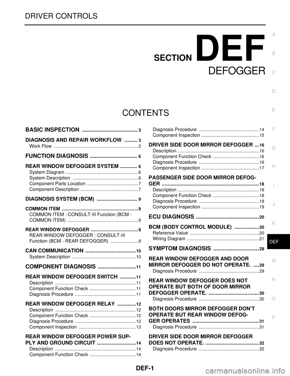
DEF-1
DRIVER CONTROLS
C
D
E
F
G
H
I
J
K
M
SECTION DEF
A
B
DEF
N
O
P
CONTENTS
DEFOGGER
BASIC INSPECTION ....................................3
DIAGNOSIS AND REPAIR WORKFLOW ..........3
Work Flow .................................................................3
FUNCTION DIAGNOSIS ...............................6
REAR WINDOW DEFOGGER SYSTEM .............6
System Diagram ........................................................6
System Description ...................................................6
Component Parts Location ........................................7
Component Description .............................................7
DIAGNOSIS SYSTEM (BCM) .............................9
COMMON ITEM ...........................................................9
COMMON ITEM : CONSULT-III Function (BCM -
COMMON ITEM) .......................................................
9
REAR WINDOW DEFOGGER .....................................9
REAR WINDOW DEFOGGER : CONSULT-III
Function (BCM - REAR DEFOGGER) ......................
9
CAN COMMUNICATION ....................................10
System Description .................................................10
COMPONENT DIAGNOSIS .........................11
REAR WINDOW DEFOGGER SWITCH ............11
Description ..............................................................11
Component Function Check ....................................11
Diagnosis Procedure ...............................................11
REAR WINDOW DEFOGGER RELAY ..............12
Description ..............................................................12
Component Function Check ....................................12
Diagnosis Procedure ...............................................12
Component Inspection ............................................13
REAR WINDOW DEFOGGER POWER SUP-
PLY AND GROUND CIRCUIT ............................
14
Description ..............................................................14
Component Function Check ....................................14
Diagnosis Procedure ...............................................14
Component Inspection .............................................15
DRIVER SIDE DOOR MIRROR DEFOGGER ...16
Description ...............................................................16
Component Function Check ....................................16
Diagnosis Procedure ...............................................16
Component Inspection .............................................17
PASSENGER SIDE DOOR MIRROR DEFOG-
GER ...................................................................
18
Description ...............................................................18
Component Function Check ....................................18
Diagnosis Procedure ...............................................18
Component Inspection .............................................19
ECU DIAGNOSIS .........................................20
BCM (BODY CONTROL MODULE) .................20
Reference Value ......................................................20
Wiring Diagram ........................................................21
SYMPTOM DIAGNOSIS ..............................29
REAR WINDOW DEFOGGER AND DOOR
MIRROR DEFOGGER DO NOT OPERATE. ....
29
Diagnosis Procedure ...............................................29
REAR WINDOW DEFOGGER DOES NOT
OPERATE BUT BOTH OF DOOR MIRROR
DEFOGGER OPERATE. ...................................
30
Diagnosis Procedure ...............................................30
BOTH DOORS MIRROR DEFOGGER DON’T
OPERATE BUT REAR WINDOW DEFOG-
GER OPERATES ..............................................
31
Diagnosis Procedure ...............................................31
DRIVER SIDE DOOR MIRROR DEFOGGER
DOES NOT OPERATE. .....................................
32
Diagnosis Procedure ...............................................32
Page 571 of 5883
DEF-20
< ECU DIAGNOSIS >
BCM (BODY CONTROL MODULE)
ECU DIAGNOSIS
BCM (BODY CONTROL MODULE)
Reference ValueINFOID:0000000001697567
VALUES ON THE DIAGNOSIS TOOL
TERMINAL LAYOUT
Refer to XX-XX, "*****".
PHYSICAL VALUES
Refer to XX-XX, "*****".
Monitor Item Condition Value/Status
REAR DEF SWNOTE:
The item is indicated, but not monitored. OFF
Page 572 of 5883
BCM (BODY CONTROL MODULE)
DEF-21
< ECU DIAGNOSIS >
C
D
E
F
G
H
I
J
K
MA
B
DEF
N
O
P
Wiring DiagramINFOID:0000000001697568
ALLWA0121GB
Page 573 of 5883
DEF-22
< ECU DIAGNOSIS >
BCM (BODY CONTROL MODULE)
ALLIA0659GB