Page 5812 of 5883
WW-10
< FUNCTION DIAGNOSIS >
REAR WIPER AND WASHER SYSTEM
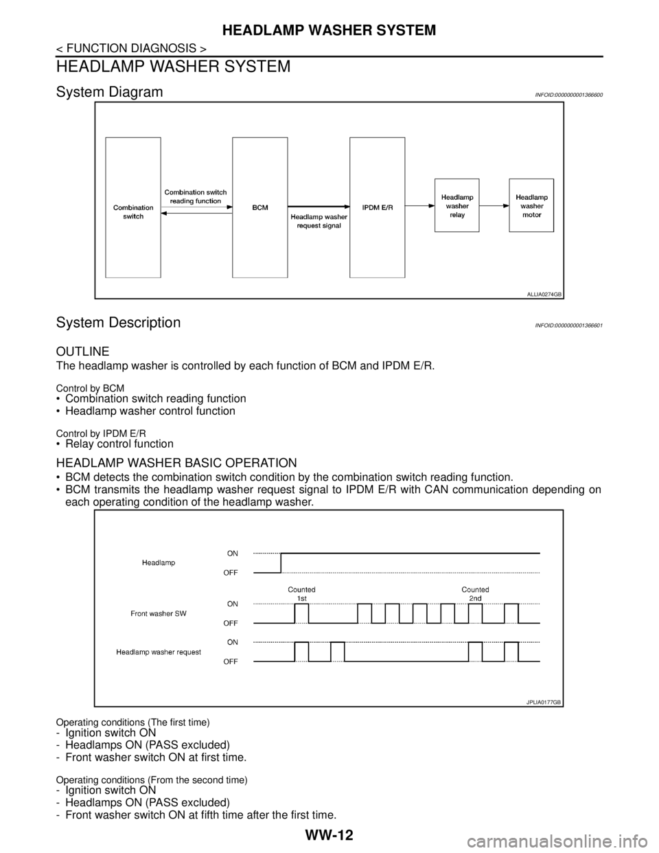
BCM reads an auto stop signal from the rear wiper motor to detect a rear wiper motor position.
When the rear wiper motor is at other than the stopping position, BCM continues to supply power to the rear
wiper motor until it returns to the stopping position.
NOTE:
BCM stops supplying power to the rear wiper motor when the ignition switch is turned OFF.
REAR WIPER OPERATION LINKED WITH WASHER
BCM supplies power to the rear wiper motor according to the washer linked operating condition of rear
wiper. When the rear washer switch is turned OFF, BCM controls rear wiper to operate approximately three
times.
Washer linked operating condition of rear wiper- Ignition switch ON
- Rear washer switch ON (0.4 second or more)
Washer pump becomes grounded through the combination switch when the rear washer switch is turned
ON.
REAR WIPER DROP WIPE OPERATION
BCM controls the rear wiper to operate once according to the rear wiper drop wipe operating condition.
Rear wiper drop wipe operating condition
- Ignition switch ON
- Rear wiper switch OFF
- Rear washer switch OFF
BCM controls the rear wiper so that it operates once time approximately three seconds later after the washer
interlocking operation of the rear wiper.
JPLIA0166GB
Page 5814 of 5883
WW-12
< FUNCTION DIAGNOSIS >
HEADLAMP WASHER SYSTEM
HEADLAMP WASHER SYSTEM
System DiagramINFOID:0000000001366600
System DescriptionINFOID:0000000001366601
OUTLINE
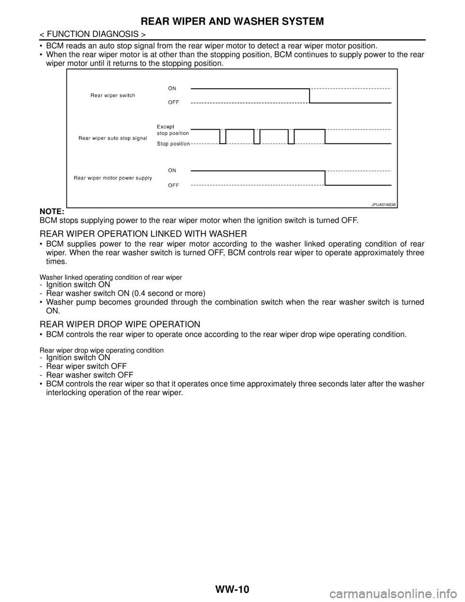
The headlamp washer is controlled by each function of BCM and IPDM E/R.
Control by BCM Combination switch reading function
Headlamp washer control function
Control by IPDM E/R Relay control function
HEADLAMP WASHER BASIC OPERATION
BCM detects the combination switch condition by the combination switch reading function.
BCM transmits the headlamp washer request signal to IPDM E/R with CAN communication depending on
each operating condition of the headlamp washer.
Operating conditions (The first time)
- Ignition switch ON
- Headlamps ON (PASS excluded)
- Front washer switch ON at first time.
Operating conditions (From the second time)- Ignition switch ON
- Headlamps ON (PASS excluded)
- Front washer switch ON at fifth time after the first time.
ALLIA0274GB
JPLIA0177GB
Page 5816 of 5883

WW-14
< FUNCTION DIAGNOSIS >
DIAGNOSIS SYSTEM (BCM)
DIAGNOSIS SYSTEM (BCM)
COMMON ITEM
COMMON ITEM : CONSULT-III Function (BCM - COMMON ITEM)INFOID:0000000001366604
APPLICATION ITEM
CONSULT-III performs the following functions via CAN communication with BCM.
SYSTEM APPLICATION
BCM can perform the following functions for each system.
NOTE:
It can perform the diagnosis modes except the following for all sub system selection items.
WIPER
WIPER : CONSULT-III Function (BCM - WIPER)INFOID:0000000001366605
WORK SUPPORT
*:Factory setting
DATA MONITOR
Diagnosis mode Function Description
WORK SUPPORT Changes the setting for each system function.
SELF-DIAG RESULTS Displays the diagnosis results judged by BCM. Refer to BCS-54, "
DTCIndex".
CAN DIAG SUPPORT MNTR Monitors the reception status of CAN communication viewed from BCM.
DATA MONITOR The BCM input/output signals are displayed.
ACTIVE TEST The signals used to activate each device are forcibly supplied from BCM.
ECU IDENTIFICATION The BCM part number is displayed.
CONFIGURATION Enables to read and save the vehicle specification.
Enables to write the vehicle specification when replacing BCM.
System Sub system selection itemDiagnosis mode
WORK SUPPORT DATA MONITOR ACTIVE TEST
—BCM×
Exterior lamp HEAD LAMP×××
Wiper and washer WIPER×××
Combination switch COMB SW×
Back door switch DOOR LOCK××
Service itemSetting
itemDescription
WIPER SPEED
SETTINGON*With vehicle speed
(Front wiper intermittent time linked with the vehicle speed and wiper intermittent dial position)
OFFWithout vehicle speed
(Front wiper intermittent time linked with the wiper intermittent dial position)
Monitor Item
[Unit]Description
IGN ON SW Ignition switch ON status judged from ignition power supply.
IGN SW CAN Ignition switch ON status received from IPDM E/R with CAN communication.
Page 5818 of 5883

WW-16
< FUNCTION DIAGNOSIS >
DIAGNOSIS SYSTEM (IPDM E/R)
DIAGNOSIS SYSTEM (IPDM E/R)
Diagnosis DescriptionINFOID:0000000001366606
AUTO ACTIVE TEST
Refer to PCS IPDM E/R AUTO ACTIVE TEST.
CONSULT - III Function (IPDM E/R)INFOID:0000000001366607
APPLICATION ITEM
CONSULT-III performs the following functions via CAN communication with IPDM E/R.
SELF DIAGNOSTIC
Refer to PCS-28, "DTCIndex".
DATA MONITOR
Monitor item
ACTIVE TEST
Te s t i t e m
Diagnosis mode Description
ECU Identification Allows confirmation of IPDM E/R part number.
Self Diagnostic Result Displays the diagnosis results judged by IPDM E/R.
Data Monitor Displays the real-time input/output data from IPDM E/R input/output data.
Active Test IPDM E/R can provide a drive signal to electronic components to check their operations.
CAN Diag Support Monitor The results of transmit/receive diagnosis of CAN communication can be read.
Monitor Item
[Unit]MAIN
SIGNALSDescription
HL WASHER REQ
[Off/On]Displays the status of the headlamp washer request signal received from BCM via CAN
communication.
FR WIP REQ
[Stop/1LOW/Low/Hi]×Displays the status of the front wiper request signal received from BCM via CAN com-
munication.
WIP AUTO STOP
[STOP P/ACT P]×Displays the status of the front wiper auto stop signal judged by IPDM E/R.
WIP PROT
[Off/BLOCK]×Displays the status of the front wiper fail-safe operation judged by IPDM E/R.
IGN RLY
[Off/On]×Displays the status of the ignition relay judged by IPDM E/R.
IGN ON SW
[Off/On]Displays the status of the ignition switch judged by IPDM E/R.
Test item Operation Description
FRONT WIPEROff OFF
Lo Operates the front wiper relay.
Hi Operates the front wiper relay and front wiper high relay.
HEAD LAMP WASHER On Operates the headlamp washer relay for 1 second.
EXTERNAL LAMPSOff OFF
TAIL Operates the tail lamp relay.
Lo Operates the headlamp low relay.
HiOperates the headlamp low relay and ON/OFF the headlamp high relay at 1 sec-
ond intervals.
Fog Operates the front fog lamp relay.
Page 5854 of 5883

WW-52
< ECU DIAGNOSIS >
IPDM E/R (INTELLIGENT POWER DISTRIBUTION MODULE ENGINE ROOM)
IPDM E/R (INTELLIGENT POWER DISTRIBUTION MODULE ENGINE
ROOM)
Reference ValueINFOID:0000000001366636
VALUES ON THE DIAGNOSIS TOOL
TERMINAL LAYOUT
Refer to xxx.
PHYSICAL VALUES
Refer to xxx.
Fail SafeINFOID:0000000001366638
CAN communication control
When CAN communication with ECM and BCM is impossible, IPDM E/R performs fail-safe control. After CAN
communication recovers normally, it also returns to normal control.
If no CAN communication is available with BCM
Front wiper control
IPDM E/R detects the front wiper stop position with the front wiper auto stop signal.
When the front wiper auto stop signal is in the conditions listed below, IPDM E/R repeats a front wiper 10 sec-
onds operation and 20 seconds stop five times.
Monitor Item Condition Value/Status
HL WASHER REQIgnition switch ON, and low
beam headlamp is ONFront washer switch OFF Off
Front washer switch ON
(When headlamp washer is operat-
ing)On
FR WIP REQ Ignition switch ONFront wiper switch OFF STOP
Front wiper switch INT 1LOW
Front wiper switch LO Low
Front wiper switch HI Hi
WIP AUTO STOP Ignition switch ONFront wiper stop position STOP P
Any position other than front wiper
stop positionACT P
WIP PROT Ignition switch ONFront wiper operates normally Off
Front wiper stops at fail-safe oper-
ationBLOCK
IGN RLYIgnition switch OFF or ACC Off
Ignition switch ON On
IGN ON SWIgnition switch OFF or ACC Off
Ignition switch ON On
Control part Fail-safe in operation
Front wiper The status just before activation of fail-safe control is maintained until the ignition
switch is turned OFF while the front wiper is operating at LO or HI speed.
The front wiper is operated at LO speed until the ignition switch is turned OFF if the
fail-safe control is activated while the front wiper is set in the INT mode and the front
wiper motor is operating.
Headlamp washer Headlamp washer relay OFF
Page 5859 of 5883
NORMAL OPERATING CONDITION
WW-57
< SYMPTOM DIAGNOSIS >
C
D
E
F
G
H
I
J
K
MA
B
WW
N
O
P
NORMAL OPERATING CONDITION
DescriptionINFOID:0000000001366641
FRONT WIPER MOTOR PROTECTION FUNCTION
IPDM E/R may stop the front wiper to protect the front wiper motor if any obstruction (operation resistance)
such as a large amount of snow is detected during the front wiper operation.
At that time turn OFF the front wiper and remove the foreign object. Then wait for approximately 20 seconds
or more and reactivate the front wiper. The wiper will operate normally.
REAR WIPER MOTOR PROTECTION FUNCTION
BCM may stop rear wiper to protect the rear wiper motor when the rear wiper is stopped for 5 seconds or
more due to a snowfall.
Rear wiper operates normally one minute after the obstacles are removed with rear wiper OFF.