Page 5770 of 5883

WCS
COMBINATION METER
WCS-55
< ECU DIAGNOSIS >
C
D
E
F
G
H
I
J
K
L
MB A
O
P
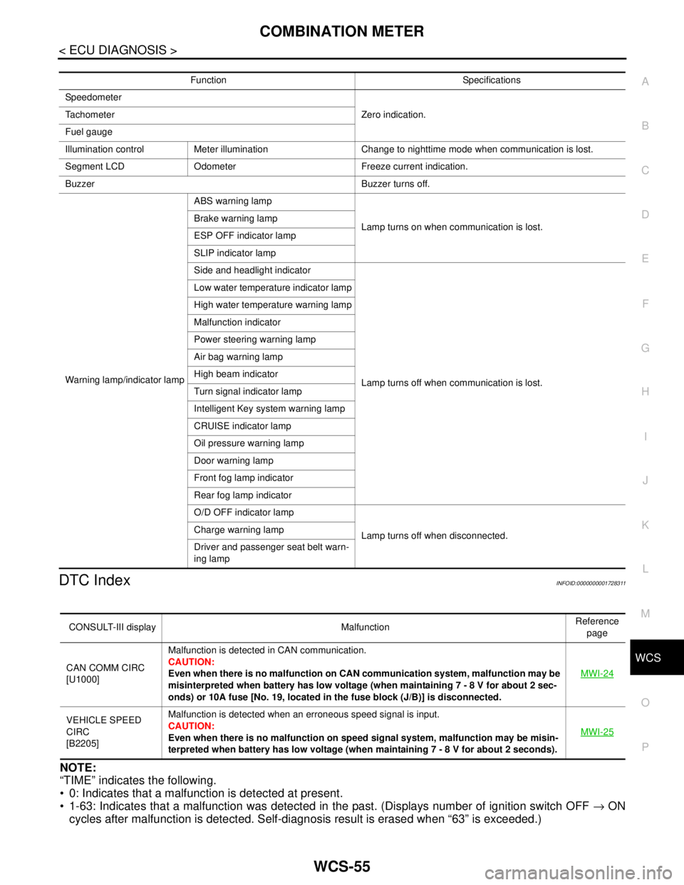
DTC IndexINFOID:0000000001728311
NOTE:
“TIME” indicates the following.
0: Indicates that a malfunction is detected at present.
1-63: Indicates that a malfunction was detected in the past. (Displays number of ignition switch OFF → ON
cycles after malfunction is detected. Self-diagnosis result is erased when “63” is exceeded.)
Function Specifications
Speedometer
Zero indication. Tachometer
Fuel gauge
Illumination control Meter illumination Change to nighttime mode when communication is lost.
Segment LCD Odometer Freeze current indication.
Buzzer Buzzer turns off.
Warning lamp/indicator lampABS warning lamp
Lamp turns on when communication is lost. Brake warning lamp
ESP OFF indicator lamp
SLIP indicator lamp
Side and headlight indicator
Lamp turns off when communication is lost. Low water temperature indicator lamp
High water temperature warning lamp
Malfunction indicator
Power steering warning lamp
Air bag warning lamp
High beam indicator
Turn signal indicator lamp
Intelligent Key system warning lamp
CRUISE indicator lamp
Oil pressure warning lamp
Door warning lamp
Front fog lamp indicator
Rear fog lamp indicator
O/D OFF indicator lamp
Lamp turns off when disconnected. Charge warning lamp
Driver and passenger seat belt warn-
ing lamp
CONSULT-III display MalfunctionReference
page
CAN COMM CIRC
[U1000]Malfunction is detected in CAN communication.
CAUTION:
Even when there is no malfunction on CAN communication system, malfunction may be
misinterpreted when battery has low voltage (when maintaining 7 - 8 V for about 2 sec-
onds) or 10A fuse [No. 19, located in the fuse block (J/B)] is disconnected.MWI-24
VEHICLE SPEED
CIRC
[B2205]Malfunction is detected when an erroneous speed signal is input.
CAUTION:
Even when there is no malfunction on speed signal system, malfunction may be misin-
terpreted when battery has low voltage (when maintaining 7 - 8 V for about 2 seconds). MWI-25
Page 5772 of 5883

WCS
BCM (BODY CONTROL MODULE)
WCS-57
< ECU DIAGNOSIS >
C
D
E
F
G
H
I
J
K
L
MB A
O
P
ENGINE RUNEngine stopped OFF
Engine running ON
ENGINE STATUS
NOTE:
Diesel engine models
onlyEngine stopped STOP
While the engine stalls STALL
Engine running RUN
At engine cranking CRA
FA N O N S IGFan switch OFF OFF
Fan switch ON ON
FR FOG SWFront fog lamp switch OFF OFF
Front fog lamp switch ON ON
FR WASHER SWFront washer switch OFF OFF
Front washer switch ON ON
FR WIPER LOWFront wiper switch OFF OFF
Front wiper switch LO ON
FR WIPER HIFront wiper switch OFF OFF
Front wiper switch HI ON
FR WIPER INTFront wiper switch OFF OFF
Front wiper switch INT ON
FR WIPER STOPAny position other than front wiper stop position OFF
Front wiper stop position ON
HAZARD SWWhen hazard switch is not pressed OFF
When hazard switch is pressed ON
LIGHT SW 1STLighting switch OFF OFF
Lighting switch 1st ON
H/L SW POSHeadlamp switch OFF OFF
Headlamp switch 1st ON
HI BEAM SWHigh beam switch OFF OFF
High beam switch HI ON
HOOD SWClose the hood
NOTE:
Vehicles without theft warning system are OFF-fixedOFF
Open the hood ON
H/L WASH SWNOTE:
The item is indicated, but not monitoredOFF
IGN ON SWIgnition switch OFF or ACC OFF
Ignition switch ON ON
IGN SW CANIgnition switch OFF or ACC OFF
Ignition switch ON ON
INT VOLUME Wiper intermittent dial is in a dial position 1 - 7 1 - 7
I-KEY LOCK
1LOCK button of Intelligent Key is not pressed OFF
LOCK button of Intelligent Key is pressed ON
I-KEY UNLOCK
1UNLOCK button of Intelligent Key is not pressed OFF
UNLOCK button of Intelligent Key is pressed ON
KEY SW
2Mechanical key is removed from key cylinder OFF
Mechanical key is inserted to key cylinder ON Monitor Item Condition Value/Status
Page 5853 of 5883

BCM (BODY CONTROL MODULE)
WW-51
< ECU DIAGNOSIS >
C
D
E
F
G
H
I
J
K
MA
B
WW
N
O
P
ECU DIAGNOSIS
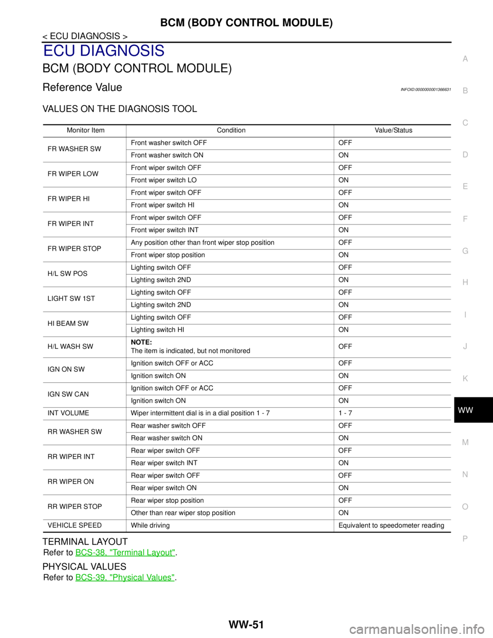
BCM (BODY CONTROL MODULE)
Reference ValueINFOID:0000000001366631
VALUES ON THE DIAGNOSIS TOOL
TERMINAL LAYOUT
Refer to BCS-38, "Terminal Layout".
PHYSICAL VALUES
Refer to BCS-39, "Physical Values".
Monitor Item Condition Value/Status
FR WASHER SWFront washer switch OFF OFF
Front washer switch ON ON
FR WIPER LOWFront wiper switch OFF OFF
Front wiper switch LO ON
FR WIPER HIFront wiper switch OFF OFF
Front wiper switch HI ON
FR WIPER INTFront wiper switch OFF OFF
Front wiper switch INT ON
FR WIPER STOPAny position other than front wiper stop position OFF
Front wiper stop position ON
H/L SW POSLighting switch OFF OFF
Lighting switch 2ND ON
LIGHT SW 1STLighting switch OFF OFF
Lighting switch 2ND ON
HI BEAM SWLighting switch OFF OFF
Lighting switch HI ON
H/L WASH SWNOTE:
The item is indicated, but not monitoredOFF
IGN ON SWIgnition switch OFF or ACC OFF
Ignition switch ON ON
IGN SW CANIgnition switch OFF or ACC OFF
Ignition switch ON ON
INT VOLUME Wiper intermittent dial is in a dial position 1 - 7 1 - 7
RR WASHER SWRear washer switch OFF OFF
Rear washer switch ON ON
RR WIPER INTRear wiper switch OFF OFF
Rear wiper switch INT ON
RR WIPER ON Rear wiper switch OFF OFF
Rear wiper switch ON ON
RR WIPER STOPRear wiper stop position OFF
Other than rear wiper stop position ON
VEHICLE SPEED While driving Equivalent to speedometer reading
Page 5854 of 5883

WW-52
< ECU DIAGNOSIS >
IPDM E/R (INTELLIGENT POWER DISTRIBUTION MODULE ENGINE ROOM)
IPDM E/R (INTELLIGENT POWER DISTRIBUTION MODULE ENGINE
ROOM)
Reference ValueINFOID:0000000001366636
VALUES ON THE DIAGNOSIS TOOL
TERMINAL LAYOUT
Refer to xxx.
PHYSICAL VALUES
Refer to xxx.
Fail SafeINFOID:0000000001366638
CAN communication control
When CAN communication with ECM and BCM is impossible, IPDM E/R performs fail-safe control. After CAN
communication recovers normally, it also returns to normal control.
If no CAN communication is available with BCM
Front wiper control
IPDM E/R detects the front wiper stop position with the front wiper auto stop signal.
When the front wiper auto stop signal is in the conditions listed below, IPDM E/R repeats a front wiper 10 sec-
onds operation and 20 seconds stop five times.
Monitor Item Condition Value/Status
HL WASHER REQIgnition switch ON, and low
beam headlamp is ONFront washer switch OFF Off
Front washer switch ON
(When headlamp washer is operat-
ing)On
FR WIP REQ Ignition switch ONFront wiper switch OFF STOP
Front wiper switch INT 1LOW
Front wiper switch LO Low
Front wiper switch HI Hi
WIP AUTO STOP Ignition switch ONFront wiper stop position STOP P
Any position other than front wiper
stop positionACT P
WIP PROT Ignition switch ONFront wiper operates normally Off
Front wiper stops at fail-safe oper-
ationBLOCK
IGN RLYIgnition switch OFF or ACC Off
Ignition switch ON On
IGN ON SWIgnition switch OFF or ACC Off
Ignition switch ON On
Control part Fail-safe in operation
Front wiper The status just before activation of fail-safe control is maintained until the ignition
switch is turned OFF while the front wiper is operating at LO or HI speed.
The front wiper is operated at LO speed until the ignition switch is turned OFF if the
fail-safe control is activated while the front wiper is set in the INT mode and the front
wiper motor is operating.
Headlamp washer Headlamp washer relay OFF