Page 3326 of 5883
HA-44
< ON-VEHICLE REPAIR >
HIGH-PRESSURE PIPE
7. Remove bolt (A), and then disconnect the low-pressure pipe (1)
and high-pressure pipe (2) from the expansion valve.
CAUTION:
Cap or wrap the joint of the pipe with suitable material such
as vinyl tape to avoid the entry of air.
8. Disconnect the high-pressure pipe from the condenser.
CAUTION:
Cap or wrap the joint of the pipe with suitable material such as vinyl tape to avoid the entry of air.
9. Remove the upper torque rod. Refer to FSU-9, "
Component".
10. Disconnect the high-pressure pipe from the clips.
11. Remove the high-pressure pipe.
INSTALLATION
Installation is in the reverse order of removal.
CAUTION:
Replace O-rings for A/C piping with new ones, and apply compressor oil when installing.
When charging the refrigerant, check for leaks. Refer to HA-22, "
Checking of Refrigerant Leaks".
SJIA0644E
Page 3327 of 5883

CONDENSER
HA-45
< ON-VEHICLE REPAIR >
C
D
E
F
G
H
J
K
L
MA
B
HA
N
O
P
CONDENSER
Removal and Installation of Condenser - MR18DE, HR16DEINFOID:0000000001527646
REMOVAL
1. Use the recovery/recycling equipment to evacuate the refrigerant. Refer to HA-21, "HFC-134a (R-134a)
Service Procedure".
2. Remove the three upper headlamp bolts to reposition the headlamps out of the way
3. Remove the radiator core support upper.
4. Disconnect the high-pressure flexible hose and high-pressure pipe from condenser.
CAUTION:
Cap or wrap the joint of the pipe with suitable material such as vinyl tape to avoid the entry of air.
5. Disconnect refrigerant pressure sensor connector.
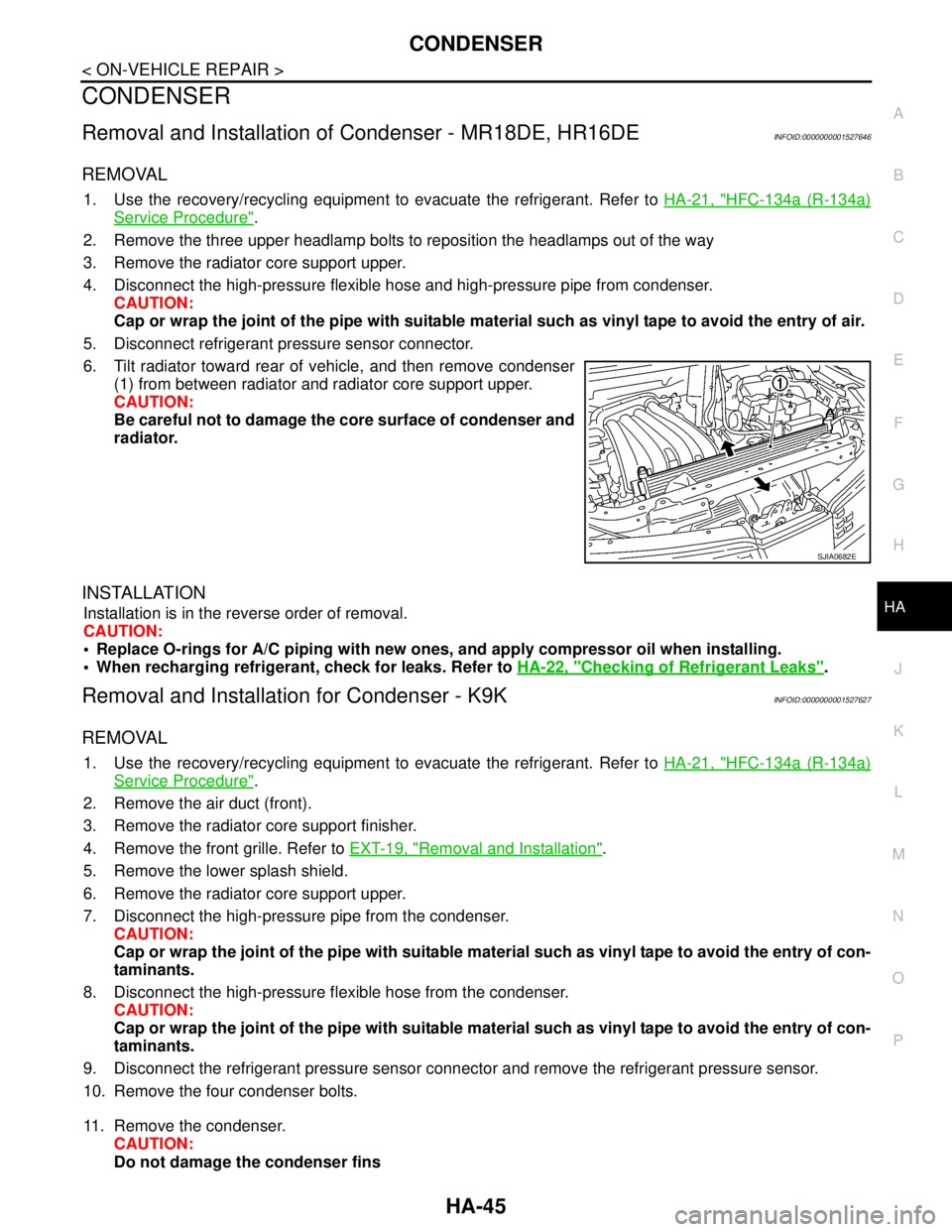
6. Tilt radiator toward rear of vehicle, and then remove condenser
(1) from between radiator and radiator core support upper.
CAUTION:
Be careful not to damage the core surface of condenser and
radiator.
INSTALLATION
Installation is in the reverse order of removal.
CAUTION:
Replace O-rings for A/C piping with new ones, and apply compressor oil when installing.
When recharging refrigerant, check for leaks. Refer to HA-22, "
Checking of Refrigerant Leaks".
Removal and Installation for Condenser - K9KINFOID:0000000001527627
REMOVAL
1. Use the recovery/recycling equipment to evacuate the refrigerant. Refer to HA-21, "HFC-134a (R-134a)
Service Procedure".
2. Remove the air duct (front).
3. Remove the radiator core support finisher.
4. Remove the front grille. Refer to EXT-19, "
Removal and Installation".
5. Remove the lower splash shield.
6. Remove the radiator core support upper.
7. Disconnect the high-pressure pipe from the condenser.
CAUTION:
Cap or wrap the joint of the pipe with suitable material such as vinyl tape to avoid the entry of con-
taminants.
8. Disconnect the high-pressure flexible hose from the condenser.
CAUTION:
Cap or wrap the joint of the pipe with suitable material such as vinyl tape to avoid the entry of con-
taminants.
9. Disconnect the refrigerant pressure sensor connector and remove the refrigerant pressure sensor.
10. Remove the four condenser bolts.
11. Remove the condenser.
CAUTION:
Do not damage the condenser fins
SJIA0682E
Page 3328 of 5883
HA-46
< ON-VEHICLE REPAIR >
CONDENSER
INSTALLATION
Installation is in the reverse order of removal.
CAUTION:
Do not damage the condenser fins.
Replace O-rings of the high-pressure pipe, high-pressure flexible hose and refrigerant pressure sen-
sor with new ones, and apply compressor oil when installing.
When charging the refrigerant, check for leaks. Refer to HA-22, "
Checking of Refrigerant Leaks".
Page 3330 of 5883

HA-48
< ON-VEHICLE REPAIR >
REFRIGERANT PRESSURE SENSOR
REFRIGERANT PRESSURE SENSOR
Removal and Installation of Refrigerant Pressure Sensor - MR18DE, HR16DE
INFOID:0000000001527644
REMOVAL
1. Use the recovery/recycling equipment to evacuate the refrigerant. Refer to HA-21, "HFC-134a (R-134a)
Service Procedure".
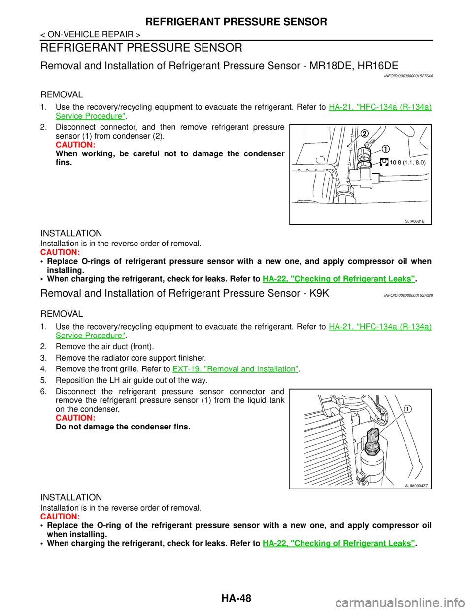
2. Disconnect connector, and then remove refrigerant pressure
sensor (1) from condenser (2).
CAUTION:
When working, be careful not to damage the condenser
fins.
INSTALLATION
Installation is in the reverse order of removal.
CAUTION:
Replace O-rings of refrigerant pressure sensor with a new one, and apply compressor oil when
installing.
When charging the refrigerant, check for leaks. Refer to HA-22, "
Checking of Refrigerant Leaks".
Removal and Installation of Refrigerant Pressure Sensor - K9KINFOID:0000000001527628
REMOVAL
1. Use the recovery/recycling equipment to evacuate the refrigerant. Refer to HA-21, "HFC-134a (R-134a)
Service Procedure".
2. Remove the air duct (front).
3. Remove the radiator core support finisher.
4. Remove the front grille. Refer to EXT-19, "
Removal and Installation".
5. Reposition the LH air guide out of the way.
6. Disconnect the refrigerant pressure sensor connector and
remove the refrigerant pressure sensor (1) from the liquid tank
on the condenser.
CAUTION:
Do not damage the condenser fins.
INSTALLATION
Installation is in the reverse order of removal.
CAUTION:
Replace the O-ring of the refrigerant pressure sensor with a new one, and apply compressor oil
when installing.
When charging the refrigerant, check for leaks. Refer to HA-22, "
Checking of Refrigerant Leaks".
SJIA0681E
ALIIA0004ZZ
Page 3331 of 5883

EXPANSION VALVE
HA-49
< ON-VEHICLE REPAIR >
C
D
E
F
G
H
J
K
L
MA
B
HA
N
O
P
EXPANSION VALVE
Removal and Installation of Expansion Valve - MR18DE, HR16DE and K9K
INFOID:0000000001527645
REMOVAL
1. Use the recovery/recycling equipment to evacuate the refrigerant. Refer to HA-21, "HFC-134a (R-134a)
Service Procedure".
2. Remove cowl top cover. Refer to EXT-20, "
Removal and Installation".
3. Remove lower dash insulator.
4. Disconnect low-pressure flexible hose and high-pressure pipe from evaporator. Refer to HA-27, "
Compo-
nent".
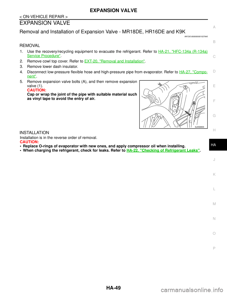
5. Remove expansion valve bolts (A), and then remove expansion
valve (1).
CAUTION:
Cap or wrap the joint of the pipe with suitable material such
as vinyl tape to avoid the entry of air.
INSTALLATION
Installation is in the reverse order of removal.
CAUTION:
Replace O-rings of evaporator with new ones, and apply compressor oil when installing.
When charging the refrigerant, check for leaks. Refer to HA-22, "
Checking of Refrigerant Leaks".
SJIA0683E
Page 3332 of 5883

HA-50
< SERVICE DATA AND SPECIFICATIONS (SDS)
SERVICE DATA AND SPECIFICATIONS (SDS)
SERVICE DATA AND SPECIFICATIONS (SDS)
SERVICE DATA AND SPECIFICATIONS (SDS)
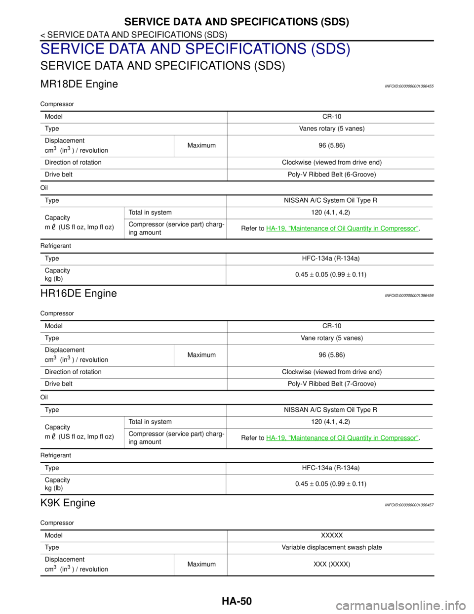
MR18DE EngineINFOID:0000000001396455
Compressor
Oil
Refrigerant
HR16DE EngineINFOID:0000000001396456
Compressor
Oil
Refrigerant
K9K EngineINFOID:0000000001396457
Compressor
ModelCR-10
Ty p eVanes rotary (5 vanes)
Displacement
cm
3 (in3 ) / revolutionMaximum 96 (5.86)
Direction of rotation Clockwise (viewed from drive end)
Drive beltPoly-V Ribbed Belt (6-Groove)
Ty p eNISSAN A/C System Oil Type R
Capacity
m (US fl oz, lmp fl oz)Total in system 120 (4.1, 4.2)
Compressor (service part) charg-
ing amountRefer to HA-19, "
Maintenance of Oil Quantity in Compressor".
Ty p eHFC-134a (R-134a)
Capacity
kg (lb)0.45 ± 0.05 (0.99 ± 0.11)
ModelCR-10
Ty p eVane rotary (5 vanes)
Displacement
cm
3 (in3 ) / revolutionMaximum 96 (5.86)
Direction of rotation Clockwise (viewed from drive end)
Drive beltPoly-V Ribbed Belt (7-Groove)
Ty p eNISSAN A/C System Oil Type R
Capacity
m (US fl oz, lmp fl oz)Total in system 120 (4.1, 4.2)
Compressor (service part) charg-
ing amountRefer to HA-19, "
Maintenance of Oil Quantity in Compressor".
Ty p eHFC-134a (R-134a)
Capacity
kg (lb)0.45 ± 0.05 (0.99 ± 0.11)
ModelXXXXX
Ty p eVariable displacement swash plate
Displacement
cm
3 (in3 ) / revolutionMaximum XXX (XXXX)
Page 3333 of 5883
SERVICE DATA AND SPECIFICATIONS (SDS)
HA-51
< SERVICE DATA AND SPECIFICATIONS (SDS)
C
D
E
F
G
H
J
K
L
MA
B
HA
N
O
P
Oil
Refrigerant
Direction of rotation Clockwise (viewed from drive end)
Drive beltPoly-V Ribbed Belt (6-Groove)
Typ eNISSAN A/C System Oil Type S
Capacity
m (US fl oz, lmp fl oz)Total in system 100 (3.4, 3.5)
Compressor (service part) charg-
ing amountRefer to HA-19, "
Maintenance of Oil Quantity in Compressor".
Typ eHFC-134a (R-134a)
Capacity
kg (lb)0.45 ± 0.05 (0.99 ± 0.11)
Page 3411 of 5883
![NISSAN TIIDA 2007 Service Repair Manual HAC-78
< SYMPTOM DIAGNOSIS >[MANUAL AIR CONDITIONER]
INSUFFICIENT COOLING
High-pressure Side is Too High and Low-pressure Side is Too Low
High-pressure Side is Too Low and Low-pressure Side is Too Hig NISSAN TIIDA 2007 Service Repair Manual HAC-78
< SYMPTOM DIAGNOSIS >[MANUAL AIR CONDITIONER]
INSUFFICIENT COOLING
High-pressure Side is Too High and Low-pressure Side is Too Low
High-pressure Side is Too Low and Low-pressure Side is Too Hig](/manual-img/5/57395/w960_57395-3410.png)
HAC-78
< SYMPTOM DIAGNOSIS >[MANUAL AIR CONDITIONER]
INSUFFICIENT COOLING
High-pressure Side is Too High and Low-pressure Side is Too Low
High-pressure Side is Too Low and Low-pressure Side is Too High
Both High- and Low-pressure Sides are Too Low
Gauge indication Refrigerant cycle Probable cause Corrective action
Both high- and low-pressure
sides are too high.Pressure is reduced soon af-
ter water is splashed on con-
denser.Excessive refrigerant charge in refrig-
eration cycle.Reduce refrigerant until
specified pressure is ob-
tained.
Air suction by cooling fan is in-
sufficient.Insufficient condenser cooling perfor-
mance.
↓
1. Condenser fins are clogged.
2. Improper fan rotation of cooling
fan. Clean condenser.
Check and repair cooling
fan if necessary.
Low-pressure pipe is not
cold.
When compressor is
stopped high-pressure val-
ue quickly drops by approx-
imately 196 kPa (1.96 bar, 2
kg/cm
2 , 28 psi). It then de-
creases gradually thereaf-
ter.Poor heat exchange in condenser
(After compressor operation stops,
high-pressure decreases too slowly.).
↓
Air in refrigeration cycle.Evacuate repeatedly and
recharge system.
Engine tends to overheat. Engine cooling systems malfunction.Check and repair each en-
gine cooling system.
An area of the low-pressure
pipe is colder than areas
near the evaporator outlet.
Plates are sometimes cov-
ered with frost. Excessive liquid refrigerant on low-
pressure side.
Excessive refrigerant discharge
flow.
Expansion valve is open a little
compared with the specification.
↓
Improper expansion valve adjust-
ment.Replace expansion valve.
AC359A
Gauge indication Refrigerant cycle Probable cause Corrective action
High-pressure side is too high
and low-pressure side is too low.
Upper side of condenser and
high-pressure side are hot,
however, liquid tank is not so
hot.High-pressure tube or parts located
between compressor and condenser
are clogged or crushed. Check and repair or re-
place malfunctioning
parts.
Check oil for contami-
nation.
AC360A
Gauge indication Refrigerant cycle Probable cause Corrective action
High-pressure side is too low
and low-pressure side is too
high.High- and low-pressure sides
become equal soon after com-
pressor operation stops.Compressor pressure operation
is improper.
↓
Damaged inside compressor
packings.Replace compressor.
No temperature difference be-
tween high- and low-pressure
sides.Compressor pressure operation
is improper.
↓
Damaged inside compressor
packings.Replace compressor.
AC356A