2007 NISSAN TIIDA light
[x] Cancel search: lightPage 5717 of 5883

WCS-2
BCM (BODY CONTROL MODULE) .........................21
BCM (BODY CONTROL MODULE) : Diagnosis
Procedure ...............................................................
21
METER BUZZER CIRCUIT ................................23
Description ..............................................................23
Component Function Check ...................................23
Diagnosis Procedure .............................................23
SEAT BELT BUCKLE SWITCH SIGNAL CIR-
CUIT ...................................................................
24
Description ..............................................................24
Component Function Check .................................24
Diagnosis Procedure .............................................24
Component Inspection ............................................25
KEY SWITCH SIGNAL CIRCUIT (WITH IN-
TELLIGENT KEY) ..............................................
26
Description ..............................................................26
Component Function Check .................................26
Diagnosis Procedure .............................................26
Component Inspection ............................................27
KEY SWITCH SIGNAL CIRCUIT (WITHOUT
INTELLIGENT KEY) ..........................................
28
Description ..............................................................28
Component Function Check .................................28
Diagnosis Procedure .............................................28
Component Inspection ............................................29
PARKING BRAKE SWITCH SIGNAL CIR-
CUIT ...................................................................
30
Description ..............................................................30
Component Function Check ...................................30
Diagnosis Procedure ..............................................30
Component Inspection ............................................30
WARNING CHIME SYSTEM .............................31
Wiring Diagram .......................................................31
ECU DIAGNOSIS ........................................37
COMBINATION METER ....................................37
Reference Value .....................................................37
Wiring Diagram .......................................................40
Fail Safe ..................................................................54
DTC Index ...............................................................55
BCM (BODY CONTROL MODULE) ..................56
Reference Value .....................................................56
Terminal Layout ......................................................59
Physical Values .......................................................59
Wiring Diagram .......................................................71
DTC Inspection Priority Chart ...............................74
DTC Index ..............................................................75
SYMPTOM DIAGNOSIS ............................76
THE LIGHT REMINDER WARNING DOES
NOT SOUND ......................................................
76
Description ..............................................................76
Diagnosis Procedure ...............................................76
THE SEAT BELT WARNING CONTINUES
SOUNDING, OR DOES NOT SOUND ...............
77
Description ..............................................................77
Diagnosis Procedure ...............................................77
THE KEY WARNING DOES NOT SOUND .......78
Description ..............................................................78
Diagnosis Procedure ...............................................78
THE PARKING BRAKE RELEASE WARNING
CONTINUES SOUNDING, OR DOES NOT
SOUND ..............................................................
79
Description ..............................................................79
Diagnosis Procedure ...............................................79
PRECAUTION ............................................80
PRECAUTIONS .................................................80
Supplemental Restraint System (SRS) "AIR BAG"
and "SEAT BELT PRE-TENSIONER" ....................
80
Page 5719 of 5883
WCS-4
< FUNCTION DIAGNOSIS >
WARNING CHIME SYSTEM
FUNCTION DIAGNOSIS
WARNING CHIME SYSTEM
WARNING CHIME SYSTEM
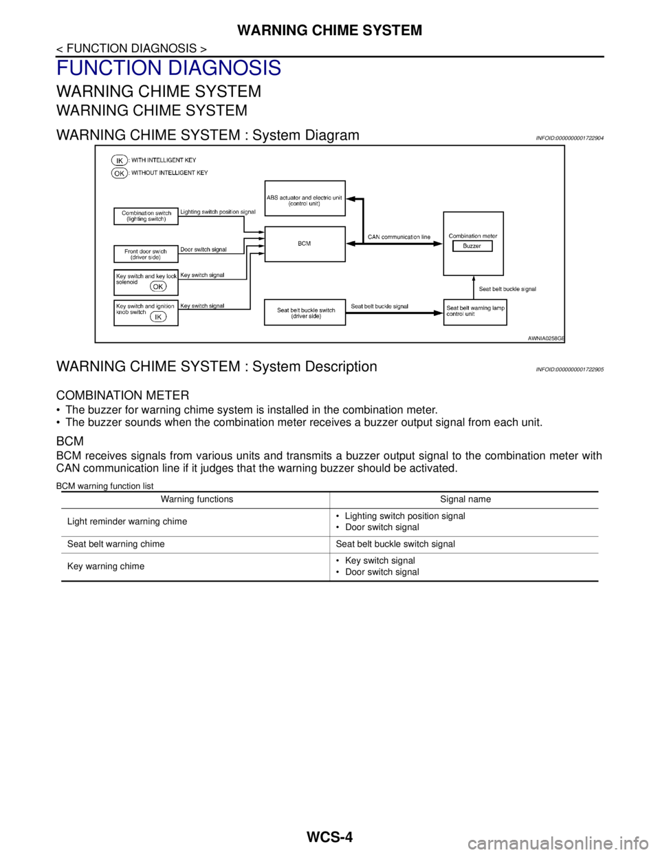
WARNING CHIME SYSTEM : System DiagramINFOID:0000000001722904
WARNING CHIME SYSTEM : System DescriptionINFOID:0000000001722905
COMBINATION METER
The buzzer for warning chime system is installed in the combination meter.
The buzzer sounds when the combination meter receives a buzzer output signal from each unit.
BCM
BCM receives signals from various units and transmits a buzzer output signal to the combination meter with
CAN communication line if it judges that the warning buzzer should be activated.
BCM warning function list
AWNIA0258GB
Warning functions Signal name
Light reminder warning chime Lighting switch position signal
Door switch signal
Seat belt warning chime Seat belt buckle switch signal
Key warning chime Key switch signal
Door switch signal
Page 5720 of 5883
WCS
WARNING CHIME SYSTEM
WCS-5
< FUNCTION DIAGNOSIS >
C
D
E
F
G
H
I
J
K
L
MB A
O
P
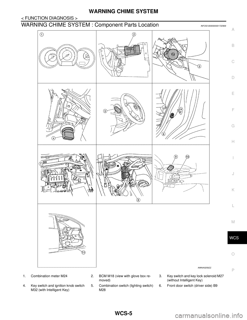
WARNING CHIME SYSTEM : Component Parts LocationINFOID:0000000001722906
AWNIA0259ZZ
1. Combination meter M24 2. BCM M18 (view with glove box re-
moved)3. Key switch and key lock solenoid M27
(without Intelligent Key)
4. Key switch and ignition knob switch
M32 (with Intelligent Key)5. Combination switch (lighting switch)
M286. Front door switch (driver side) B9
Page 5721 of 5883
WCS-6
< FUNCTION DIAGNOSIS >
WARNING CHIME SYSTEM
WARNING CHIME SYSTEM : Component Description
INFOID:0000000001722907
LIGHT REMINDER WARNING CHIME
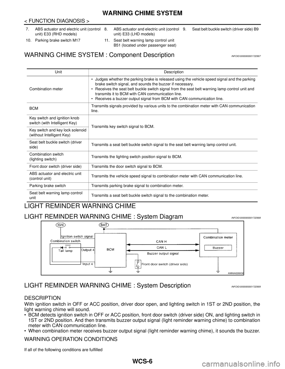
LIGHT REMINDER WARNING CHIME : System DiagramINFOID:0000000001722908
LIGHT REMINDER WARNING CHIME : System DescriptionINFOID:0000000001722909
DESCRIPTION
With ignition switch in OFF or ACC position, driver door open, and lighting switch in 1ST or 2ND position, the
light warning chime will sound.
BCM detects ignition switch in OFF or ACC position, front door switch (driver side) ON, and lighting switch in
1ST or 2ND position. And then transmits buzzer output signal (light reminder warning chime) to combination
meter with CAN communication line.
When combination meter receives buzzer output signal (light reminder warning chime), it sounds the buzzer.
WARNING OPERATION CONDITIONS
If all of the following conditions are fulfilled
7. ABS actuator and electric unit (control
unit) E33 (RHD models)8. ABS actuator and electric unit (control
unit) E33 (LHD models)9. Seat belt buckle switch (driver side) B9
10. Parking brake switch M17 11. Seat belt warning lamp control unit
B51 (located under passenger seat)
Unit Description
Combination meter Judges whether the parking brake is released using the vehicle speed signal and the parking
brake switch signal, and sounds the buzzer if necessary.
Receives the seat belt buckle switch signal from the seat belt warning lamp control unit and
transmits it to BCM with CAN communication line.
Receives a buzzer output signal from BCM with CAN communication line.
BCMTransmits signals provided by various units to the combination meter with CAN communication
line.
Key switch and ignition knob
switch (with Intelligent Key)
Transmits key switch signal to BCM.
Key switch and key lock solenoid
(without Intelligent Key)
Seat belt buckle switch (driver
side)Transmits a seat belt buckle switch signal to the seat belt warning lamp control unit.
Combination switch
(lighting switch)Transmits the lighting switch position signal to BCM.
Front door switch (driver side) Transmits the door switch signal to BCM.
ABS actuator and electric unit
(control unit)Transmits the vehicle speed signal to combination meter with CAN communication line.
Parking brake switch Transmits parking brake signal to combination meter.
Seat belt warning lamp control
unitTransmits a seat belt buckle switch signal to the combination meter.
AWNIA0260GB
Page 5722 of 5883
WCS
WARNING CHIME SYSTEM
WCS-7
< FUNCTION DIAGNOSIS >
C
D
E
F
G
H
I
J
K
L
MB A
O
P
Lighting switch is at 1st or 2nd position
Ignition switch is at OFF or ACC
Front door switch (driver side) is ON
WARNING CANCEL CONDITIONS
Warning is canceled if any of the following conditions is fulfilled. Lighting switch OFF
Ignition switch ON
Front door switch (driver side) is OFF
Page 5723 of 5883
WCS-8
< FUNCTION DIAGNOSIS >
WARNING CHIME SYSTEM
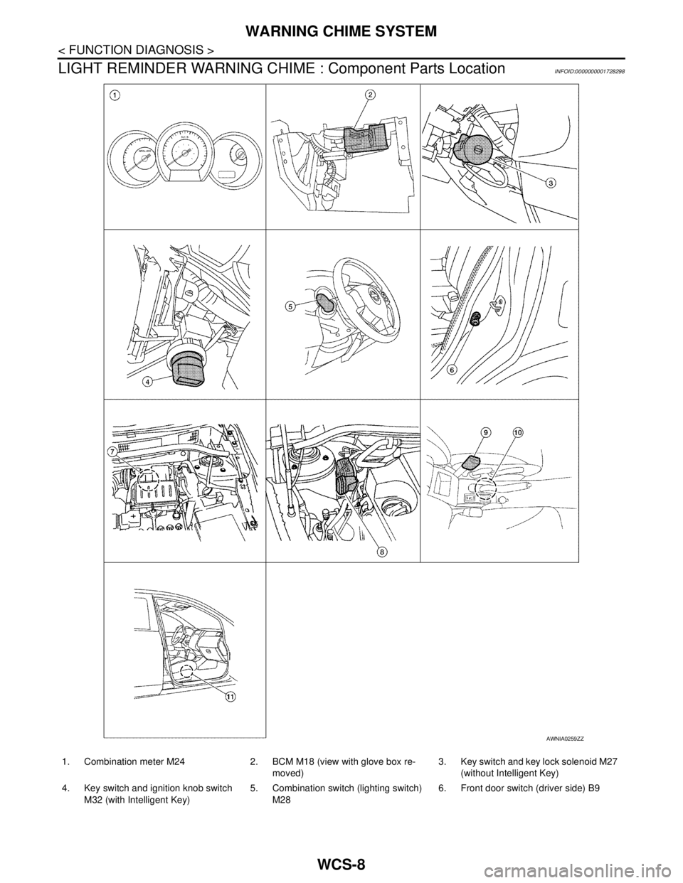
LIGHT REMINDER WARNING CHIME : Component Parts Location
INFOID:0000000001728298
AWNIA0259ZZ
1. Combination meter M24 2. BCM M18 (view with glove box re-
moved)3. Key switch and key lock solenoid M27
(without Intelligent Key)
4. Key switch and ignition knob switch
M32 (with Intelligent Key)5. Combination switch (lighting switch)
M286. Front door switch (driver side) B9
Page 5724 of 5883
WCS
WARNING CHIME SYSTEM
WCS-9
< FUNCTION DIAGNOSIS >
C
D
E
F
G
H
I
J
K
L
MB A
O
P
LIGHT REMINDER WARNING CHIME : Component DescriptionINFOID:0000000001722911
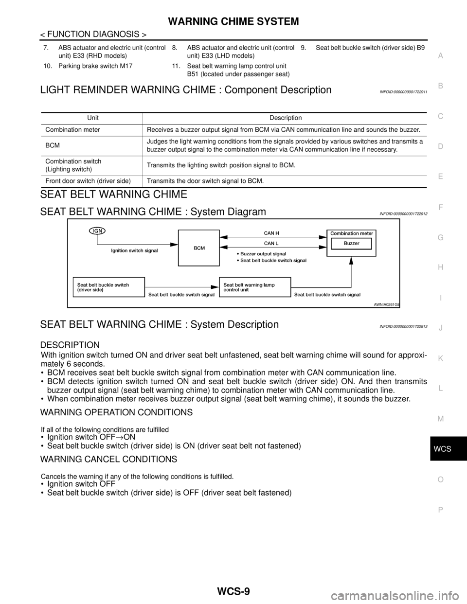
SEAT BELT WARNING CHIME
SEAT BELT WARNING CHIME : System DiagramINFOID:0000000001722912
SEAT BELT WARNING CHIME : System DescriptionINFOID:0000000001722913
DESCRIPTION
With ignition switch turned ON and driver seat belt unfastened, seat belt warning chime will sound for approxi-
mately 6 seconds.
BCM receives seat belt buckle switch signal from combination meter with CAN communication line.
BCM detects ignition switch turned ON and seat belt buckle switch (driver side) ON. And then transmits
buzzer output signal (seat belt warning chime) to combination meter with CAN communication line.
When combination meter receives buzzer output signal (seat belt warning chime), it sounds the buzzer.
WARNING OPERATION CONDITIONS
If all of the following conditions are fulfilled
Ignition switch OFF→ON
Seat belt buckle switch (driver side) is ON (driver seat belt not fastened)
WARNING CANCEL CONDITIONS
Cancels the warning if any of the following conditions is fulfilled.
Ignition switch OFF
Seat belt buckle switch (driver side) is OFF (driver seat belt fastened)
7. ABS actuator and electric unit (control
unit) E33 (RHD models)8. ABS actuator and electric unit (control
unit) E33 (LHD models)9. Seat belt buckle switch (driver side) B9
10. Parking brake switch M17 11. Seat belt warning lamp control unit
B51 (located under passenger seat)
Unit Description
Combination meter Receives a buzzer output signal from BCM via CAN communication line and sounds the buzzer.
BCMJudges the light warning conditions from the signals provided by various switches and transmits a
buzzer output signal to the combination meter via CAN communication line if necessary.
Combination switch
(Lighting switch)Transmits the lighting switch position signal to BCM.
Front door switch (driver side) Transmits the door switch signal to BCM.
AWNIA0261GB
Page 5725 of 5883
WCS-10
< FUNCTION DIAGNOSIS >
WARNING CHIME SYSTEM
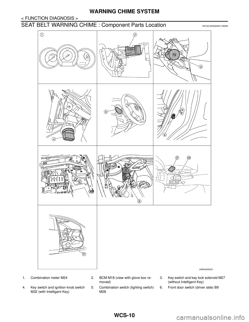
SEAT BELT WARNING CHIME : Component Parts Location
INFOID:0000000001728299
AWNIA0259ZZ
1. Combination meter M24 2. BCM M18 (view with glove box re-
moved)3. Key switch and key lock solenoid M27
(without Intelligent Key)
4. Key switch and ignition knob switch
M32 (with Intelligent Key)5. Combination switch (lighting switch)
M286. Front door switch (driver side) B9