2007 NISSAN TIIDA Abs CAN line
[x] Cancel search: Abs CAN linePage 2629 of 5883
![NISSAN TIIDA 2007 Service Repair Manual EC-1280
< SYMPTOM DIAGNOSIS >[K9K]
OVERSPEED AT IDLE SPEED OR ON RELEASING BRAKE
OVERSPEED AT IDLE SPEED OR ON RELEASING BRAKE
DescriptionINFOID:0000000001162725
CHART 14: OVERSPEED AT IDLE SPEED OR O](/manual-img/5/57395/w960_57395-2628.png "NISSAN TIIDA 2007 Service Repair Manual EC-1280
< SYMPTOM DIAGNOSIS >[K9K]
OVERSPEED AT IDLE SPEED OR ON RELEASING BRAKE
OVERSPEED AT IDLE SPEED OR ON RELEASING BRAKE
DescriptionINFOID:0000000001162725
CHART 14: OVERSPEED AT IDLE SPEED OR O")
EC-1280
< SYMPTOM DIAGNOSIS >[K9K]
OVERSPEED AT IDLE SPEED OR ON RELEASING BRAKE
OVERSPEED AT IDLE SPEED OR ON RELEASING BRAKE
DescriptionINFOID:0000000001162725
CHART 14: OVERSPEED AT IDLE SPEED OR ON RELEASING BRAKE
Diagnosis ProcedureINFOID:0000000001162726
1.CHECK ENGINE OIL
Check the grade of engine oil. Refer to LU-26, "
Inspection".
Is the inspection result normal?
YES >> GO TO 2.
NO >> Replace engine oil. Refer to LU-27, "
Refilling"
2.CHECK ENGINE OIL LEVEL
Is the engine oil level correct?
Ye s o r N o
Ye s > > G O T O 3 .
No >> Top up the oil.
3.CHECK ECM POWER SUPPLY AND GROUND CIRCUIT
Check ECM power supply and ground circuit. Refer to EC-1106, "
Diagnosis Procedure".
Is the inspection result normal?
YES >> GO TO 4.
NO >> Repair or replace harness or connector.
4.CHECK WIRING HARNESS
Visually check the condition of the engine wiring harness.
Is the inspection result normal?
YES >> GO TO 5.
NO >> Repair or replace harness or connector.
5.CHECK CAN COMMUNICATION
Perform trouble diagnosis on the CAN communication line using CONSULT-III. Refer to LAN-33, "
CAN Com-
munication Signal Chart".
Is the inspection result normal?
YES >> GO TO 6.
NO >> Repair or replace harness or connector.
6.CHECK “ABS ACTUATOR AND ELECTRIC UNIT (CONTROL UNIT)”
Perform trouble diagnosis on the “ABS ACTUATOR AND ELECTRIC UNIT (CONTROL UNIT)”. Refer to BRC-
25, "CONSULT-III Function (ABS)" (without ESP) or BRC-105, "CONSULT-III Function (ABS)" (with ESP).
Is the inspection result normal?
YES >> INSPECTION END.
NO >> Repair or replace.
Page 3166 of 5883
FL-6
< ON-VEHICLE REPAIR >
FUEL LEVEL SENSOR UNIT, FUEL FILTER AND FUEL PUMP ASSEMBLY
b. Disconnect fuel filler hose from fuel filler tube. Refer to FL-10, "HR16DE, HR18DE".
c. Insert fuel tubing into fuel tank through fuel filler hose to drain fuel from fuel tank.
2. Release the fuel pressure from the fuel lines. Refer to EC-377, "
Inspection" (HR16DE with EURO-OBD),
EC-681, "
Inspection" (HR16DE without EURO-OBD), EC-1035, "Inspection" (MR18DE).
3. Open fuel filler lid.
4. Open fuel door and unscrew the fuel filler cap to release the pressure inside the fuel tank.
5. Remove rear seat bottom. Refer to SE-18, "
Removal and Installation".
6. Turn the four retainers 90° in a clockwise direction and remove the fuel pump inspection hole cover.
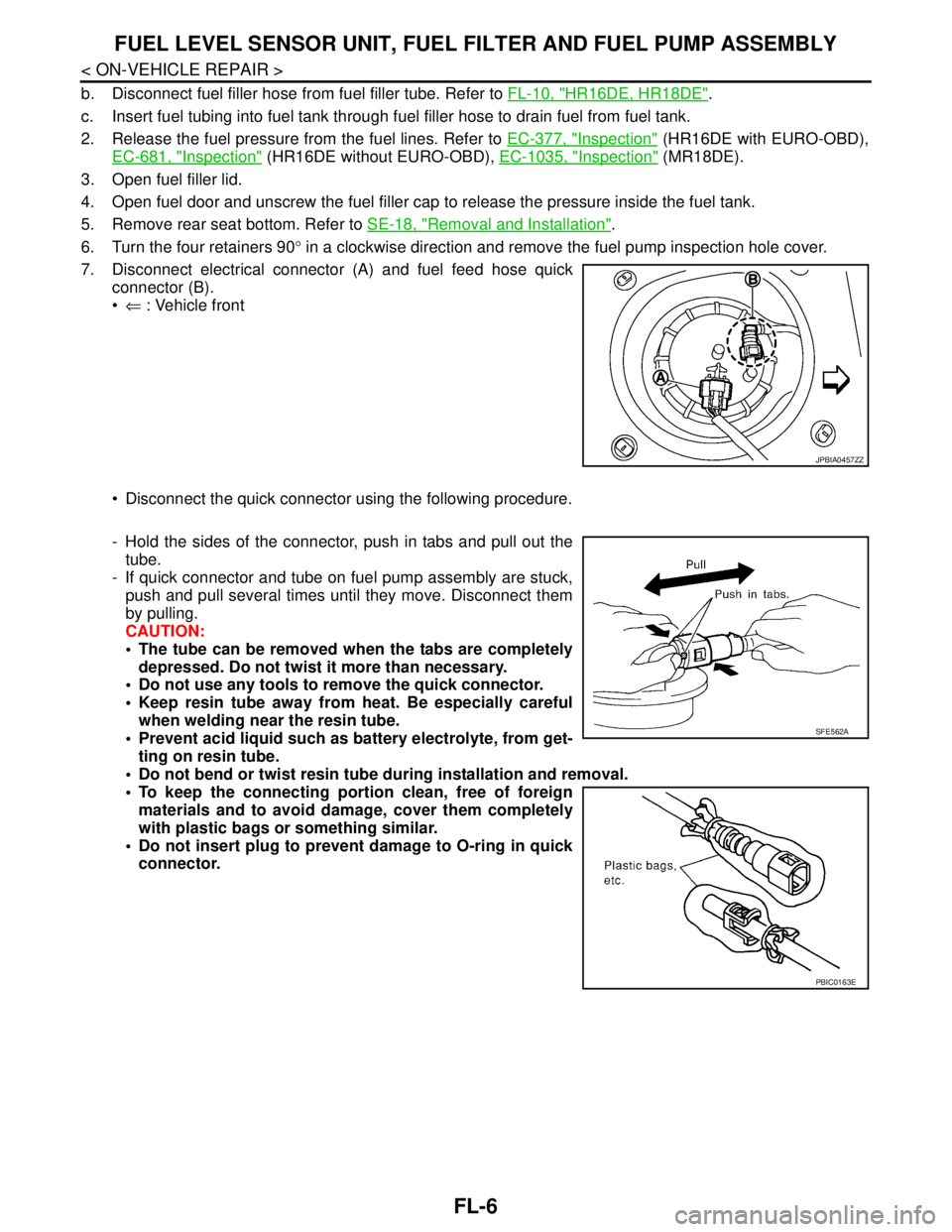
7. Disconnect electrical connector (A) and fuel feed hose quick
connector (B).
⇐ : Vehicle front
Disconnect the quick connector using the following procedure.
- Hold the sides of the connector, push in tabs and pull out the
tube.
- If quick connector and tube on fuel pump assembly are stuck,
push and pull several times until they move. Disconnect them
by pulling.
CAUTION:
The tube can be removed when the tabs are completely
depressed. Do not twist it more than necessary.
Do not use any tools to remove the quick connector.
Keep resin tube away from heat. Be especially careful
when welding near the resin tube.
Prevent acid liquid such as battery electrolyte, from get-
ting on resin tube.
Do not bend or twist resin tube during installation and removal.
To keep the connecting portion clean, free of foreign
materials and to avoid damage, cover them completely
with plastic bags or something similar.
Do not insert plug to prevent damage to O-ring in quick
connector.
JPBIA0457ZZ
SFE562A
PBIC0163E
Page 3257 of 5883
CONSULT-III CHECKING SYSTEM
GI-63
< BASIC INSPECTION >
C
D
E
F
G
H
I
J
K
L
MB
GI
N
O
PCONSULT-III CHECKING SYSTEM
DescriptionINFOID:0000000001691472
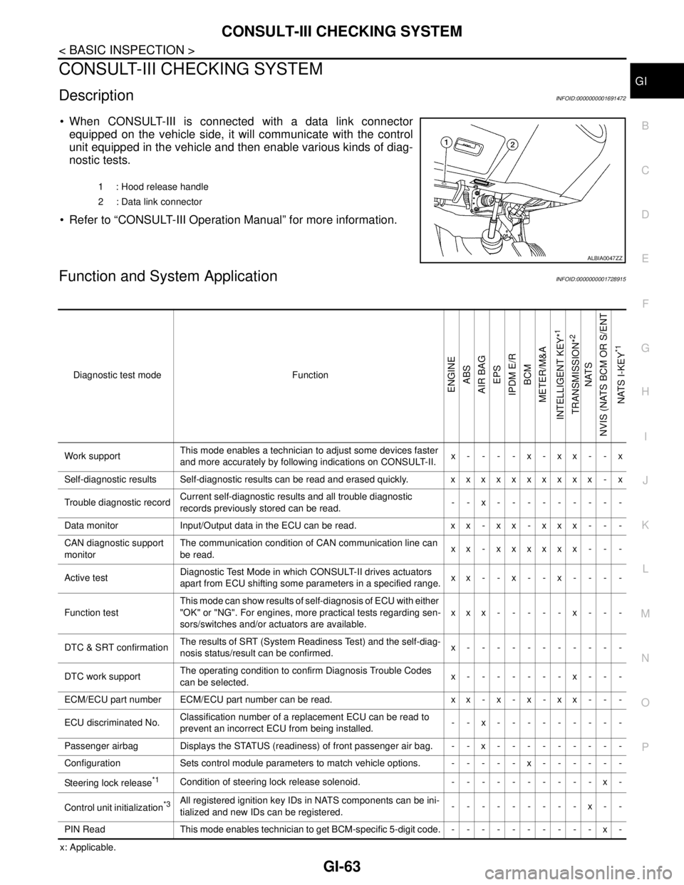
When CONSULT-III is connected with a data link connector
equipped on the vehicle side, it will communicate with the control
unit equipped in the vehicle and then enable various kinds of diag-
nostic tests.
Refer to “CONSULT-III Operation Manual” for more information.
Function and System ApplicationINFOID:0000000001728915
x: Applicable.1 : Hood release handle
2 : Data link connector
ALBIA0047ZZ
Diagnostic test mode Function
ENGINE
ABS
AIR BAG
EPS
IPDM E/R
BCM
METER/M&A
INTELLIGENT KEY*
1
TRANSMISSION*
2
NATS
NVIS (NATS BCM OR S/ENT
NATS I-KEY
*1
Work supportThis mode enables a technician to adjust some devices faster
and more accurately by following indications on CONSULT-II.x----x-xx--x
Self-diagnostic results Self-diagnostic results can be read and erased quickly. xxxxxxxxxx - x
Trouble diagnostic recordCurrent self-diagnostic results and all trouble diagnostic
records previously stored can be read.--x---------
Data monitor Input/Output data in the ECU can be read. x x - x x - x x x - - -
CAN diagnostic support
monitorThe communication condition of CAN communication line can
be read.xx - xxxxxx - - -
Active testDiagnostic Test Mode in which CONSULT-II drives actuators
apart from ECU shifting some parameters in a specified range.xx--x--x----
Function testThis mode can show results of self-diagnosis of ECU with either
"OK" or "NG". For engines, more practical tests regarding sen-
sors/switches and/or actuators are available.xxx-----x---
DTC & SRT confirmationThe results of SRT (System Readiness Test) and the self-diag-
nosis status/result can be confirmed.x-----------
DTC work supportThe operating condition to confirm Diagnosis Trouble Codes
can be selected.x-------x---
ECM/ECU part number ECM/ECU part number can be read. x x - x - x - x x - - -
ECU discriminated No.Classification number of a replacement ECU can be read to
prevent an incorrect ECU from being installed.--x---------
Passenger airbag Displays the STATUS (readiness) of front passenger air bag. --x---------
Configuration Sets control module parameters to match vehicle options. -----x------
Steering lock release
*1Condition of steering lock release solenoid. ----------x-
Control unit initialization
*3All registered ignition key IDs in NATS components can be ini-
tialized and new IDs can be registered.---------x--
PIN Read This mode enables technician to get BCM-specific 5-digit code.----------x-
Page 3741 of 5883

LAN
LAN-1
ELECTRICAL & POWER CONTROL
C
D
E
F
G
H
I
J
K
L B
SECTION LAN
A
O
P N
CONTENTS
LAN SYSTEM
CAN FUNDAMENTAL
PRECAUTION ..............................................
12
PRECAUTIONS ..................................................12
Precautions for Trouble Diagnosis ..........................12
Precautions for Harness Repair ..............................12
FUNCTION DIAGNOSIS ..............................13
CAN COMMUNICATION SYSTEM ....................13
System Description .................................................13
System Diagram ......................................................13
CAN Communication Control Circuit .......................14
DIAG ON CAN ....................................................15
Description ..............................................................15
System Diagram ......................................................15
TROUBLE DIAGNOSIS .....................................16
Condition of Error Detection ....................................16
Symptom When Error Occurs in CAN Communi-
cation System ..........................................................
16
CAN Diagnosis with CONSULT-III ..........................19
Self-Diagnosis .........................................................19
CAN Diagnostic Support Monitor ............................19
How to Use CAN Communication Signal Chart ......21
BASIC INSPECTION ...................................22
DIAGNOSIS AND REPAIR WORKFLOW .........22
Trouble Diagnosis Flow Chart .................................22
Trouble Diagnosis Procedure ..................................22
CAN
HOW TO USE THIS MANUAL .....................
27
HOW TO USE THIS SECTION ...........................27
Caution ....................................................................27
Abbreviation List ......................................................27
PRECAUTION ..............................................28
PRECAUTIONS .................................................28
Precaution for Supplemental Restraint System
(SRS) "AIR BAG" and "SEAT BELT PRE-TEN-
SIONER" .................................................................
28
Precautions for Trouble Diagnosis ..........................28
Precautions for Harness Repair ..............................28
BASIC INSPECTION ...................................29
DIAGNOSIS AND REPAIR WORKFLOW ........29
Interview Sheet ........................................................29
FUNCTION DIAGNOSIS ..............................30
CAN COMMUNICATION SYSTEM ...................30
CAN System Specification Chart .............................30
CAN Communication Signal Chart ..........................33
COMPONENT DIAGNOSIS .........................36
CAN COMMUNICATION SYSTEM ...................36
Component Parts Location ......................................36
Wiring Diagram - CAN SYSTEM - ...........................38
MALFUNCTION AREA CHART ........................42
Main Line .................................................................42
Branch Line .............................................................42
Short Circuit .............................................................42
MAIN LINE BETWEEN DLC AND ABS CIR-
CUIT ..................................................................
43
Diagnosis Procedure ...............................................43
MAIN LINE BETWEEN DLC AND AV CIR-
CUIT ..................................................................
44
Diagnosis Procedure ...............................................44
MAIN LINE BETWEEN AV AND ABS CIR-
CUIT ..................................................................
45
Diagnosis Procedure ...............................................45
ECM BRANCH LINE CIRCUIT .........................47
Diagnosis Procedure ...............................................47
Page 3742 of 5883

LAN-2
BCM BRANCH LINE CIRCUIT ..........................48
Diagnosis Procedure ..............................................48
DLC BRANCH LINE CIRCUIT ...........................49
Diagnosis Procedure ..............................................49
EPS BRANCH LINE CIRCUIT ...........................50
Diagnosis Procedure ..............................................50
I-KEY BRANCH LINE CIRCUIT ........................51
Diagnosis Procedure ..............................................51
M&A BRANCH LINE CIRCUIT ..........................52
Diagnosis Procedure ..............................................52
STRG BRANCH LINE CIRCUIT ........................53
Diagnosis Procedure ..............................................53
AV BRANCH LINE CIRCUIT .............................54
Diagnosis Procedure ..............................................54
ABS BRANCH LINE CIRCUIT ..........................55
Diagnosis Procedure ..............................................55
TCM BRANCH LINE CIRCUIT ..........................56
Diagnosis Procedure ..............................................56
IPDM-E BRANCH LINE CIRCUIT .....................57
Diagnosis Procedure ..............................................57
CAN COMMUNICATION CIRCUIT ....................58
Diagnosis Procedure ..............................................58
CAN SYSTEM (TYPE 1)
COMPONENT DIAGNOSIS ........................
60
MAIN LINE BETWEEN DLC AND ABS CIR-
CUIT ...................................................................
60
Diagnosis Procedure ..............................................60
ECM BRANCH LINE CIRCUIT ..........................61
Diagnosis Procedure ..............................................61
BCM BRANCH LINE CIRCUIT ..........................62
Diagnosis Procedure ..............................................62
DLC BRANCH LINE CIRCUIT ...........................63
Diagnosis Procedure ..............................................63
EPS BRANCH LINE CIRCUIT ...........................64
Diagnosis Procedure ..............................................64
M&A BRANCH LINE CIRCUIT ..........................65
Diagnosis Procedure ..............................................65
ABS BRANCH LINE CIRCUIT ..........................66
Diagnosis Procedure ..............................................66
IPDM-E BRANCH LINE CIRCUIT .....................67
Diagnosis Procedure ..............................................67
CAN COMMUNICATION CIRCUIT ....................68
Diagnosis Procedure ..............................................68
CAN SYSTEM (TYPE 2)
COMPONENT DIAGNOSIS .......................
70
MAIN LINE BETWEEN DLC AND AV CIR-
CUIT ...................................................................
70
Diagnosis Procedure ...............................................70
MAIN LINE BETWEEN AV AND ABS CIR-
CUIT ...................................................................
71
Diagnosis Procedure ...............................................71
ECM BRANCH LINE CIRCUIT ..........................73
Diagnosis Procedure ...............................................73
BCM BRANCH LINE CIRCUIT ..........................74
Diagnosis Procedure ...............................................74
DLC BRANCH LINE CIRCUIT ..........................75
Diagnosis Procedure ...............................................75
EPS BRANCH LINE CIRCUIT ...........................76
Diagnosis Procedure ...............................................76
M&A BRANCH LINE CIRCUIT ..........................77
Diagnosis Procedure ...............................................77
AV BRANCH LINE CIRCUIT .............................78
Diagnosis Procedure ...............................................78
ABS BRANCH LINE CIRCUIT ..........................79
Diagnosis Procedure ...............................................79
IPDM-E BRANCH LINE CIRCUIT .....................80
Diagnosis Procedure ...............................................80
CAN COMMUNICATION CIRCUIT ...................81
Diagnosis Procedure ...............................................81
CAN SYSTEM (TYPE 3)
COMPONENT DIAGNOSIS .......................
83
MAIN LINE BETWEEN DLC AND ABS CIR-
CUIT ...................................................................
83
Diagnosis Procedure ...............................................83
ECM BRANCH LINE CIRCUIT ..........................84
Diagnosis Procedure ...............................................84
BCM BRANCH LINE CIRCUIT ..........................85
Diagnosis Procedure ...............................................85
DLC BRANCH LINE CIRCUIT ..........................86
Diagnosis Procedure ...............................................86
EPS BRANCH LINE CIRCUIT ...........................87
Diagnosis Procedure ...............................................87
I-KEY BRANCH LINE CIRCUIT ........................88
Diagnosis Procedure ...............................................88
M&A BRANCH LINE CIRCUIT ..........................89
Diagnosis Procedure ...............................................89
Page 3743 of 5883

LAN
LAN-3
C
D
E
F
G
H
I
J
K
L B A
O
P N
ABS BRANCH LINE CIRCUIT ...........................90
Diagnosis Procedure ...............................................90
IPDM-E BRANCH LINE CIRCUIT ......................91
Diagnosis Procedure ...............................................91
CAN COMMUNICATION CIRCUIT ....................92
Diagnosis Procedure ...............................................92
CAN SYSTEM (TYPE 4)
COMPONENT DIAGNOSIS .........................
94
MAIN LINE BETWEEN DLC AND AV CIR-
CUIT ....................................................................
94
Diagnosis Procedure ...............................................94
MAIN LINE BETWEEN AV AND ABS CIR-
CUIT ....................................................................
95
Diagnosis Procedure ...............................................95
ECM BRANCH LINE CIRCUIT ...........................97
Diagnosis Procedure ...............................................97
BCM BRANCH LINE CIRCUIT ..........................98
Diagnosis Procedure ...............................................98
DLC BRANCH LINE CIRCUIT ...........................99
Diagnosis Procedure ...............................................99
EPS BRANCH LINE CIRCUIT .........................100
Diagnosis Procedure .............................................100
I-KEY BRANCH LINE CIRCUIT .......................101
Diagnosis Procedure .............................................101
M&A BRANCH LINE CIRCUIT ........................102
Diagnosis Procedure .............................................102
AV BRANCH LINE CIRCUIT ............................103
Diagnosis Procedure .............................................103
ABS BRANCH LINE CIRCUIT .........................104
Diagnosis Procedure .............................................104
IPDM-E BRANCH LINE CIRCUIT ....................105
Diagnosis Procedure .............................................105
CAN COMMUNICATION CIRCUIT ..................106
Diagnosis Procedure .............................................106
CAN SYSTEM (TYPE 5)
COMPONENT DIAGNOSIS .......................
108
MAIN LINE BETWEEN DLC AND ABS CIR-
CUIT ..................................................................
108
Diagnosis Procedure .............................................108
ECM BRANCH LINE CIRCUIT .........................109
Diagnosis Procedure .............................................109
BCM BRANCH LINE CIRCUIT ........................110
Diagnosis Procedure .............................................110
DLC BRANCH LINE CIRCUIT ........................111
Diagnosis Procedure .............................................111
EPS BRANCH LINE CIRCUIT ........................112
Diagnosis Procedure .............................................112
M&A BRANCH LINE CIRCUIT .......................113
Diagnosis Procedure .............................................113
STRG BRANCH LINE CIRCUIT .....................114
Diagnosis Procedure .............................................114
ABS BRANCH LINE CIRCUIT ........................115
Diagnosis Procedure .............................................115
IPDM-E BRANCH LINE CIRCUIT ...................116
Diagnosis Procedure .............................................116
CAN COMMUNICATION CIRCUIT .................117
Diagnosis Procedure .............................................117
CAN SYSTEM (TYPE 6)
COMPONENT DIAGNOSIS .......................
119
MAIN LINE BETWEEN DLC AND AV CIR-
CUIT ................................................................
119
Diagnosis Procedure .............................................119
MAIN LINE BETWEEN AV AND ABS CIR-
CUIT ................................................................
120
Diagnosis Procedure .............................................120
ECM BRANCH LINE CIRCUIT .......................122
Diagnosis Procedure .............................................122
BCM BRANCH LINE CIRCUIT .......................123
Diagnosis Procedure .............................................123
DLC BRANCH LINE CIRCUIT ........................124
Diagnosis Procedure .............................................124
EPS BRANCH LINE CIRCUIT ........................125
Diagnosis Procedure .............................................125
M&A BRANCH LINE CIRCUIT .......................126
Diagnosis Procedure .............................................126
STRG BRANCH LINE CIRCUIT .....................127
Diagnosis Procedure .............................................127
AV BRANCH LINE CIRCUIT ..........................128
Diagnosis Procedure .............................................128
ABS BRANCH LINE CIRCUIT ........................129
Diagnosis Procedure .............................................129
IPDM-E BRANCH LINE CIRCUIT ...................130
Diagnosis Procedure .............................................130
CAN COMMUNICATION CIRCUIT .................131
Diagnosis Procedure .............................................131
CAN SYSTEM (TYPE 7)
Page 3744 of 5883

LAN-4
COMPONENT DIAGNOSIS .......................133
MAIN LINE BETWEEN DLC AND ABS CIR-
CUIT .................................................................
133
Diagnosis Procedure .............................................133
ECM BRANCH LINE CIRCUIT ........................134
Diagnosis Procedure .............................................134
BCM BRANCH LINE CIRCUIT ........................135
Diagnosis Procedure .............................................135
DLC BRANCH LINE CIRCUIT .........................136
Diagnosis Procedure .............................................136
EPS BRANCH LINE CIRCUIT .........................137
Diagnosis Procedure .............................................137
I-KEY BRANCH LINE CIRCUIT ......................138
Diagnosis Procedure .............................................138
M&A BRANCH LINE CIRCUIT ........................139
Diagnosis Procedure .............................................139
STRG BRANCH LINE CIRCUIT ......................140
Diagnosis Procedure .............................................140
ABS BRANCH LINE CIRCUIT ........................141
Diagnosis Procedure .............................................141
IPDM-E BRANCH LINE CIRCUIT ...................142
Diagnosis Procedure .............................................142
CAN COMMUNICATION CIRCUIT ..................143
Diagnosis Procedure .............................................143
CAN SYSTEM (TYPE 8)
COMPONENT DIAGNOSIS .......................
145
MAIN LINE BETWEEN DLC AND AV CIR-
CUIT .................................................................
145
Diagnosis Procedure .............................................145
MAIN LINE BETWEEN AV AND ABS CIR-
CUIT .................................................................
146
Diagnosis Procedure .............................................146
ECM BRANCH LINE CIRCUIT ........................148
Diagnosis Procedure .............................................148
BCM BRANCH LINE CIRCUIT ........................149
Diagnosis Procedure .............................................149
DLC BRANCH LINE CIRCUIT .........................150
Diagnosis Procedure .............................................150
EPS BRANCH LINE CIRCUIT .........................151
Diagnosis Procedure .............................................151
I-KEY BRANCH LINE CIRCUIT ......................152
Diagnosis Procedure .............................................152
M&A BRANCH LINE CIRCUIT ........................153
Diagnosis Procedure .............................................153
STRG BRANCH LINE CIRCUIT .......................154
Diagnosis Procedure .............................................154
AV BRANCH LINE CIRCUIT ............................155
Diagnosis Procedure .............................................155
ABS BRANCH LINE CIRCUIT .........................156
Diagnosis Procedure .............................................156
IPDM-E BRANCH LINE CIRCUIT ....................157
Diagnosis Procedure .............................................157
CAN COMMUNICATION CIRCUIT ..................158
Diagnosis Procedure .............................................158
CAN SYSTEM (TYPE 9)
COMPONENT DIAGNOSIS ......................
160
MAIN LINE BETWEEN DLC AND ABS CIR-
CUIT ..................................................................
160
Diagnosis Procedure .............................................160
ECM BRANCH LINE CIRCUIT .........................161
Diagnosis Procedure .............................................161
BCM BRANCH LINE CIRCUIT .........................162
Diagnosis Procedure .............................................162
DLC BRANCH LINE CIRCUIT .........................163
Diagnosis Procedure .............................................163
EPS BRANCH LINE CIRCUIT ..........................164
Diagnosis Procedure .............................................164
M&A BRANCH LINE CIRCUIT .........................165
Diagnosis Procedure .............................................165
ABS BRANCH LINE CIRCUIT .........................166
Diagnosis Procedure .............................................166
IPDM-E BRANCH LINE CIRCUIT ....................167
Diagnosis Procedure .............................................167
CAN COMMUNICATION CIRCUIT ..................168
Diagnosis Procedure .............................................168
CAN SYSTEM (TYPE 10)
COMPONENT DIAGNOSIS ......................
170
MAIN LINE BETWEEN DLC AND AV CIR-
CUIT ..................................................................
170
Diagnosis Procedure .............................................170
MAIN LINE BETWEEN AV AND ABS CIR-
CUIT ..................................................................
171
Diagnosis Procedure .............................................171
ECM BRANCH LINE CIRCUIT .........................173
Diagnosis Procedure .............................................173
BCM BRANCH LINE CIRCUIT .........................174
Page 3745 of 5883

LAN
LAN-5
C
D
E
F
G
H
I
J
K
L B A
O
P N Diagnosis Procedure .............................................
174
DLC BRANCH LINE CIRCUIT .........................175
Diagnosis Procedure .............................................175
EPS BRANCH LINE CIRCUIT .........................176
Diagnosis Procedure .............................................176
M&A BRANCH LINE CIRCUIT ........................177
Diagnosis Procedure .............................................177
AV BRANCH LINE CIRCUIT ............................178
Diagnosis Procedure .............................................178
ABS BRANCH LINE CIRCUIT .........................179
Diagnosis Procedure .............................................179
IPDM-E BRANCH LINE CIRCUIT ....................180
Diagnosis Procedure .............................................180
CAN COMMUNICATION CIRCUIT ..................181
Diagnosis Procedure .............................................181
CAN SYSTEM (TYPE 11)
COMPONENT DIAGNOSIS .......................
183
MAIN LINE BETWEEN DLC AND ABS CIR-
CUIT ..................................................................
183
Diagnosis Procedure .............................................183
ECM BRANCH LINE CIRCUIT .........................184
Diagnosis Procedure .............................................184
BCM BRANCH LINE CIRCUIT ........................185
Diagnosis Procedure .............................................185
DLC BRANCH LINE CIRCUIT .........................186
Diagnosis Procedure .............................................186
EPS BRANCH LINE CIRCUIT .........................187
Diagnosis Procedure .............................................187
I-KEY BRANCH LINE CIRCUIT .......................188
Diagnosis Procedure .............................................188
M&A BRANCH LINE CIRCUIT ........................189
Diagnosis Procedure .............................................189
ABS BRANCH LINE CIRCUIT .........................190
Diagnosis Procedure .............................................190
IPDM-E BRANCH LINE CIRCUIT ....................191
Diagnosis Procedure .............................................191
CAN COMMUNICATION CIRCUIT ..................192
Diagnosis Procedure .............................................192
CAN SYSTEM (TYPE 12)
COMPONENT DIAGNOSIS .......................
194
MAIN LINE BETWEEN DLC AND AV CIR-
CUIT ..................................................................
194
Diagnosis Procedure .............................................194
MAIN LINE BETWEEN AV AND ABS CIR-
CUIT ................................................................
195
Diagnosis Procedure .............................................195
ECM BRANCH LINE CIRCUIT .......................197
Diagnosis Procedure .............................................197
BCM BRANCH LINE CIRCUIT .......................198
Diagnosis Procedure .............................................198
DLC BRANCH LINE CIRCUIT ........................199
Diagnosis Procedure .............................................199
EPS BRANCH LINE CIRCUIT ........................200
Diagnosis Procedure .............................................200
I-KEY BRANCH LINE CIRCUIT ......................201
Diagnosis Procedure .............................................201
M&A BRANCH LINE CIRCUIT .......................202
Diagnosis Procedure .............................................202
AV BRANCH LINE CIRCUIT ..........................203
Diagnosis Procedure .............................................203
ABS BRANCH LINE CIRCUIT ........................204
Diagnosis Procedure .............................................204
IPDM-E BRANCH LINE CIRCUIT ...................205
Diagnosis Procedure .............................................205
CAN COMMUNICATION CIRCUIT .................206
Diagnosis Procedure .............................................206
CAN SYSTEM (TYPE 13)
COMPONENT DIAGNOSIS .......................
208
MAIN LINE BETWEEN DLC AND ABS CIR-
CUIT ................................................................
208
Diagnosis Procedure .............................................208
ECM BRANCH LINE CIRCUIT .......................209
Diagnosis Procedure .............................................209
BCM BRANCH LINE CIRCUIT .......................210
Diagnosis Procedure .............................................210
DLC BRANCH LINE CIRCUIT ........................211
Diagnosis Procedure .............................................211
EPS BRANCH LINE CIRCUIT ........................212
Diagnosis Procedure .............................................212
M&A BRANCH LINE CIRCUIT .......................213
Diagnosis Procedure .............................................213
STRG BRANCH LINE CIRCUIT .....................214
Diagnosis Procedure .............................................214
ABS BRANCH LINE CIRCUIT ........................215
Diagnosis Procedure .............................................215
IPDM-E BRANCH LINE CIRCUIT ...................216