2007 NISSAN TIIDA wiring
[x] Cancel search: wiringPage 5411 of 5883
![NISSAN TIIDA 2007 Service Repair Manual PRECAUTIONS
TM-465
< PRECAUTION >[TYPE 2 (4AT: RE4F03B)]
C
E
F
G
H
I
J
K
L
MA
B
TM
N
O
P
PRECAUTION
PRECAUTIONS
Precaution for Supplemental Restraint System (SRS) "AIR BAG" and "SEAT BELT
PRE-TENSION NISSAN TIIDA 2007 Service Repair Manual PRECAUTIONS
TM-465
< PRECAUTION >[TYPE 2 (4AT: RE4F03B)]
C
E
F
G
H
I
J
K
L
MA
B
TM
N
O
P
PRECAUTION
PRECAUTIONS
Precaution for Supplemental Restraint System (SRS) "AIR BAG" and "SEAT BELT
PRE-TENSION](/manual-img/5/57395/w960_57395-5410.png)
PRECAUTIONS
TM-465
< PRECAUTION >[TYPE 2 (4AT: RE4F03B)]
C
E
F
G
H
I
J
K
L
MA
B
TM
N
O
P
PRECAUTION
PRECAUTIONS
Precaution for Supplemental Restraint System (SRS) "AIR BAG" and "SEAT BELT
PRE-TENSIONER"
INFOID:0000000001723044
The Supplemental Restraint System such as “AIR BAG” and “SEAT BELT PRE-TENSIONER”, used along
with a front seat belt, helps to reduce the risk or severity of injury to the driver and front passenger for certain
types of collision. Information necessary to service the system safely is included in the SRS and SB section of
this Service Manual.
WARNING:
To avoid rendering the SRS inoperative, which could increase the risk of personal injury or death in
the event of a collision which would result in air bag inflation, all maintenance must be performed by
an authorized NISSAN/INFINITI dealer.
Improper maintenance, including incorrect removal and installation of the SRS, can lead to personal
injury caused by unintentional activation of the system. For removal of Spiral Cable and Air Bag
Module, see the SRS section.
Do not use electrical test equipment on any circuit related to the SRS unless instructed to in this
Service Manual. SRS wiring harnesses can be identified by yellow and/or orange harnesses or har-
ness connectors.
Precaution Necessary for Steering Wheel Rotation After Battery Disconnect
INFOID:0000000001723045
NOTE:
This Procedure is applied only to models with Intelligent Key system and NATS (NISSAN ANTI-THEFT SYS-
TEM).
Remove and install all control units after disconnecting both battery cables with the ignition knob in the
″LOCK″ position.
Always use CONSULT-II to perform self-diagnosis as a part of each function inspection after finishing work.
If DTC is detected, perform trouble diagnosis according to self-diagnostic results.
For models equipped with the Intelligent Key system and NATS, an electrically controlled steering lock mech-
anism is adopted on the key cylinder.
For this reason, if the battery is disconnected or if the battery is discharged, the steering wheel will lock and
steering wheel rotation will become impossible.
If steering wheel rotation is required when battery power is interrupted, follow the procedure below before
starting the repair operation.
OPERATION PROCEDURE
1. Connect both battery cables.
NOTE:
Supply power using jumper cables if battery is discharged.
2. Use the Intelligent Key or mechanical key to turn the ignition switch to the ″ACC″ position. At this time, the
steering lock will be released.
3. Disconnect both battery cables. The steering lock will remain released and the steering wheel can be
rotated.
4. Perform the necessary repair operation.
5. When the repair work is completed, return the ignition switch to the ″LOCK″ position before connecting
the battery cables. (At this time, the steering lock mechanism will engage.)
6. Perform a self-diagnosis check of all control units using CONSULT-II.
Precaution for On Board Diagnosis (OBD) System of A/T and Engine (For Type1 Only)
INFOID:0000000001723046
The ECM has an on board diagnostic system. It will light up the malfunction indicator lamp (MIL) to warn the
driver of a malfunction causing emission deterioration.
CAUTION:
Page 5413 of 5883
![NISSAN TIIDA 2007 Service Repair Manual PRECAUTIONS
TM-467
< PRECAUTION >[TYPE 2 (4AT: RE4F03B)]
C
E
F
G
H
I
J
K
L
MA
B
TM
N
O
P
Before assembly, apply a coat of recommended ATF to all parts. Apply petroleum jelly to protect O-rings and
s NISSAN TIIDA 2007 Service Repair Manual PRECAUTIONS
TM-467
< PRECAUTION >[TYPE 2 (4AT: RE4F03B)]
C
E
F
G
H
I
J
K
L
MA
B
TM
N
O
P
Before assembly, apply a coat of recommended ATF to all parts. Apply petroleum jelly to protect O-rings and
s](/manual-img/5/57395/w960_57395-5412.png)
PRECAUTIONS
TM-467
< PRECAUTION >[TYPE 2 (4AT: RE4F03B)]
C
E
F
G
H
I
J
K
L
MA
B
TM
N
O
P
Before assembly, apply a coat of recommended ATF to all parts. Apply petroleum jelly to protect O-rings and
seals, or hold bearings and washers in place during assembly. Do not use grease.
Extreme care should be taken to avoid damage to O-rings, seals and gaskets when assembling.
After overhaul, refill the A/T with new ATF.
When the A/T drain plug is removed, only some of the fluid is drained. Old A/T fluid will remain in torque con-
verter and ATF cooling system.
Always follow the procedures under “Changing A/T Fluid” in the AT section when changing A/T fluid. Refer to
XX-XX, "*****"
, XX-XX, "*****".
Service Notice or PrecautionINFOID:0000000001723048
TORQUE CONVERTER SERVICE
The torque converter should be replaced under any of the following conditions:
External leaks in the hub weld area.
Converter hub is scored or damaged.
Converter pilot is broken, damaged or fits poorly into crankshaft.
Steel particles are found after flushing the cooler and cooler lines.
Pump is damaged or steel particles are found in the converter.
Vehicle has TCC shudder and/or no TCC apply. Replace only after all hydraulic and electrical diagnoses
have been made. (Converter clutch material may be glazed.)
Converter is contaminated with engine coolant containing antifreeze.
Internal malfunction of stator roller clutch.
Heavy clutch debris due to overheating (blue converter).
Steel particles or clutch lining material found in fluid filter or on magnet when no internal parts in unit are
worn or damaged — indicates that lining material came from converter.
The torque converter should not be replaced if:
The fluid has an odor, is discolored, and there is no evidence of metal or clutch facing particles.
The threads in one or more of the converter bolt holes are damaged.
A/T malfunction did not display evidence of damaged or worn internal parts, steel particles or clutch plate lin-
ing material in unit and inside the fluid filter.
Vehicle has been exposed to high mileage (only). The exception may be where the torque converter clutch
dampener plate lining has seen excess wear by vehicles operated in heavy and/or constant traffic, such as
taxi, delivery or police use.
OBD SELF-DIAGNOSIS (FOR TYPE 1 ONLY)
A/T self-diagnosis is performed by the TCM in combination with the ECM. The results can be read through
the blinking pattern of the OD OFF indicator lamp or the malfunction indicator lamp (MIL). Refer to the table
on XX-XX, "*****"
for the indicator used to display each self-diagnostic result.
The self-diagnostic results indicated by the MIL are automatically stored in both the ECM and TCM memo-
ries.
Always perform the procedure “HOW TO ERASE DTC” on XX-XX, "*****"
to complete the repair and
avoid unnecessary blinking of the MIL.
The following self-diagnostic items can be detected using ECM self-diagnostic results mode* only when the
OD OFF indicator lamp does not indicate any malfunctions.
-PNP switch
- A/T 1st, 2nd, 3rd, or 4th gear function
*: For details of OBD, refer to XX-XX, "*****"
.
Wiring Diagram and Trouble DiagnosisINFOID:0000000001723049
When reading wiring diagrams, refer to the following:
XX-XX, "*****"
XX-XX, "*****"
When performing trouble diagnosis, refer to the following:
XX-XX, "*****"
XX-XX, "*****"
Page 5664 of 5883
![NISSAN TIIDA 2007 Service Repair Manual PRECAUTIONS
VTL-3
< PRECAUTION >[AUTOMATIC AIR CONDITIONER]
C
D
E
F
G
H
J
K
L
MA
B
VTL
N
O
P
PRECAUTION
PRECAUTIONS
Precaution for Supplemental Restraint System (SRS) "AIR BAG" and "SEAT BELT
PRE-TEN NISSAN TIIDA 2007 Service Repair Manual PRECAUTIONS
VTL-3
< PRECAUTION >[AUTOMATIC AIR CONDITIONER]
C
D
E
F
G
H
J
K
L
MA
B
VTL
N
O
P
PRECAUTION
PRECAUTIONS
Precaution for Supplemental Restraint System (SRS) "AIR BAG" and "SEAT BELT
PRE-TEN](/manual-img/5/57395/w960_57395-5663.png)
PRECAUTIONS
VTL-3
< PRECAUTION >[AUTOMATIC AIR CONDITIONER]
C
D
E
F
G
H
J
K
L
MA
B
VTL
N
O
P
PRECAUTION
PRECAUTIONS
Precaution for Supplemental Restraint System (SRS) "AIR BAG" and "SEAT BELT
PRE-TENSIONER"
INFOID:0000000001696273
The Supplemental Restraint System such as “AIR BAG” and “SEAT BELT PRE-TENSIONER”, used along
with a front seat belt, helps to reduce the risk or severity of injury to the driver and front passenger for certain
types of collision. Information necessary to service the system safely is included in the SR and SB section of
this Service Manual.
WARNING:
• To avoid rendering the SRS inoperative, which could increase the risk of personal injury or death in
the event of a collision which would result in air bag inflation, all maintenance must be performed by
an authorized NISSAN/INFINITI dealer.
Improper maintenance, including incorrect removal and installation of the SRS, can lead to personal
injury caused by unintentional activation of the system. For removal of Spiral Cable and Air Bag
Module, see the SR section.
Do not use electrical test equipment on any circuit related to the SRS unless instructed to in this
Service Manual. SRS wiring harnesses can be identified by yellow and/or orange harnesses or har-
ness connectors.
Precaution for Working with HFC-134a (R-134a)INFOID:0000000001696274
WARNING:
Use only specified oil for the HFC-134a (R-134a) A/C system and HFC-134a (R-134a) components. If
oil other than that specified is used, compressor malfunction is likely to occur.
The specified HFC-134a (R-134a) oil rapidly absorbs moisture from the atmosphere. The following
handling precautions must be observed:
- When removing refrigerant components from a vehicle, immediately cap (seal) the component to
minimize the entry of moisture from the atmosphere.
- When installing refrigerant components to a vehicle, do not remove the caps (unseal) until just
before connecting the components. Connect all refrigerant loop components as quickly as possible
to minimize the entry of moisture into system.
- Only use the specified oil from a sealed container. Immediately reseal containers of oil. Without
proper sealing, oil will become moisture saturated and should not be used.
- Avoid breathing A/C refrigerant and oil vapor or mist. Exposure may irritate eyes, nose and throat.
Use only approved recovery/recycling equipment to discharge HFC-134a (R-134a) refrigerant. If acci-
dental system discharge occurs, ventilate work area before resuming service. Additional health and
safety information may be obtained from refrigerant and oil manufacturers.
- Do not allow A/C oil to come in contact with styrofoam parts. Damage may result.
Page 5691 of 5883
![NISSAN TIIDA 2007 Service Repair Manual VTL-30
< PRECAUTION >[MANUAL AIR CONDITIONER]
PRECAUTIONS
PRECAUTION
PRECAUTIONS
Precaution for Supplemental Restraint System (SRS) "AIR BAG" and "SEAT BELT
PRE-TENSIONER"
INFOID:0000000001696378
The NISSAN TIIDA 2007 Service Repair Manual VTL-30
< PRECAUTION >[MANUAL AIR CONDITIONER]
PRECAUTIONS
PRECAUTION
PRECAUTIONS
Precaution for Supplemental Restraint System (SRS) "AIR BAG" and "SEAT BELT
PRE-TENSIONER"
INFOID:0000000001696378
The](/manual-img/5/57395/w960_57395-5690.png)
VTL-30
< PRECAUTION >[MANUAL AIR CONDITIONER]
PRECAUTIONS
PRECAUTION
PRECAUTIONS
Precaution for Supplemental Restraint System (SRS) "AIR BAG" and "SEAT BELT
PRE-TENSIONER"
INFOID:0000000001696378
The Supplemental Restraint System such as “AIR BAG” and “SEAT BELT PRE-TENSIONER”, used along
with a front seat belt, helps to reduce the risk or severity of injury to the driver and front passenger for certain
types of collision. Information necessary to service the system safely is included in the SR and SB section of
this Service Manual.
WARNING:
To avoid rendering the SRS inoperative, which could increase the risk of personal injury or death in
the event of a collision which would result in air bag inflation, all maintenance must be performed by
an authorized NISSAN/INFINITI dealer.
Improper maintenance, including incorrect removal and installation of the SRS, can lead to personal
injury caused by unintentional activation of the system. For removal of Spiral Cable and Air Bag
Module, see the SR section.
Do not use electrical test equipment on any circuit related to the SRS unless instructed to in this
Service Manual. SRS wiring harnesses can be identified by yellow and/or orange harnesses or har-
ness connectors.
Precaution for Working with HFC-134a (R-134a)INFOID:0000000001696379
WARNING:
Use only specified oil for the HFC-134a (R-134a) A/C system and HFC-134a (R-134a) components. If
oil other than that specified is used, compressor malfunction is likely to occur.
The specified HFC-134a (R-134a) oil rapidly absorbs moisture from the atmosphere. The following
handling precautions must be observed:
- When removing refrigerant components from a vehicle, immediately cap (seal) the component to
minimize the entry of moisture from the atmosphere.
- When installing refrigerant components to a vehicle, do not remove the caps (unseal) until just
before connecting the components. Connect all refrigerant loop components as quickly as possible
to minimize the entry of moisture into system.
- Only use the specified oil from a sealed container. Immediately reseal containers of oil. Without
proper sealing, oil will become moisture saturated and should not be used.
- Avoid breathing A/C refrigerant and oil vapor or mist. Exposure may irritate eyes, nose and throat.
Use only approved recovery/recycling equipment to discharge HFC-134a (R-134a) refrigerant. If acci-
dental system discharge occurs, ventilate work area before resuming service. Additional health and
safety information may be obtained from refrigerant and oil manufacturers.
- Do not allow A/C oil to come in contact with styrofoam parts. Damage may result.
Page 5717 of 5883

WCS-2
BCM (BODY CONTROL MODULE) .........................21
BCM (BODY CONTROL MODULE) : Diagnosis
Procedure ...............................................................
21
METER BUZZER CIRCUIT ................................23
Description ..............................................................23
Component Function Check ...................................23
Diagnosis Procedure .............................................23
SEAT BELT BUCKLE SWITCH SIGNAL CIR-
CUIT ...................................................................
24
Description ..............................................................24
Component Function Check .................................24
Diagnosis Procedure .............................................24
Component Inspection ............................................25
KEY SWITCH SIGNAL CIRCUIT (WITH IN-
TELLIGENT KEY) ..............................................
26
Description ..............................................................26
Component Function Check .................................26
Diagnosis Procedure .............................................26
Component Inspection ............................................27
KEY SWITCH SIGNAL CIRCUIT (WITHOUT
INTELLIGENT KEY) ..........................................
28
Description ..............................................................28
Component Function Check .................................28
Diagnosis Procedure .............................................28
Component Inspection ............................................29
PARKING BRAKE SWITCH SIGNAL CIR-
CUIT ...................................................................
30
Description ..............................................................30
Component Function Check ...................................30
Diagnosis Procedure ..............................................30
Component Inspection ............................................30
WARNING CHIME SYSTEM .............................31
Wiring Diagram .......................................................31
ECU DIAGNOSIS ........................................37
COMBINATION METER ....................................37
Reference Value .....................................................37
Wiring Diagram .......................................................40
Fail Safe ..................................................................54
DTC Index ...............................................................55
BCM (BODY CONTROL MODULE) ..................56
Reference Value .....................................................56
Terminal Layout ......................................................59
Physical Values .......................................................59
Wiring Diagram .......................................................71
DTC Inspection Priority Chart ...............................74
DTC Index ..............................................................75
SYMPTOM DIAGNOSIS ............................76
THE LIGHT REMINDER WARNING DOES
NOT SOUND ......................................................
76
Description ..............................................................76
Diagnosis Procedure ...............................................76
THE SEAT BELT WARNING CONTINUES
SOUNDING, OR DOES NOT SOUND ...............
77
Description ..............................................................77
Diagnosis Procedure ...............................................77
THE KEY WARNING DOES NOT SOUND .......78
Description ..............................................................78
Diagnosis Procedure ...............................................78
THE PARKING BRAKE RELEASE WARNING
CONTINUES SOUNDING, OR DOES NOT
SOUND ..............................................................
79
Description ..............................................................79
Diagnosis Procedure ...............................................79
PRECAUTION ............................................80
PRECAUTIONS .................................................80
Supplemental Restraint System (SRS) "AIR BAG"
and "SEAT BELT PRE-TENSIONER" ....................
80
Page 5746 of 5883

WCS
WARNING CHIME SYSTEM
WCS-31
< COMPONENT DIAGNOSIS >
C
D
E
F
G
H
I
J
K
L
MB A
O
P
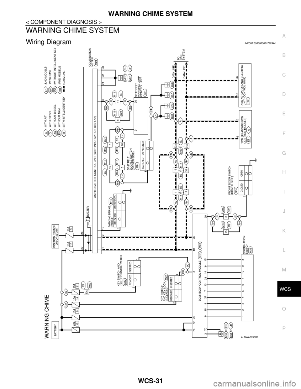
WARNING CHIME SYSTEM
Wiring DiagramINFOID:0000000001722944
ALNWA0136GB
Page 5755 of 5883

WCS-40
< ECU DIAGNOSIS >
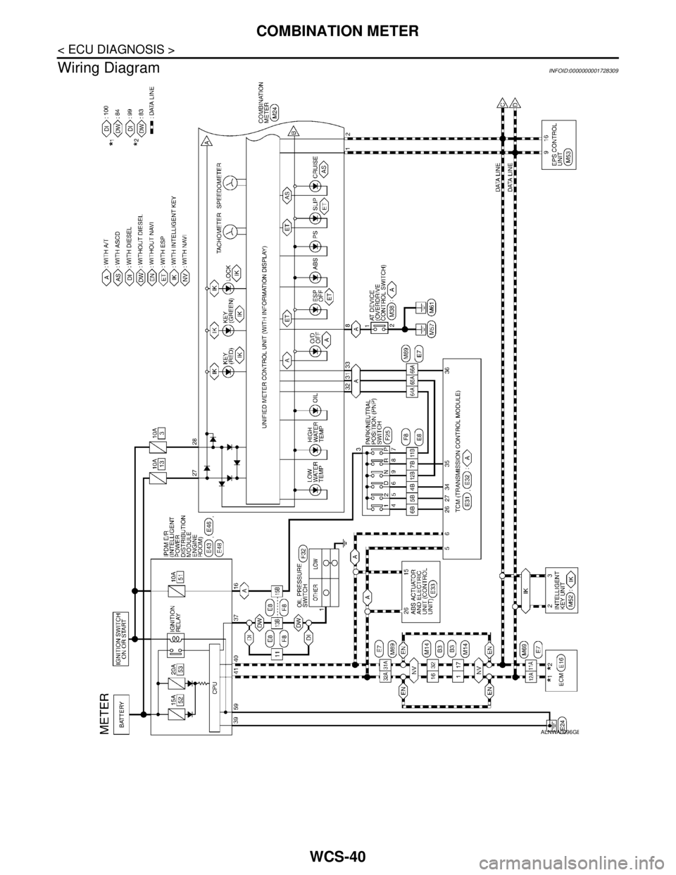
COMBINATION METER
Wiring Diagram
INFOID:0000000001728309
ALNWA0096GB
Page 5786 of 5883

WCS
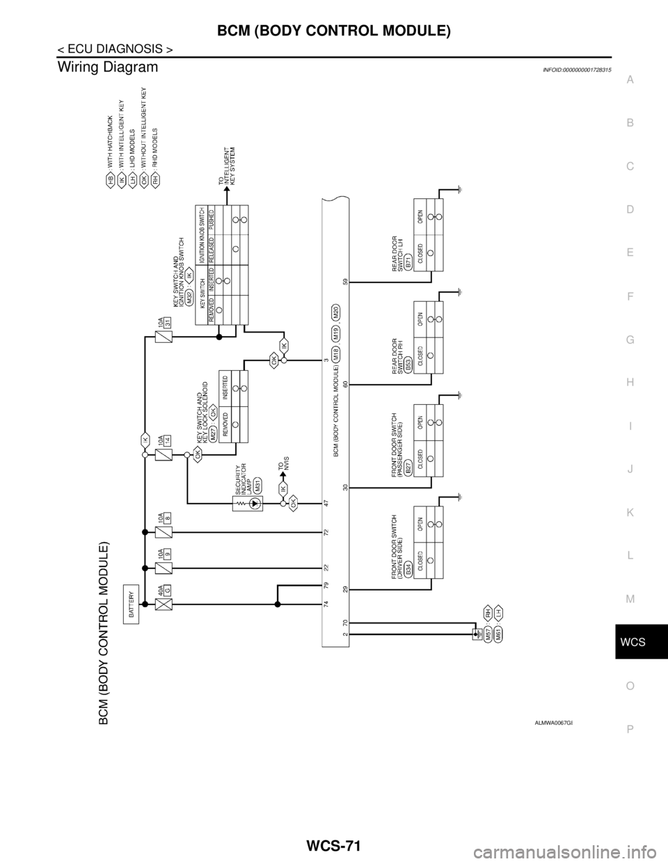
BCM (BODY CONTROL MODULE)
WCS-71
< ECU DIAGNOSIS >
C
D
E
F
G
H
I
J
K
L
MB A
O
P
Wiring DiagramINFOID:0000000001728315
ALMWA0067GB