2007 NISSAN TIIDA fuses
[x] Cancel search: fusesPage 3611 of 5883
![NISSAN TIIDA 2007 Service Repair Manual HAC-278
< COMPONENT DIAGNOSIS >[AUTO AIR CONDITIONER (W/NAVI)]
POWER SUPPLY AND GROUND CIRCUIT FOR CONTROLLER
A/C Auto Amp Power and Ground Diagnosis Procedure
INFOID:0000000001547370
DIAGNOSTIC PROCE NISSAN TIIDA 2007 Service Repair Manual HAC-278
< COMPONENT DIAGNOSIS >[AUTO AIR CONDITIONER (W/NAVI)]
POWER SUPPLY AND GROUND CIRCUIT FOR CONTROLLER
A/C Auto Amp Power and Ground Diagnosis Procedure
INFOID:0000000001547370
DIAGNOSTIC PROCE](/manual-img/5/57395/w960_57395-3610.png)
HAC-278
< COMPONENT DIAGNOSIS >[AUTO AIR CONDITIONER (W/NAVI)]
POWER SUPPLY AND GROUND CIRCUIT FOR CONTROLLER
A/C Auto Amp Power and Ground Diagnosis Procedure
INFOID:0000000001547370
DIAGNOSTIC PROCEDURE FOR A/C SYSTEM
SYMPTOM: A/C system does not come on.
1.CHECK POWER SUPPLY CIRCUIT FOR FRONT AIR CONTROL.
1. Turn ignition switch OFF.
2. Disconnect front air control connector.
3. Check voltage between front air control harness connector and
ground.
OK or NG
OK >> GO TO 2.
NG >> Check 10A fuses Nos. 2, 13 and 16, located in the fuse block (J/B).
If fuses are OK, check harness for open circuit. Repair or replace if necessary.
If fuses are NG, replace fuse and check harness for short circuit. Repair or replace if necessary.
2.CHECK GROUND CIRCUIT FOR FRONT AIR CONTROL
1. Turn ignition switch OFF.
2. Check continuity between front air control harness connector
and ground.
OK or NG
OK >> Replace front air control Refer to XX.
NG >> Repair or replace harness.
SJIA0877E
Terminals Ignition switch position
(+) (-)
OFF ACC ON
Connector Terminal
Ground
front air control:
M8519Battery
voltageBattery
voltageBattery
voltage
11Approx.
0VApprox.
0VBattery
voltage
18Approx.
0VApprox.
0VBattery
voltage
SJIA0878E
Connector Terminal
GroundContinuity
front air control:
M8520 Yes
SJIA0879E
Page 4333 of 5883

MWI-26
< COMPONENT DIAGNOSIS >
POWER SUPPLY AND GROUND CIRCUIT
POWER SUPPLY AND GROUND CIRCUIT
COMBINATION METER
COMBINATION METER : Diagnosis ProcedureINFOID:0000000001374688
1.CHECK FUSES
Check for blown combination meter fuses.
Is the inspection result normal?
YES >> GO TO 2
NO >> If fuse is blown, be sure to eliminate cause of malfunction before installing new fuse.
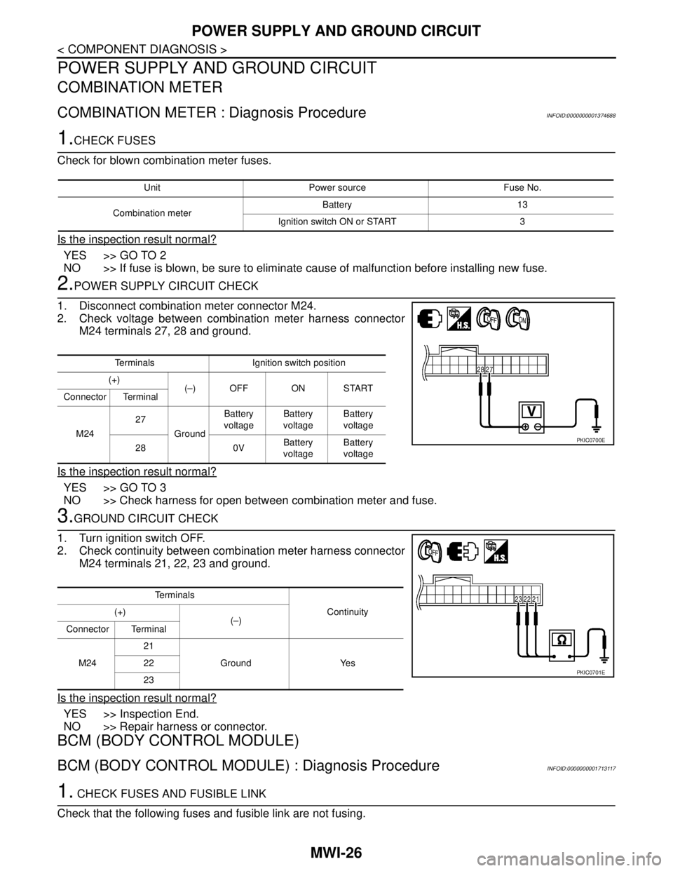
2.POWER SUPPLY CIRCUIT CHECK
1. Disconnect combination meter connector M24.
2. Check voltage between combination meter harness connector
M24 terminals 27, 28 and ground.
Is the inspection result normal?
YES >> GO TO 3
NO >> Check harness for open between combination meter and fuse.
3.GROUND CIRCUIT CHECK
1. Turn ignition switch OFF.
2. Check continuity between combination meter harness connector
M24 terminals 21, 22, 23 and ground.
Is the inspection result normal?
YES >> Inspection End.
NO >> Repair harness or connector.
BCM (BODY CONTROL MODULE)
BCM (BODY CONTROL MODULE) : Diagnosis ProcedureINFOID:0000000001713117
1. CHECK FUSES AND FUSIBLE LINK
Check that the following fuses and fusible link are not fusing.
Unit Power source Fuse No.
Combination meterBattery 13
Ignition switch ON or START 3
Terminals Ignition switch position
(+)
(–) OFF ON START
Connector Terminal
M2427
GroundBattery
voltageBattery
voltageBattery
voltage
28 0VBattery
voltageBattery
voltage
PKIC0700E
Te r m i n a l s
Continuity (+)
(–)
Connector Terminal
M2421
Ground Yes 22
23
PKIC0701E
Page 4334 of 5883

MWI
POWER SUPPLY AND GROUND CIRCUIT
MWI-27
< COMPONENT DIAGNOSIS >
C
D
E
F
G
H
I
J
K
L
MB A
O
P
Is the fuse fusing?
YES >> Replace the blown fuse or fusible link after repairing the affected circuit if a fuse or fusible link is
blown.
NO >> GO TO 2.
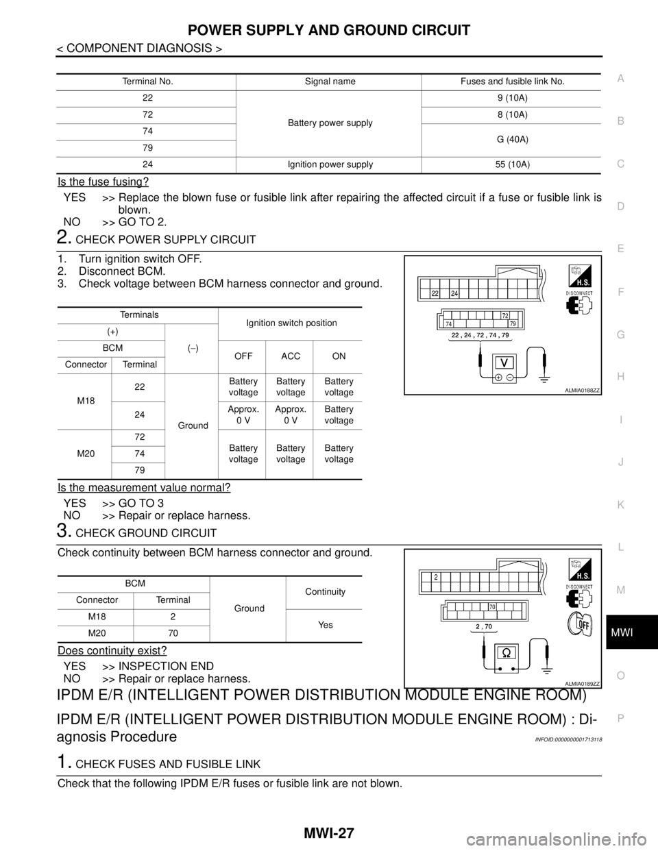
2. CHECK POWER SUPPLY CIRCUIT
1. Turn ignition switch OFF.
2. Disconnect BCM.
3. Check voltage between BCM harness connector and ground.
Is the measurement value normal?
YES >> GO TO 3
NO >> Repair or replace harness.
3. CHECK GROUND CIRCUIT
Check continuity between BCM harness connector and ground.
Does continuity exist?
YES >> INSPECTION END
NO >> Repair or replace harness.
IPDM E/R (INTELLIGENT POWER DISTRIBUTION MODULE ENGINE ROOM)
IPDM E/R (INTELLIGENT POWER DISTRIBUTION MODULE ENGINE ROOM) : Di-
agnosis Procedure
INFOID:0000000001713118
1. CHECK FUSES AND FUSIBLE LINK
Check that the following IPDM E/R fuses or fusible link are not blown.
Terminal No. Signal name Fuses and fusible link No.
22
Battery power supply9 (10A)
728 (10A)
74
G (40A)
79
24 Ignition power supply 55 (10A)
Te r m i n a l s
Ignition switch position
(+)
(−) BCM
OFF ACC ON
Connector Terminal
M1822
GroundBattery
voltageBattery
voltageBattery
voltage
24Approx.
0 VApprox.
0 VBattery
voltage
M2072
Battery
voltageBattery
voltageBattery
voltage 74
79
ALMIA0188ZZ
BCM
GroundContinuity
Connector Terminal
M18 2
Ye s
M20 70
ALMIA0189ZZ
Page 4430 of 5883
![NISSAN TIIDA 2007 Service Repair Manual PCS-16
< COMPONENT DIAGNOSIS >[IPDM E/R]
POWER SUPPLY AND GROUND CIRCUIT
POWER SUPPLY AND GROUND CIRCUIT
Diagnosis ProcedureINFOID:0000000001697594
1. CHECK FUSES AND FUSIBLE LINK
Check that the follo NISSAN TIIDA 2007 Service Repair Manual PCS-16
< COMPONENT DIAGNOSIS >[IPDM E/R]
POWER SUPPLY AND GROUND CIRCUIT
POWER SUPPLY AND GROUND CIRCUIT
Diagnosis ProcedureINFOID:0000000001697594
1. CHECK FUSES AND FUSIBLE LINK
Check that the follo](/manual-img/5/57395/w960_57395-4429.png)
PCS-16
< COMPONENT DIAGNOSIS >[IPDM E/R]
POWER SUPPLY AND GROUND CIRCUIT
POWER SUPPLY AND GROUND CIRCUIT
Diagnosis ProcedureINFOID:0000000001697594
1. CHECK FUSES AND FUSIBLE LINK
Check that the following IPDM E/R fuses or fusible link are not blown.
Is the fuse blown?
YES >> Replace the blown fuse or fusible link after repairing the affected circuit.
NO >> GO TO 2
2. CHECK BATTERY POWER SUPPLY CIRCUIT
1. Turn ignition switch OFF.
2. Disconnect IPDM E/R.
3. Check voltage between IPDM E/R harness connectors and
ground.
Is the measurement value normal?
YES >> GO TO 3
NO >> Repair or replace harness.
3. CHECK GROUND CIRCUIT
1. Turn ignition switch OFF.
2. Check continuity between IPDM E/R harness connectors and
ground.
Does continuity exist?
YES >> Inspection End.
NO >> Repair or replace harness.
Terminal No. Signal name Fusible link No.
1 Battery A, D
2 Battery C
12 Ignition switch ON or START H
Terminals Ignition switch position
(+)
(−) OFF ON START
Connector Terminal
E42 (A)1
GroundBattery
voltageBattery
voltageBattery
voltage
2Battery
voltageBattery
voltageBattery
voltage
E43 (B) 12 0VBattery
voltageBattery
voltage
AWMIA0023ZZ
IPDM E/R
GroundContinuity
Connector Terminal
E46 (A) 38
Ye s
E48 (B) 59
AWMIA0024ZZ
Page 4662 of 5883
![NISSAN TIIDA 2007 Service Repair Manual POWER SUPPLY AND GROUND CIRCUIT
SEC-37
< COMPONENT DIAGNOSIS >[WITH INTELLIGENT KEY SYSTEM]
C
D
E
F
G
H
I
J
L
MA
B
SEC
N
O
P
POWER SUPPLY AND GROUND CIRCUIT
INTELLIGENT KEY UNIT
INTELLIGENT KEY UNIT : NISSAN TIIDA 2007 Service Repair Manual POWER SUPPLY AND GROUND CIRCUIT
SEC-37
< COMPONENT DIAGNOSIS >[WITH INTELLIGENT KEY SYSTEM]
C
D
E
F
G
H
I
J
L
MA
B
SEC
N
O
P
POWER SUPPLY AND GROUND CIRCUIT
INTELLIGENT KEY UNIT
INTELLIGENT KEY UNIT :](/manual-img/5/57395/w960_57395-4661.png)
POWER SUPPLY AND GROUND CIRCUIT
SEC-37
< COMPONENT DIAGNOSIS >[WITH INTELLIGENT KEY SYSTEM]
C
D
E
F
G
H
I
J
L
MA
B
SEC
N
O
P
POWER SUPPLY AND GROUND CIRCUIT
INTELLIGENT KEY UNIT
INTELLIGENT KEY UNIT : Diagnosis ProcedureINFOID:0000000001532053
1.CHECK FUSES
Check that the following fuses are not blown.
Are the fuses blown?
YES >> Replace the blown fuse after repairing the affected circuit if a fuse is blown.
NO >> GO TO 2.
2.CHECK POWER SUPPLY CIRCUIT
1. Turn ignition switch OFF.
2. Disconnect Intelligent Key unit connector.
3. Check voltage between Intelligent Key unit harness connector
M52 terminals 6, 10, 11 and ground.
Is the inspection result normal?
YES >> GO TO 3.
NO >> Repair harness or connector.
3.CHECK GROUND CIRCUIT
Terminal No. Signal name Fuse No.
11 Battery power supply 31 (10A)
10 Ignition power supply (ACC/ON) 6 (10A)
6 Ignition power supply (ON/START) 2 (10A)
ALKIA0736ZZ
Te r m i n a lIgnition switch position
(+) (−)
OFF ACC ON Intelligent Key unit
Ground Connector Terminal
M5211 Battery voltage Battery voltage Battery voltage
10 0V Battery voltage Battery voltage
6 0V Battery voltage Battery voltage
Page 4725 of 5883
![NISSAN TIIDA 2007 Service Repair Manual SEC-100
< COMPONENT DIAGNOSIS >[WITHOUT INTELLIGENT KEY SYSTEM]
POWER SUPPLY AND GROUND CIRCUIT
POWER SUPPLY AND GROUND CIRCUIT
BCM
BCM : Diagnosis ProcedureINFOID:0000000001404197
1.CHECK FUSES AND F NISSAN TIIDA 2007 Service Repair Manual SEC-100
< COMPONENT DIAGNOSIS >[WITHOUT INTELLIGENT KEY SYSTEM]
POWER SUPPLY AND GROUND CIRCUIT
POWER SUPPLY AND GROUND CIRCUIT
BCM
BCM : Diagnosis ProcedureINFOID:0000000001404197
1.CHECK FUSES AND F](/manual-img/5/57395/w960_57395-4724.png)
SEC-100
< COMPONENT DIAGNOSIS >[WITHOUT INTELLIGENT KEY SYSTEM]
POWER SUPPLY AND GROUND CIRCUIT
POWER SUPPLY AND GROUND CIRCUIT
BCM
BCM : Diagnosis ProcedureINFOID:0000000001404197
1.CHECK FUSES AND FUSIBLE LINK
Check that the following fuses and fusible link are not blown.
Are the fuses or fusible link blown?
YES >> Replace the blown fuse or fusible link after repairing the affected circuit if a fuse or fusible link is
blown.
NO >> GO TO 2.
2.CHECK POWER SUPPLY CIRCUIT
1. Turn ignition switch OFF.
2. Disconnect BCM connectors.
3. Check voltage between BCM harness connector and ground.
Is the measurement value normal?
YES >> GO TO 3.
NO >> Repair harness or connector.
3.CHECK GROUND CIRCUIT
Check continuity between BCM harness connector and ground.
Does continuity exist?
YES >> INSPECTION END
NO >> Repair harness or connector.
Terminal No. Signal name Fuses and fusible link No.
22
Battery power supply9 (10A)
74, 79G (40A)
24 Ignition power supply 55 (10A)
Te r m i n a l s
Ignition switch position
(+)
(−) BCM
OFF ACC ON
Connector Terminal
M1824
GroundApprox. 0 V Approx. 0 V Battery voltage
22
Battery voltage Battery voltage Battery voltage
M20 74, 79
BCM
GroundContinuity
Connector Terminal
M18 2
Ye s
M20 70
Page 4780 of 5883

ON BOARD DIAGNOSTIC (OBD) SYSTEM
SRC-11
< FUNCTION DIAGNOSIS >
C
D
E
F
G
I
J
K
L
MA
B
SRC
N
O
P
ON BOARD DIAGNOSTIC (OBD) SYSTEM
Trouble Diagnosis IntroductionINFOID:0000000001396360
CAUTION:
Do not use electrical test equipment on any circuit related to the SRS unless instructed to do so in
this Service Manual. SRS wiring harnesses can be identified by yellow and/or orange harness con-
nectors.
Do not attempt to repair, splice or modify SRS wiring harnesses. If a harness is damaged, replace it
with a new one.
Keep ground connections clean.
DIAGNOSIS FUNCTION
The SRS self-diagnosis results can be read by using “AIR BAG” warning lamp and/or CONSULT-III.
The User mode is exclusively prepared for the customer (driver). This mode warns the driver of a system mal-
function through the operation of the “AIR BAG” warning lamp.
The Diagnosis mode allows the technician to locate and inspect the malfunctioning part.
The mode applications for the “AIR BAG” warning lamp and CONSULT-III are as follows:
HOW TO PERFORM TROUBLE DIAGNOSES FOR QUICK AND ACCURATE REPAIR
A good understanding of the malfunction conditions can make troubleshooting faster and more accurate.
In general, each customer feels differently about a malfunction. It is important to fully understand the symp-
toms or conditions for a customer complaint.
Information From Customer
WHAT - Vehicle model
WHEN - Date, Frequencies
WHERE - Road conditions
HOW - Operating conditions, Symptoms
Preliminary Check
Check that the following parts are in good order.
Battery
Fuses
System component-to-harness connections
SRS Operation CheckINFOID:0000000001396361
DIAGNOSTIC PROCEDURE 1
Checking SRS Operation Using “AIR BAG” Warning Lamp—User Mode
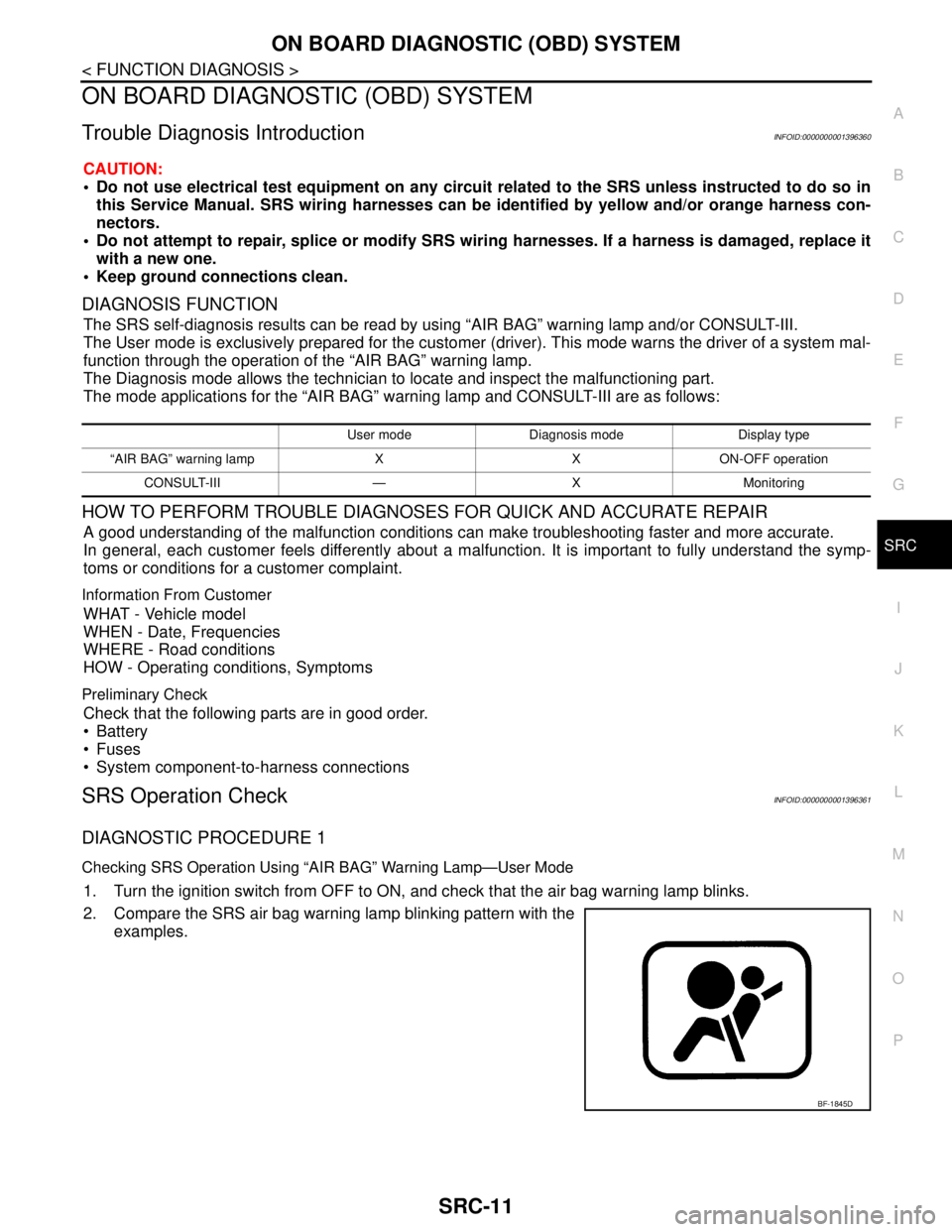
1. Turn the ignition switch from OFF to ON, and check that the air bag warning lamp blinks.
2. Compare the SRS air bag warning lamp blinking pattern with the
examples.
User mode Diagnosis mode Display type
“AIR BAG” warning lamp X X ON-OFF operation
CONSULT-III — X Monitoring
BF-1845D
Page 4824 of 5883

SEAT BELT WARNING LAMP CONTROL UNIT
SRC-55
< COMPONENT DIAGNOSIS >
C
D
E
F
G
I
J
K
L
MA
B
SRC
N
O
P
SEAT BELT WARNING LAMP CONTROL UNIT
Power Supply and Ground Circuit Check for Seat Belt Warning Lamp Control Unit
INFOID:0000000001724689
1.CHECK FUSES
Check for blown fuses.
Are any fuses blown?
YES >> Install new fuse. Eliminate cause of malfunction if fuse blows again.
NO >> GO TO 2
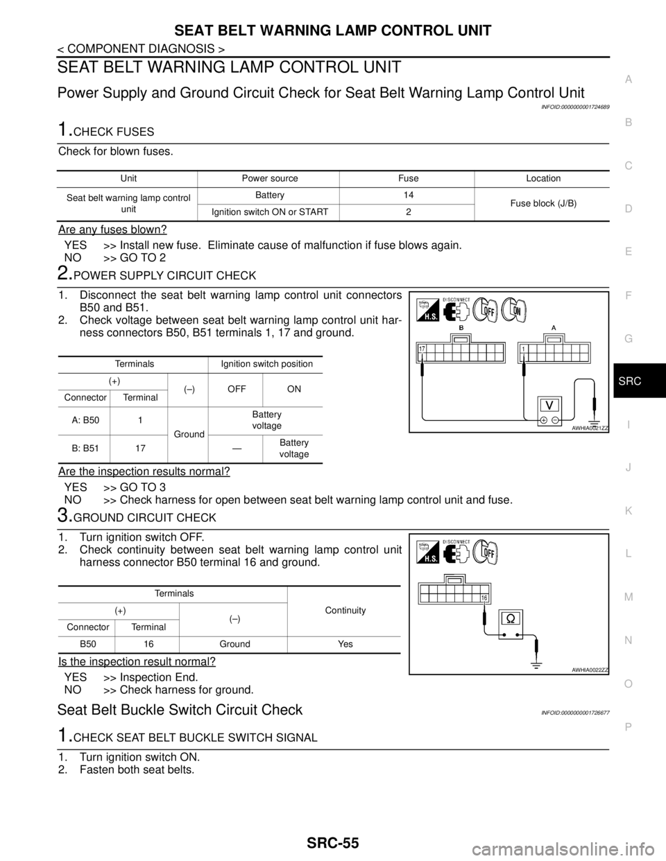
2.POWER SUPPLY CIRCUIT CHECK
1. Disconnect the seat belt warning lamp control unit connectors
B50 and B51.
2. Check voltage between seat belt warning lamp control unit har-
ness connectors B50, B51 terminals 1, 17 and ground.
Are the inspection results normal?
YES >> GO TO 3
NO >> Check harness for open between seat belt warning lamp control unit and fuse.
3.GROUND CIRCUIT CHECK
1. Turn ignition switch OFF.
2. Check continuity between seat belt warning lamp control unit
harness connector B50 terminal 16 and ground.
Is the inspection result normal?
YES >> Inspection End.
NO >> Check harness for ground.
Seat Belt Buckle Switch Circuit CheckINFOID:0000000001726677
1.CHECK SEAT BELT BUCKLE SWITCH SIGNAL
1. Turn ignition switch ON.
2. Fasten both seat belts.
Unit Power source Fuse Location
Seat belt warning lamp control
unitBattery 14
Fuse block (J/B)
Ignition switch ON or START 2
Terminals Ignition switch position
(+)
(–) OFF ON
Connector Terminal
A: B50 1
GroundBattery
voltage
B: B51 17 —Battery
voltage
AWHIA0021ZZ
Te r m i n a l s
Continuity (+)
(–)
Connector Terminal
B50 16 Ground Yes
AWHIA0022ZZ