Page 4851 of 5883

SRC-82
< SYMPTOM DIAGNOSIS >
SRS AIR BAG SYSTEM
SYMPTOM DIAGNOSIS
SRS AIR BAG SYSTEM
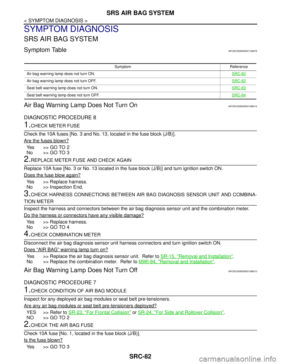
Symptom TableINFOID:0000000001726679
Air Bag Warning Lamp Does Not Turn OnINFOID:0000000001396414
DIAGNOSTIC PROCEDURE 8
1.CHECK METER FUSE
Check the 10A fuses [No. 3 and No. 13, located in the fuse block (J/B)].
Are the fuses blown?
Ye s > > G O T O 2
No >> GO TO 3
2.REPLACE METER FUSE AND CHECK AGAIN
Replace 10A fuse [No. 3 or No. 13 located in the fuse block (J/B)] and turn ignition switch ON.
Does the fuse blow again?
Yes >> Replace harness.
No >> Inspection End.
3.CHECK HARNESS CONNECTIONS BETWEEN AIR BAG DIAGNOSIS SENSOR UNIT AND COMBINA-
TION METER
Inspect the harness and connectors between the air bag diagnosis sensor unit and the combination meter.
Do the harness or connectors have any visible damage?
Yes >> Replace harness.
No >> GO TO 4
4.CHECK COMBINATION METER
Disconnect the air bag diagnosis sensor unit harness connectors and turn ignition switch ON.
Does
“AIR BAG” warning lamp turn on?
Yes >> Replace the air bag diagnosis sensor unit. Refer to SR-15, "Removal and Installation".
No >> Replace the combination meter. Refer to MWI-94, "
Removal and Installation".
Air Bag Warning Lamp Does Not Turn OffINFOID:0000000001396413
DIAGNOSTIC PROCEDURE 7
1.CHECK CONDITION OF AIR BAG MODULE
Inspect for any deployed air bag modules or seat belt pre-tensioners.
Are any air bag modules or seat belt pre-tensioners deployed?
YES >> Refer to SR-23, "For Frontal Collision" or SR-24, "For Side and Rollover Collision".
NO >> GO TO 2
2.CHECK THE AIR BAG FUSE
Check 10A fuse [No. 1, located in the fuse block (J/B)].
Is the fuse blown?
Ye s > > G O T O 3
Symptom Reference
Air bag warning lamp does not turn ON.SRC-82
Air bag warning lamp does not turn OFF.SRC-82
Seat belt warning lamp does not turn ON.SRC-83
Seat belt warning lamp does not turn OFF.SRC-84
Page 5736 of 5883

WCS
POWER SUPPLY AND GROUND CIRCUIT
WCS-21
< COMPONENT DIAGNOSIS >
C
D
E
F
G
H
I
J
K
L
MB A
O
P
COMPONENT DIAGNOSIS
POWER SUPPLY AND GROUND CIRCUIT
COMBINATION METER
COMBINATION METER : Diagnosis ProcedureINFOID:0000000001728304
1.CHECK FUSES
Check for blown combination meter fuses.
Is the inspection result normal?
YES >> GO TO 2
NO >> If fuse is blown, be sure to eliminate cause of malfunction before installing new fuse.
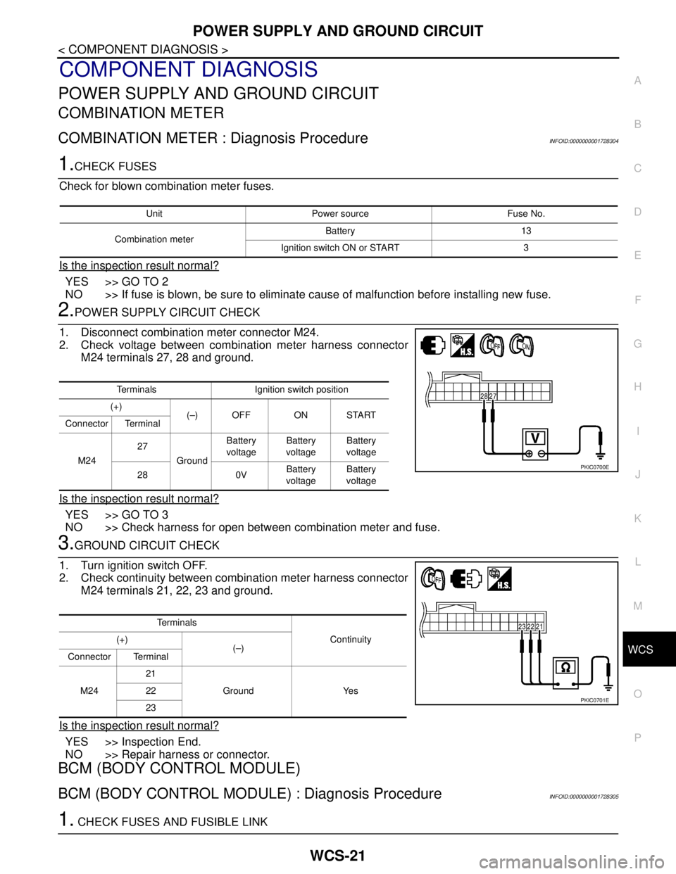
2.POWER SUPPLY CIRCUIT CHECK
1. Disconnect combination meter connector M24.
2. Check voltage between combination meter harness connector
M24 terminals 27, 28 and ground.
Is the inspection result normal?
YES >> GO TO 3
NO >> Check harness for open between combination meter and fuse.
3.GROUND CIRCUIT CHECK
1. Turn ignition switch OFF.
2. Check continuity between combination meter harness connector
M24 terminals 21, 22, 23 and ground.
Is the inspection result normal?
YES >> Inspection End.
NO >> Repair harness or connector.
BCM (BODY CONTROL MODULE)
BCM (BODY CONTROL MODULE) : Diagnosis ProcedureINFOID:0000000001728305
1. CHECK FUSES AND FUSIBLE LINK
Unit Power source Fuse No.
Combination meterBattery 13
Ignition switch ON or START 3
Terminals Ignition switch position
(+)
(–) OFF ON START
Connector Terminal
M2427
GroundBattery
voltageBattery
voltageBattery
voltage
28 0VBattery
voltageBattery
voltage
PKIC0700E
Te r m i n a l s
Continuity (+)
(–)
Connector Terminal
M2421
Ground Yes 22
23
PKIC0701E
Page 5737 of 5883

WCS-22
< COMPONENT DIAGNOSIS >
POWER SUPPLY AND GROUND CIRCUIT
Check that the following fuses and fusible link are not fusing.
Is the fuse fusing?
YES >> Replace the blown fuse or fusible link after repairing the affected circuit if a fuse or fusible link is
blown.
NO >> GO TO 2.
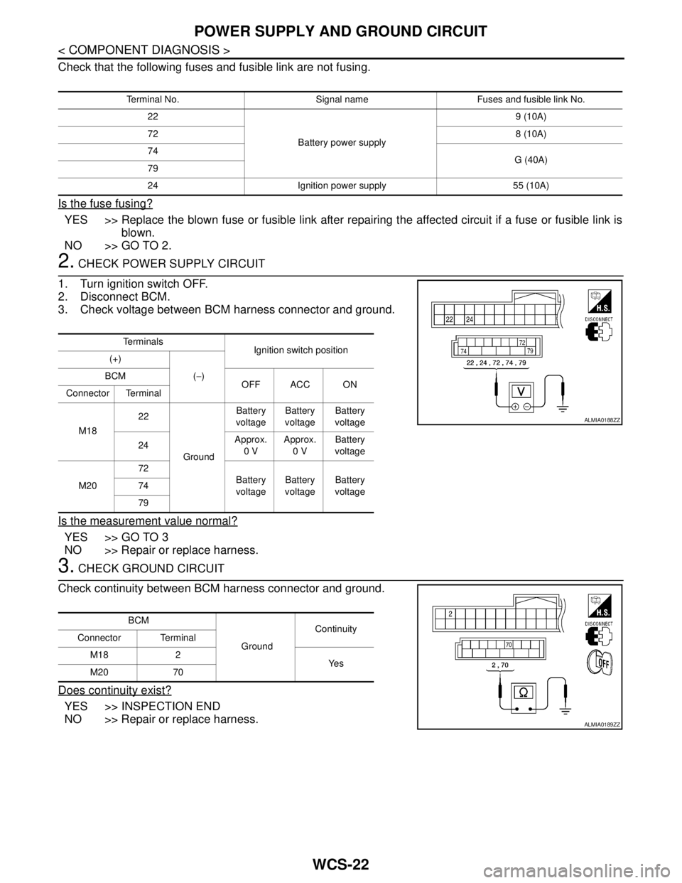
2. CHECK POWER SUPPLY CIRCUIT
1. Turn ignition switch OFF.
2. Disconnect BCM.
3. Check voltage between BCM harness connector and ground.
Is the measurement value normal?
YES >> GO TO 3
NO >> Repair or replace harness.
3. CHECK GROUND CIRCUIT
Check continuity between BCM harness connector and ground.
Does continuity exist?
YES >> INSPECTION END
NO >> Repair or replace harness.
Terminal No. Signal name Fuses and fusible link No.
22
Battery power supply9 (10A)
728 (10A)
74
G (40A)
79
24 Ignition power supply 55 (10A)
Te r m i n a l s
Ignition switch position
(+)
(−) BCM
OFF ACC ON
Connector Terminal
M1822
GroundBattery
voltageBattery
voltageBattery
voltage
24Approx.
0 VApprox.
0 VBattery
voltage
M2072
Battery
voltageBattery
voltageBattery
voltage 74
79
ALMIA0188ZZ
BCM
GroundContinuity
Connector Terminal
M18 2
Ye s
M20 70
ALMIA0189ZZ
Page 5819 of 5883
WIPER AND WASHER FUSE, FUSIBLE LINK
WW-17
< COMPONENT DIAGNOSIS >
C
D
E
F
G
H
I
J
K
MA
B
WW
N
O
P
COMPONENT DIAGNOSIS
WIPER AND WASHER FUSE, FUSIBLE LINK
DescriptionINFOID:0000000001366608
Fuse, fusible link list
Diagnosis ProcedureINFOID:0000000001366609
1. CHECK FUSES AND FUSIBLE LINK
Check that the following fuses and fusible link are not blown.
Is the fuse or fusible link blown?
YES >> Replace the fuse or fusible link after repairing the applicable circuit.
NO >> The fuse or fusible link is normal.
Unit Location Fuse No. Capacity
Front wiper motor IPDM E/R 39 30 A
Front and rear washer motor Fuse block (J/B) 4 15 A
Headlamp washer motor Fuse and fusible link box L 30 A
Unit Location Fuse No. Capacity
Front wiper motor IPDM E/R 39 30 A
Front and rear washer motor Fuse block (J/B) 4 15 A
Headlamp washer motor Fuse and fusible link box L 30 A