2007 NISSAN TIIDA ABS
[x] Cancel search: ABSPage 3122 of 5883
EXT-18
< ON-VEHICLE REPAIR >
REAR BUMPER
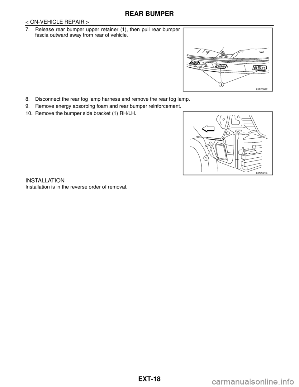
7. Release rear bumper upper retainer (1), then pull rear bumper
fascia outward away from rear of vehicle.
8. Disconnect the rear fog lamp harness and remove the rear fog lamp.
9. Remove energy absorbing foam and rear bumper reinforcement.
10. Remove the bumper side bracket (1) RH/LH.
INSTALLATION
Installation is in the reverse order of removal.
LIIA2580E
LIIA2921E
Page 3166 of 5883
FL-6
< ON-VEHICLE REPAIR >
FUEL LEVEL SENSOR UNIT, FUEL FILTER AND FUEL PUMP ASSEMBLY
b. Disconnect fuel filler hose from fuel filler tube. Refer to FL-10, "HR16DE, HR18DE".
c. Insert fuel tubing into fuel tank through fuel filler hose to drain fuel from fuel tank.
2. Release the fuel pressure from the fuel lines. Refer to EC-377, "
Inspection" (HR16DE with EURO-OBD),
EC-681, "
Inspection" (HR16DE without EURO-OBD), EC-1035, "Inspection" (MR18DE).
3. Open fuel filler lid.
4. Open fuel door and unscrew the fuel filler cap to release the pressure inside the fuel tank.
5. Remove rear seat bottom. Refer to SE-18, "
Removal and Installation".
6. Turn the four retainers 90° in a clockwise direction and remove the fuel pump inspection hole cover.
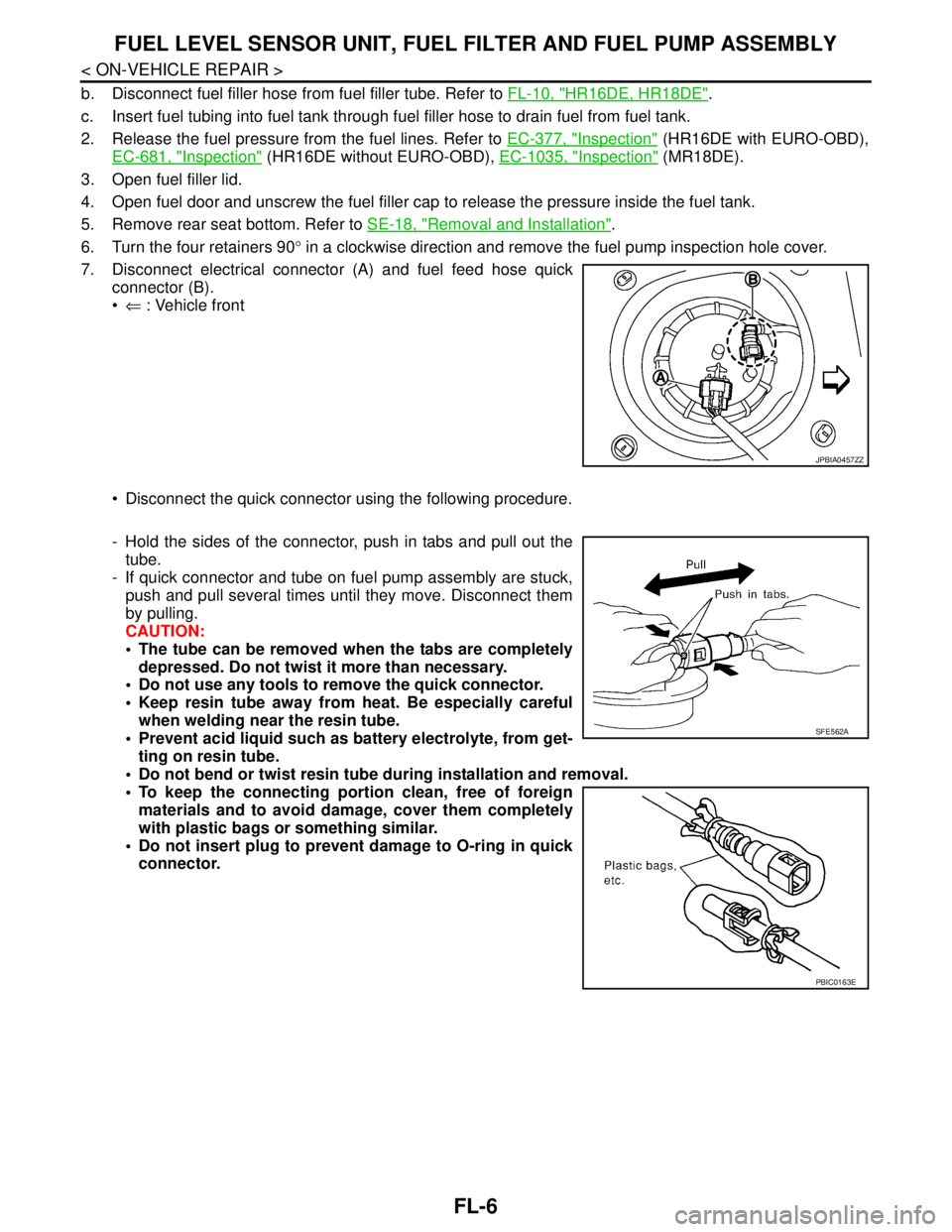
7. Disconnect electrical connector (A) and fuel feed hose quick
connector (B).
⇐ : Vehicle front
Disconnect the quick connector using the following procedure.
- Hold the sides of the connector, push in tabs and pull out the
tube.
- If quick connector and tube on fuel pump assembly are stuck,
push and pull several times until they move. Disconnect them
by pulling.
CAUTION:
The tube can be removed when the tabs are completely
depressed. Do not twist it more than necessary.
Do not use any tools to remove the quick connector.
Keep resin tube away from heat. Be especially careful
when welding near the resin tube.
Prevent acid liquid such as battery electrolyte, from get-
ting on resin tube.
Do not bend or twist resin tube during installation and removal.
To keep the connecting portion clean, free of foreign
materials and to avoid damage, cover them completely
with plastic bags or something similar.
Do not insert plug to prevent damage to O-ring in quick
connector.
JPBIA0457ZZ
SFE562A
PBIC0163E
Page 3167 of 5883
FUEL LEVEL SENSOR UNIT, FUEL FILTER AND FUEL PUMP ASSEMBLY
FL-7
< ON-VEHICLE REPAIR >
C
D
E
F
G
H
I
J
K
L
MA
FL
N
P O
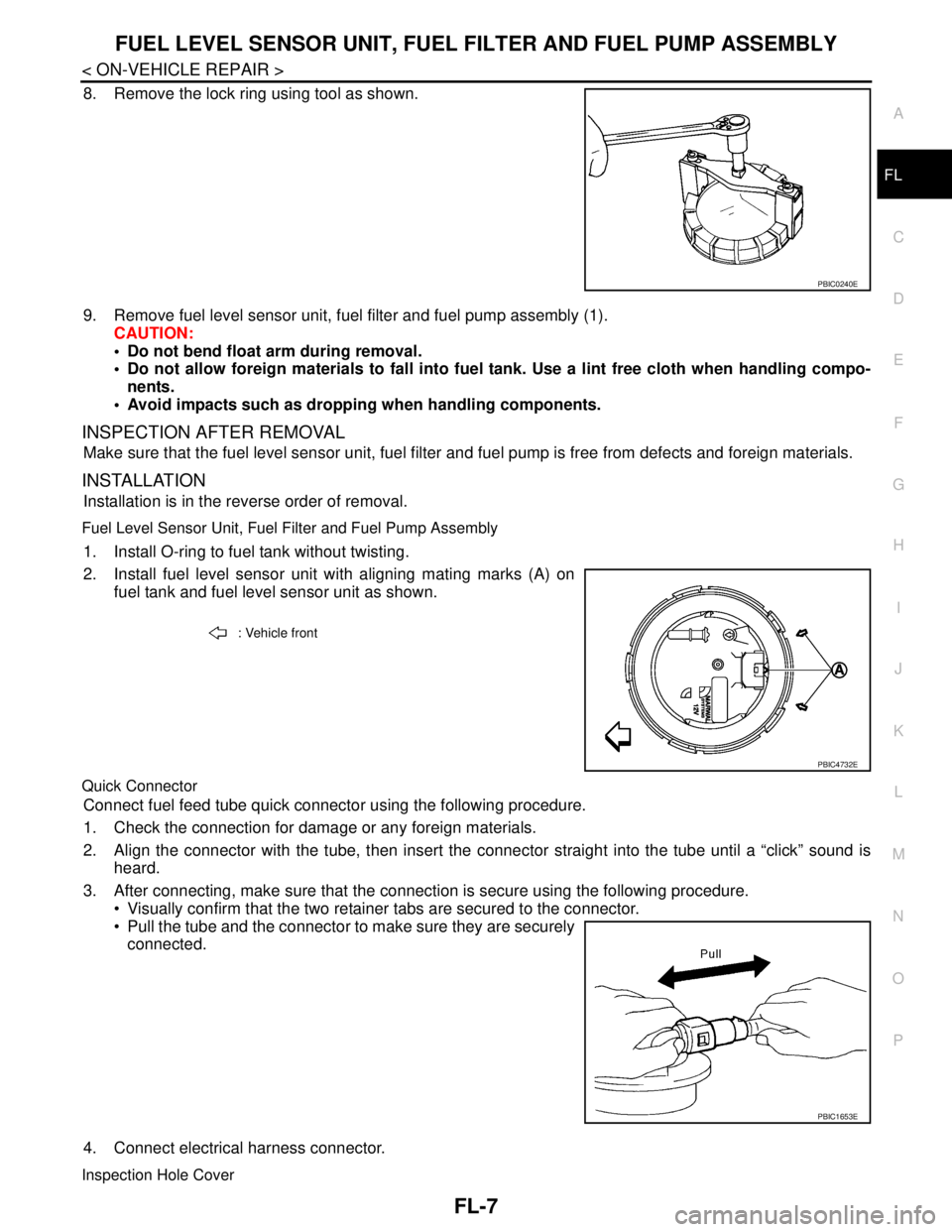
8. Remove the lock ring using tool as shown.
9. Remove fuel level sensor unit, fuel filter and fuel pump assembly (1).
CAUTION:
Do not bend float arm during removal.
Do not allow foreign materials to fall into fuel tank. Use a lint free cloth when handling compo-
nents.
Avoid impacts such as dropping when handling components.
INSPECTION AFTER REMOVAL
Make sure that the fuel level sensor unit, fuel filter and fuel pump is free from defects and foreign materials.
INSTALLATION
Installation is in the reverse order of removal.
Fuel Level Sensor Unit, Fuel Filter and Fuel Pump Assembly
1. Install O-ring to fuel tank without twisting.
2. Install fuel level sensor unit with aligning mating marks (A) on
fuel tank and fuel level sensor unit as shown.
Quick Connector
Connect fuel feed tube quick connector using the following procedure.
1. Check the connection for damage or any foreign materials.
2. Align the connector with the tube, then insert the connector straight into the tube until a “click” sound is
heard.
3. After connecting, make sure that the connection is secure using the following procedure.
Visually confirm that the two retainer tabs are secured to the connector.
Pull the tube and the connector to make sure they are securely
connected.
4. Connect electrical harness connector.
Inspection Hole Cover
PBIC0240E
: Vehicle front
PBIC4732E
PBIC1653E
Page 3169 of 5883
FUEL LEVEL SENSOR UNIT, FUEL FILTER AND FUEL PUMP ASSEMBLY
FL-9
< ON-VEHICLE REPAIR >
C
D
E
F
G
H
I
J
K
L
MA
FL
N
P O
1. Disconnect battery ground cable.
2. Open fuel filler lid and filler cap to release the pressure inside the fuel tank.
3. Remove rear seat cushion. Refer to SE-18, "
Removal and Installation".
4. Remove the fuel pump inspection hole cover.
5. Disconnect electrical connector.
6. Disconnect the quick connector.
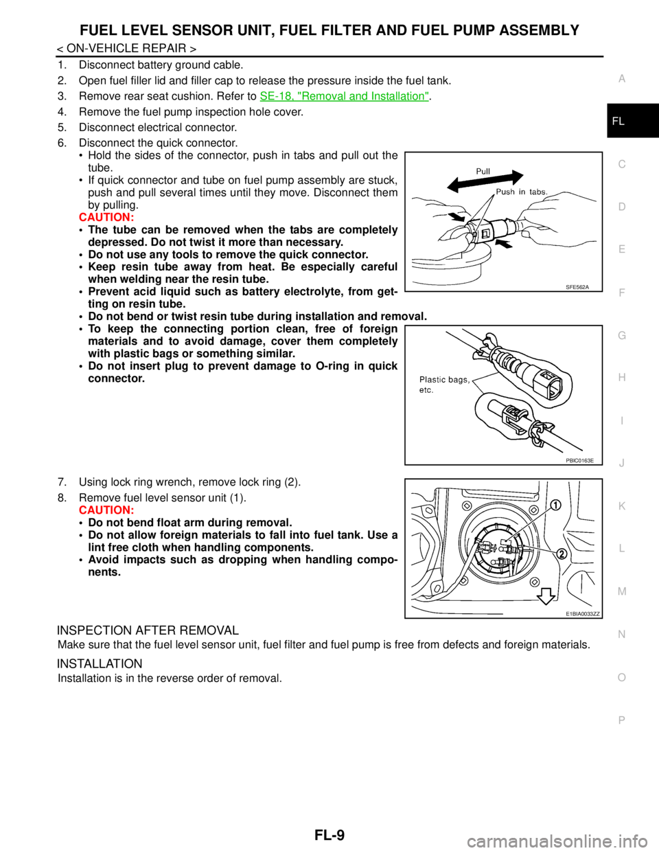
Hold the sides of the connector, push in tabs and pull out the
tube.
If quick connector and tube on fuel pump assembly are stuck,
push and pull several times until they move. Disconnect them
by pulling.
CAUTION:
The tube can be removed when the tabs are completely
depressed. Do not twist it more than necessary.
Do not use any tools to remove the quick connector.
Keep resin tube away from heat. Be especially careful
when welding near the resin tube.
Prevent acid liquid such as battery electrolyte, from get-
ting on resin tube.
Do not bend or twist resin tube during installation and removal.
To keep the connecting portion clean, free of foreign
materials and to avoid damage, cover them completely
with plastic bags or something similar.
Do not insert plug to prevent damage to O-ring in quick
connector.
7. Using lock ring wrench, remove lock ring (2).
8. Remove fuel level sensor unit (1).
CAUTION:
Do not bend float arm during removal.
Do not allow foreign materials to fall into fuel tank. Use a
lint free cloth when handling components.
Avoid impacts such as dropping when handling compo-
nents.
INSPECTION AFTER REMOVAL
Make sure that the fuel level sensor unit, fuel filter and fuel pump is free from defects and foreign materials.
INSTALLATION
Installation is in the reverse order of removal.
SFE562A
PBIC0163E
E1BIA0033ZZ
Page 3174 of 5883
FL-14
< ON-VEHICLE REPAIR >
FUEL TANK
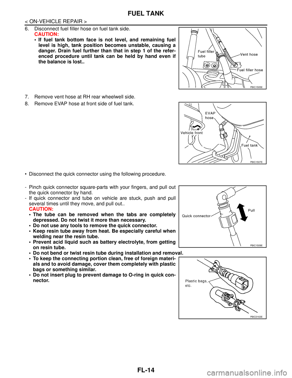
6. Disconnect fuel filler hose on fuel tank side.
CAUTION:
If fuel tank bottom face is not level, and remaining fuel
level is high, tank position becomes unstable, causing a
danger. Drain fuel further than that in step 1 of the refer-
enced procedure until tank can be held by hand even if
the balance is lost..
7. Remove vent hose at RH rear wheelwell side.
8. Remove EVAP hose at front side of fuel tank.
Disconnect the quick connector using the following procedure.
- Pinch quick connector square-parts with your fingers, and pull out
the quick connector by hand.
- If quick connector and tube on vehicle are stuck, push and pull
several times until they move, and pull out..
CAUTION:
The tube can be removed when the tabs are completely
depressed. Do not twist it more than necessary.
Do not use any tools to remove the quick connector.
Keep resin tube away from heat. Be especially careful when
welding near the resin tube.
Prevent acid liquid such as battery electrolyte, from getting
on resin tube.
Do not bend or twist resin tube during installation and removal.
To keep the connecting portion clean, free of foreign materi-
als and to avoid damage, cover them completely with plastic
bags or something similar.
Do not insert plug to prevent damage to O-ring in quick con-
nector.
PBIC1505E
PBIC1507E
PBIC1509E
PBIC0163E
Page 3182 of 5883
FSU-6
< ON-VEHICLE MAINTENANCE >
FRONT SUSPENSION ASSEMBLY
ON-VEHICLE MAINTENANCE
FRONT SUSPENSION ASSEMBLY
On-Vehicle Inspection and ServiceINFOID:0000000001716890
Make sure the mounting conditions (looseness, back lash) of each component and component conditions
(wear, damage) are normal.
INSPECTION OF LOWER BALL JOINT END PLAY
1. Set front wheels in a straight-ahead position. Do not depress brake pedal.
2. Place an iron bar or similar tool between transverse link and steering knuckle.
3. Measure axial end play by prying it up and down.
CAUTION:
Be careful not to damage ball joint boot. Do not damage the installation position by applying
excessive force.
STRUT INSPECTION
Check for oil leakage, damage and replace as necessary.
Wheel Alignment InspectionINFOID:0000000001716891
PRELIMINARY INSPECTION
WARNING:
Always adjust the alignment with the vehicle on a flat surface.
NOTE:
If alignment is out of specification, inspect and replace any damaged or worn rear suspension parts before
making any adjustments.
1. Check and adjust the wheel alignment with the vehicle under unladen conditions. “Unladen conditions”
means that the fuel, coolant, and lubricant are full; and that the spare tire, jack, hand tools and mats are in
their designated positions.
2. Check the tires for incorrect air pressure and excessive wear.
3. Check the wheels for run out and damage. Refer to WT-5, "
Inspection" .
4. Check the wheel bearing axial end play. Refer to FA X - 5 , "
On-Vehicle Inspection and Service" .
5. Check the shock absorbers for leaks or damage.
6. Check each mounting point of the suspension components for any excessive looseness or damage.
7. Check each link, arm, and the suspension member for any damage.
8. Check the vehicle height. Refer to FSU-18, "
Wheelarch Height (Unladen*)" .
GENERAL INFORMATION AND RECOMMENDATIONS
1. A Four-Wheel Thrust Alignment should be performed.
This type of alignment is recommended for any NISSAN vehicle.
The four-wheel “thrust” process helps ensure that the vehicle is properly aligned and the steering wheel
is centered.
The alignment machine itself should be capable of accepting any NISSAN vehicle.
The alignment machine should be checked to ensure that it is level.
2. Make sure the alignment machine is properly calibrated.
Your alignment machine should be regularly calibrated in order to give correct information.
Check with the manufacturer of your specific alignment machine for their recommended Service/Cali-
bration Schedule.
THE ALIGNMENT PROCESS
IMPORTANT: Use only the alignment specifications listed in this Service Manual. Refer to FSU-17, "Wheel
Alignment (Unladen*)" .
1. When displaying the alignment settings, many alignment machines use “indicators”: (Green/red, plus or
minus, Go/No Go). Do NOT use these indicators. Axial end play : 0 mm (0 in)
Page 3223 of 5883
TERMINOLOGY
GI-29
< HOW TO USE THIS MANUAL >
C
D
E
F
G
H
I
J
K
L
MB
GI
N
O
P
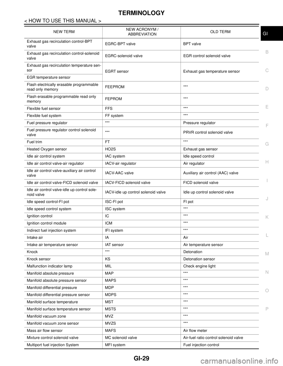
Exhaust gas recirculation control-BPT
valveEGRC-BPT valve BPT valve
Exhaust gas recirculation control-solenoid
valveEGRC-solenoid valve EGR control solenoid valve
Exhaust gas recirculation temperature sen-
sor
EGRT sensor Exhaust gas temperature sensor
EGR temperature sensor
Flash electrically erasable programmable
read only memoryFEEPROM ***
Flash erasable programmable read only
memoryFEPROM ***
Flexible fuel sensor FFS ***
Flexible fuel system FF system ***
Fuel pressure regulator *** Pressure regulator
Fuel pressure regulator control solenoid
valve*** PRVR control solenoid valve
Fuel trim FT ***
Heated Oxygen sensor HO2S Exhaust gas sensor
Idle air control system IAC system Idle speed control
Idle air control valve-air regulator IACV-air regulator Air regulator
Idle air control valve-auxiliary air control
valveIACV-AAC valve Auxiliary air control (AAC) valve
Idle air control valve-FICD solenoid valve IACV-FICD solenoid valve FICD solenoid valve
Idle air control valve-idle up control sole-
noid valveIACV-idle up control solenoid valve Idle up control solenoid valve
Idle speed control-FI pot ISC-FI pot FI pot
Idle speed control system ISC system ***
Ignition control IC ***
Ignition control module ICM ***
Indirect fuel injection system IFI system ***
Intake air IA Air
Intake air temperature sensor IAT sensor Air temperature sensor
Knock *** Detonation
Knock sensor KS Detonation sensor
Malfunction indicator lamp MIL Check engine light
Manifold absolute pressure MAP ***
Manifold absolute pressure sensor MAPS ***
Manifold differential pressure MDP ***
Manifold differential pressure sensor MDPS ***
Manifold surface temperature MST ***
Manifold surface temperature sensor MSTS ***
Manifold vacuum zone MVZ ***
Manifold vacuum zone sensor MVZS ***
Mass air flow sensor MAFS Air flow meter
Mixture control solenoid valve MC solenoid valve Air-fuel ratio control solenoid valve
Multiport fuel injection System MFI system Fuel injection controlNEW TERMNEW ACRONYM /
ABBREVIATIONOLD TERM
Page 3257 of 5883
CONSULT-III CHECKING SYSTEM
GI-63
< BASIC INSPECTION >
C
D
E
F
G
H
I
J
K
L
MB
GI
N
O
PCONSULT-III CHECKING SYSTEM
DescriptionINFOID:0000000001691472
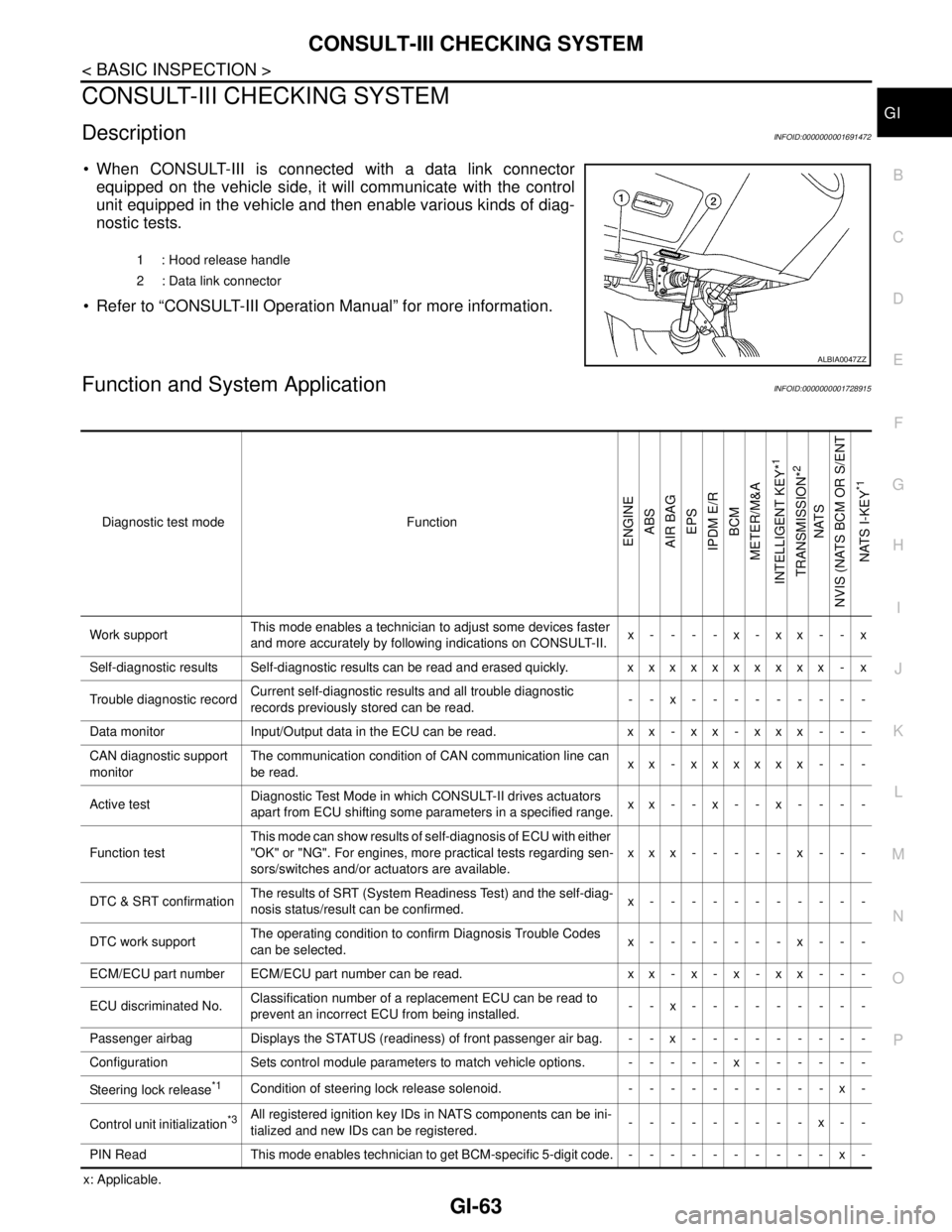
When CONSULT-III is connected with a data link connector
equipped on the vehicle side, it will communicate with the control
unit equipped in the vehicle and then enable various kinds of diag-
nostic tests.
Refer to “CONSULT-III Operation Manual” for more information.
Function and System ApplicationINFOID:0000000001728915
x: Applicable.1 : Hood release handle
2 : Data link connector
ALBIA0047ZZ
Diagnostic test mode Function
ENGINE
ABS
AIR BAG
EPS
IPDM E/R
BCM
METER/M&A
INTELLIGENT KEY*
1
TRANSMISSION*
2
NATS
NVIS (NATS BCM OR S/ENT
NATS I-KEY
*1
Work supportThis mode enables a technician to adjust some devices faster
and more accurately by following indications on CONSULT-II.x----x-xx--x
Self-diagnostic results Self-diagnostic results can be read and erased quickly. xxxxxxxxxx - x
Trouble diagnostic recordCurrent self-diagnostic results and all trouble diagnostic
records previously stored can be read.--x---------
Data monitor Input/Output data in the ECU can be read. x x - x x - x x x - - -
CAN diagnostic support
monitorThe communication condition of CAN communication line can
be read.xx - xxxxxx - - -
Active testDiagnostic Test Mode in which CONSULT-II drives actuators
apart from ECU shifting some parameters in a specified range.xx--x--x----
Function testThis mode can show results of self-diagnosis of ECU with either
"OK" or "NG". For engines, more practical tests regarding sen-
sors/switches and/or actuators are available.xxx-----x---
DTC & SRT confirmationThe results of SRT (System Readiness Test) and the self-diag-
nosis status/result can be confirmed.x-----------
DTC work supportThe operating condition to confirm Diagnosis Trouble Codes
can be selected.x-------x---
ECM/ECU part number ECM/ECU part number can be read. x x - x - x - x x - - -
ECU discriminated No.Classification number of a replacement ECU can be read to
prevent an incorrect ECU from being installed.--x---------
Passenger airbag Displays the STATUS (readiness) of front passenger air bag. --x---------
Configuration Sets control module parameters to match vehicle options. -----x------
Steering lock release
*1Condition of steering lock release solenoid. ----------x-
Control unit initialization
*3All registered ignition key IDs in NATS components can be ini-
tialized and new IDs can be registered.---------x--
PIN Read This mode enables technician to get BCM-specific 5-digit code.----------x-