2007 NISSAN TIIDA ECO mode
[x] Cancel search: ECO modePage 4739 of 5883
![NISSAN TIIDA 2007 Service Repair Manual SEC-114
< ECU DIAGNOSIS >[WITHOUT INTELLIGENT KEY SYSTEM]
IPDM E/R (INTELLIGENT POWER DISTRIBUTION MODULE ENGINE ROOM)
IPDM E/R (INTELLIGENT POWER DISTRIBUTION MODULE ENGINE
ROOM)
Reference ValueINFOI NISSAN TIIDA 2007 Service Repair Manual SEC-114
< ECU DIAGNOSIS >[WITHOUT INTELLIGENT KEY SYSTEM]
IPDM E/R (INTELLIGENT POWER DISTRIBUTION MODULE ENGINE ROOM)
IPDM E/R (INTELLIGENT POWER DISTRIBUTION MODULE ENGINE
ROOM)
Reference ValueINFOI](/manual-img/5/57395/w960_57395-4738.png)
SEC-114
< ECU DIAGNOSIS >[WITHOUT INTELLIGENT KEY SYSTEM]
IPDM E/R (INTELLIGENT POWER DISTRIBUTION MODULE ENGINE ROOM)
IPDM E/R (INTELLIGENT POWER DISTRIBUTION MODULE ENGINE
ROOM)
Reference ValueINFOID:0000000001404226
Refer to IPDM E/R.
Fail SafeINFOID:0000000001404229
CAN communication control
When CAN communication with ECM and BCM is impossible, IPDM E/R performs fail-safe control. After CAN
communication recovers normally, it also returns to normal control.
If no CAN communication is available with ECM
*1: HR engine models
*2: MR engine and K9K engine models
If no CAN communication is available with BCM
Ignition relay malfunction detection function
IPDM E/R monitors the voltage at the contact circuit and excitation coil circuit of the ignition relay inside it.
IPDM E/R judges the ignition relay error if the voltage differs between the contact circuit and the excitation
coil circuit.
If the ignition relay cannot turn OFF due to contact seizure, it activates the tail lamp relay for 10 minutes to
alert the user to the ignition relay malfunction when the ignition switch is turned OFF.
Control part Fail-safe in operation
Cooling fan The cooling fan relay-2*
1 or the cooling fan relay-3*2 turns ON when the ignition switch
is turned ON
Turns off the fan motor low relay when the ignition switch is turned OFF
A/C compressor A/C relay OFF
Control part Fail-safe in operation
Headlamp The headlamp low relay turns ON when the ignition switch is turned ON
The headlamp low relay turns OFF when the ignition switch is turned OFF
Headlamp high relay OFF
Parking lamps
License plate lamps
Tail lamps
Illuminations The tail lamp relay turns ON when the ignition switch is turned ON
The tail lamp relay turns OFF when the ignition switch is turned OFF
Front wiper The status just before activation of fail-safe control is maintained until the ignition
switch is turned OFF while the front wiper is operating at LO or HI speed.
The front wiper is operated at LO speed until the ignition switch is turned OFF if the
fail-safe control is activated while the front wiper is set in the INT mode and the front
wiper motor is operating.
Front fog lamps Front fog lamp relay OFF
Starter motor Inhibit relay OFF
Rear window defogger Rear window defogger relay OFF
Headlamp washer Headlamp washer relay OFF
PTC heater PTC heater relay OFF
DTC Ignition switch Ignition relay Tail lamp relay
—ONON—
—OFFOFF—
B2098: IGN RLY ON OFFONON (10 minutes)
B2099: IGN RLY OFF ON OFF —
Page 4743 of 5883
![NISSAN TIIDA 2007 Service Repair Manual SEC-118
< ON-VEHICLE MAINTENANCE >[WITHOUT INTELLIGENT KEY SYSTEM]
PRE-INSPECTION FOR DIAGNOSTIC
ON-VEHICLE MAINTENANCE
PRE-INSPECTION FOR DIAGNOSTIC
Basic InspectionINFOID:0000000001404233
1.INSPECTI NISSAN TIIDA 2007 Service Repair Manual SEC-118
< ON-VEHICLE MAINTENANCE >[WITHOUT INTELLIGENT KEY SYSTEM]
PRE-INSPECTION FOR DIAGNOSTIC
ON-VEHICLE MAINTENANCE
PRE-INSPECTION FOR DIAGNOSTIC
Basic InspectionINFOID:0000000001404233
1.INSPECTI](/manual-img/5/57395/w960_57395-4742.png)
SEC-118
< ON-VEHICLE MAINTENANCE >[WITHOUT INTELLIGENT KEY SYSTEM]
PRE-INSPECTION FOR DIAGNOSTIC
ON-VEHICLE MAINTENANCE
PRE-INSPECTION FOR DIAGNOSTIC
Basic InspectionINFOID:0000000001404233
1.INSPECTION START
Turn ignition switch “OFF” and pull out ignition key from key cylinder.
NOTE:
Before starting operation check, open front windows.
>> GO TO 2.
2.CHECK SECURITY INDICATOR LAMP
1. Lock doors using keyfob.
2. Check that security indicator lamp illuminates for 30 seconds.
Security indicator lamp should illuminate.
OK >> GO TO 3.
NG >> Perform diagnosis and repair. Refer to SEC-116, "
Symptom Table".
3.CHECK ALARM FUNCTION
1. After 30 seconds, security indicator lamp will start to blink.
2. Open any door or hood before unlocking with keyfob or open back door without keyfob.
Do alarm function properly.
OK >> GO TO 4.
NG >> Check the following.
The vehicle security system does not phase in alarm mode. Refer to SEC-116, "
Symptom
Table".
Alarm do not operate. Refer to SEC-116, "
Symptom Table".
4.CHECK ALARM CANCEL OPERATION
Unlock any door or open back door using keyfob.
Alarm (horn and siren) should stop.
OK >> INSPECTION END.
NG >> Check door lock function. Refer to XX-XX, "*****"
.
Page 4782 of 5883

ON BOARD DIAGNOSTIC (OBD) SYSTEM
SRC-13
< FUNCTION DIAGNOSIS >
C
D
E
F
G
I
J
K
L
MA
B
SRC
N
O
P
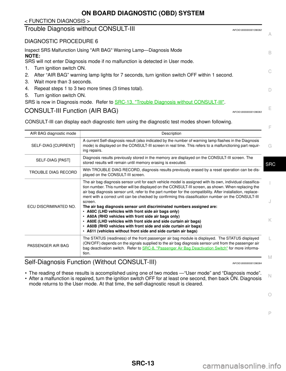
Trouble Diagnosis without CONSULT-IIIINFOID:0000000001396362
DIAGNOSTIC PROCEDURE 6
Inspect SRS Malfunction Using "AIR BAG" Warning Lamp—Diagnosis Mode
NOTE:
SRS will not enter Diagnosis mode if no malfunction is detected in User mode.
1. Turn ignition switch ON.
2. After “AIR BAG” warning lamp lights for 7 seconds, turn ignition switch OFF within 1 second.
3. Wait more than 3 seconds.
4. Repeat steps 1 to 3 two more times (3 times total).
5. Turn ignition switch ON.
SRS is now in Diagnosis mode. Refer to SRC-13, "
Trouble Diagnosis without CONSULT-III".
CONSULT-III Function (AIR BAG)INFOID:0000000001396363
CONSULT-III can display each diagnostic item using the diagnostic test modes shown following.
Self-Diagnosis Function (Without CONSULT-III)INFOID:0000000001396364
The reading of these results is accomplished using one of two modes —“User mode” and “Diagnosis mode”.
After a malfunction is repaired, turn the ignition switch OFF for at least one second, then back ON. Diagnosis
mode returns to the User mode. At that time, the self-diagnostic result is cleared.
AIR BAG diagnostic mode Description
SELF-DIAG [CURRENT]A current Self-diagnosis result (also indicated by the number of warning lamp flashes in the Diagnosis
mode) is displayed on the CONSULT-III screen in real time. This refers to a malfunctioning part requir-
ing repairs.
SELF-DIAG [PAST]Diagnosis results previously stored in the memory are displayed on the CONSULT-III screen. The
stored results will remain until memory erasing is executed.
TROUBLE DIAG RECORDWith TROUBLE DIAG RECORD, diagnosis results previously erased by a reset operation can be dis-
played on the CONSULT-III screen.
ECU DISCRIMINATED NO.The air bag diagnosis sensor unit for each vehicle model is assigned with its own, individual classifica-
tion number. This number will be displayed on the CONSULT-III screen, as shown. When replacing the
air bag diagnosis sensor unit, refer to the part number for the compatibility. After installation, replace-
ment with a correct unit can be checked by confirming this classification number on the CONSULT-III
screen.
The air bag diagnosis sensor unit discriminated numbers assigned are:
A60C (LHD vehicles with front side air bags only)
A60A (RHD vehicles with front side air bags only)
A60E (LHD vehicles with front side and side curtain air bags)
A60B (RHD vehicles with front side and side curtain air bags)
A611 (vehicles without front side and side curtain air bags)
PASSENGER AIR BAGThe STATUS (readiness) of the front passenger air bag module is displayed. The STATUS displayed
(ON/OFF) depends on the signals supplied to the air bag diagnosis sensor unit from the passenger air
bag deactivation switch. Refer to SRC-8, "
Passenger Air Bag Deactivation Switch" for more informa-
tion.
Page 4785 of 5883

SRC-16
< COMPONENT DIAGNOSIS >
B1049 - B1052 DRIVER AIR BAG MODULE
3.DTC
If DTC is detected. Refer to SRC-16, "
DiagnosisProcedure(Componentdiagnosis)".
>>END
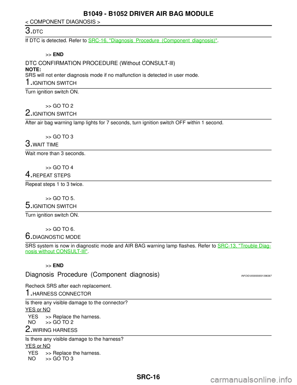
DTC CONFIRMATION PROCEDURE (Without CONSULT-lll)
NOTE:
SRS will not enter diagnosis mode if no malfunction is detected in user mode.
1.IGNITION SWITCH
Turn ignition switch ON.
>> GO TO 2
2.IGNITION SWITCH
After air bag warning lamp lights for 7 seconds, turn ignition switch OFF within 1 second.
>> GO TO 3
3.WAIT TIME
Wait more than 3 seconds.
>> GO TO 4
4.REPEAT STEPS
Repeat steps 1 to 3 twice.
>> GO TO 5.
5.IGNITION SWITCH
Turn ignition switch ON.
>> GO TO 6.
6.DIAGNOSTIC MODE
SRS system is now in diagnostic mode and AIR BAG warning lamp flashes. Refer to SRC-13, "
Trouble Diag-
nosis without CONSULT-III".
>>END
Diagnosis Procedure (Component diagnosis)INFOID:0000000001396367
Recheck SRS after each replacement.
1.HARNESS CONNECTOR
Is there any visible damage to the connector?
YES or NO
YES >> Replace the harness.
NO >> GO TO 2
2.WIRING HARNESS
Is there any visible damage to the harness?
YES or NO
YES >> Replace the harness.
NO >> GO TO 3
Page 4788 of 5883

B1065 - B1068 PASSENGER AIR BAG MODULE
SRC-19
< COMPONENT DIAGNOSIS >
C
D
E
F
G
I
J
K
L
MA
B
SRC
N
O
P
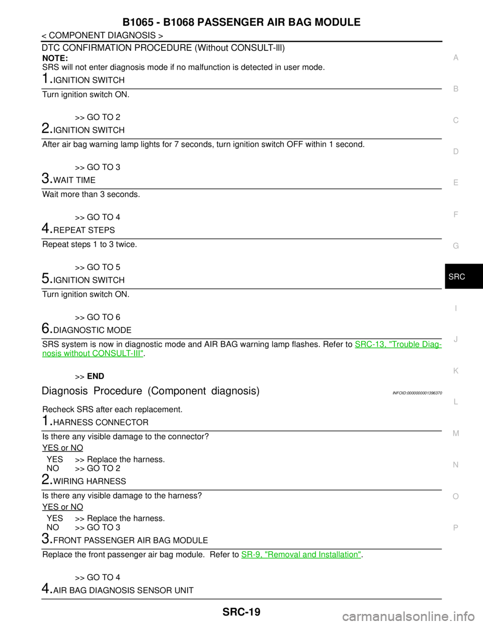
DTC CONFIRMATION PROCEDURE (Without CONSULT-lll)
NOTE:
SRS will not enter diagnosis mode if no malfunction is detected in user mode.
1.IGNITION SWITCH
Turn ignition switch ON.
>> GO TO 2
2.IGNITION SWITCH
After air bag warning lamp lights for 7 seconds, turn ignition switch OFF within 1 second.
>> GO TO 3
3.WAIT TIME
Wait more than 3 seconds.
>> GO TO 4
4.REPEAT STEPS
Repeat steps 1 to 3 twice.
>> GO TO 5
5.IGNITION SWITCH
Turn ignition switch ON.
>> GO TO 6
6.DIAGNOSTIC MODE
SRS system is now in diagnostic mode and AIR BAG warning lamp flashes. Refer to SRC-13, "
Trouble Diag-
nosis without CONSULT-III".
>>END
Diagnosis Procedure (Component diagnosis)INFOID:0000000001396370
Recheck SRS after each replacement.
1.HARNESS CONNECTOR
Is there any visible damage to the connector?
YES or NO
YES >> Replace the harness.
NO >> GO TO 2
2.WIRING HARNESS
Is there any visible damage to the harness?
YES or NO
YES >> Replace the harness.
NO >> GO TO 3
3.FRONT PASSENGER AIR BAG MODULE
Replace the front passenger air bag module. Refer to SR-9, "
Removal and Installation".
>> GO TO 4
4.AIR BAG DIAGNOSIS SENSOR UNIT
Page 4791 of 5883

SRC-22
< COMPONENT DIAGNOSIS >
B1134 – B1137 SIDE AIRBAG MODULE LH
DTC CONFIRMATION PROCEDURE (Without CONSULT-lll)
NOTE:
SRS will not enter diagnosis mode if no malfunction is detected in user mode.
1.IGNITION SWITCH
Turn ignition switch ON.
>> GO TO 2
2.IGNITION SWITCH
After air bag warning lamp lights for 7 seconds, turn ignition switch OFF within 1 second.
>> GO TO 3
3.WAIT TIME
Wait more than 3 seconds.
>> GO TO 4
4.REPEAT STEPS
Repeat steps 1 to 3 twice.
>> GO TO 5
5.IGNITION SWITCH
Turn ignition switch ON.
>> GO TO 6
6.DIAGNOSTIC MODE
SRS system is now in diagnostic mode and AIR BAG warning lamp flashes. Refer to SRC-13, "
Trouble Diag-
nosis without CONSULT-III".
>>END
Diagnosis Procedure (Component diagnosis)INFOID:0000000001396373
Recheck SRS after each replacement.
1.HARNESS CONNECTOR
Is there any visible damage to the connector?
YES or NO
YES >> Replace the harness.
NO >> GO TO 2
2.WIRING HARNESS
Is there any visible damage to the harness?
YES or NO
YES >> Replace the harness.
NO >> GO TO 3
3.FRONT LH SIDE AIR BAG MODULE
Replace the front LH seat back assembly. Refer to SE-14, "
Removal and Installation".
>> GO TO 4
4.AIR BAG DIAGNOSIS SENSOR UNIT
Page 4794 of 5883

B1129 – B1132 SIDE AIRBAG MODULE RH
SRC-25
< COMPONENT DIAGNOSIS >
C
D
E
F
G
I
J
K
L
MA
B
SRC
N
O
P
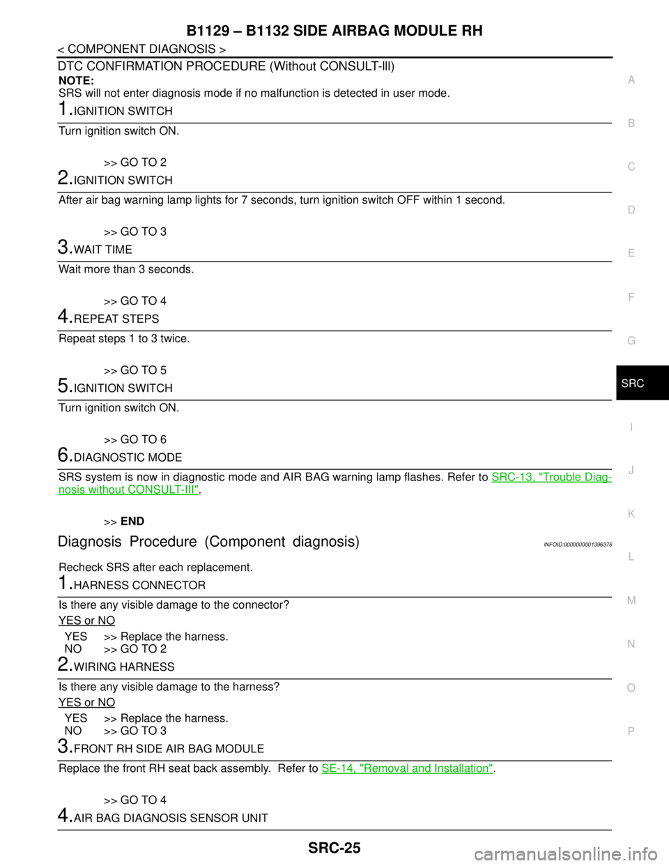
DTC CONFIRMATION PROCEDURE (Without CONSULT-lll)
NOTE:
SRS will not enter diagnosis mode if no malfunction is detected in user mode.
1.IGNITION SWITCH
Turn ignition switch ON.
>> GO TO 2
2.IGNITION SWITCH
After air bag warning lamp lights for 7 seconds, turn ignition switch OFF within 1 second.
>> GO TO 3
3.WAIT TIME
Wait more than 3 seconds.
>> GO TO 4
4.REPEAT STEPS
Repeat steps 1 to 3 twice.
>> GO TO 5
5.IGNITION SWITCH
Turn ignition switch ON.
>> GO TO 6
6.DIAGNOSTIC MODE
SRS system is now in diagnostic mode and AIR BAG warning lamp flashes. Refer to SRC-13, "
Trouble Diag-
nosis without CONSULT-III".
>>END
Diagnosis Procedure (Component diagnosis)INFOID:0000000001396376
Recheck SRS after each replacement.
1.HARNESS CONNECTOR
Is there any visible damage to the connector?
YES or NO
YES >> Replace the harness.
NO >> GO TO 2
2.WIRING HARNESS
Is there any visible damage to the harness?
YES or NO
YES >> Replace the harness.
NO >> GO TO 3
3.FRONT RH SIDE AIR BAG MODULE
Replace the front RH seat back assembly. Refer to SE-14, "
Removal and Installation".
>> GO TO 4
4.AIR BAG DIAGNOSIS SENSOR UNIT
Page 4797 of 5883

SRC-28
< COMPONENT DIAGNOSIS >
B1150 – B1153 SIDE CURTAIN AIR BAG MODULE LH
DTC CONFIRMATION PROCEDURE (Without CONSULT-lll)
NOTE:
SRS will not enter diagnosis mode if no malfunction is detected in user mode.
1.IGNITION SWITCH
Turn ignition switch ON.
>> GO TO 2
2.IGNITION SWITCH
After air bag warning lamp lights for 7 seconds, turn ignition switch OFF within 1 second.
>> GO TO 3
3.WAIT TIME
Wait more than 3 seconds.
>> GO TO 4
4.REPEAT STEPS
Repeat steps 1 to 3 twice.
>> GO TO 5
5.IGNITION SWITCH
Turn ignition switch ON.
>> GO TO 6
6.DIAGNOSTIC MODE
SRS system is now in diagnostic mode and AIR BAG warning lamp flashes. Refer to SRC-13, "
Trouble Diag-
nosis without CONSULT-III".
>>END
Diagnosis Procedure (Component diagnosis)INFOID:0000000001396379
Recheck SRS after each replacement.
1.HARNESS CONNECTOR
Is there any visible damage to the connector?
YES or NO
YES >> Replace the harness.
NO >> GO TO 2
2.WIRING HARNESS
Is there any visible damage to the harness?
YES or NO
YES >> Replace the harness.
NO >> GO TO 3
3.LH SIDE CURTAIN AIR BAG MODULE
Replace the LH side curtain air bag module. Refer to SR-10, "
Removal and Installation".
>> GO TO 4
4.AIR BAG DIAGNOSIS SENSOR UNIT