Page 4910 of 5883
![NISSAN TIIDA 2007 Service Repair Manual STC-36
< PRECAUTION >[EPS]
PRECAUTIONS
PRECAUTION
PRECAUTIONS
Precaution for Supplemental Restraint System (SRS) "AIR BAG" and "SEAT BELT
PRE-TENSIONER"
INFOID:0000000001697712
The Supplemental Restr](/manual-img/5/57395/w960_57395-4909.png "NISSAN TIIDA 2007 Service Repair Manual STC-36
< PRECAUTION >[EPS]
PRECAUTIONS
PRECAUTION
PRECAUTIONS
Precaution for Supplemental Restraint System (SRS) \"AIR BAG\" and \"SEAT BELT
PRE-TENSIONER\"
INFOID:0000000001697712
The Supplemental Restr")
STC-36
< PRECAUTION >[EPS]
PRECAUTIONS
PRECAUTION
PRECAUTIONS
Precaution for Supplemental Restraint System (SRS) "AIR BAG" and "SEAT BELT
PRE-TENSIONER"
INFOID:0000000001697712
The Supplemental Restraint System such as “AIR BAG” and “SEAT BELT PRE-TENSIONER”, used along
with a front seat belt, helps to reduce the risk or severity of injury to the driver and front passenger for certain
types of collision. Information necessary to service the system safely is included in the SR and SB section of
this Service Manual.
WARNING:
To avoid rendering the SRS inoperative, which could increase the risk of personal injury or death in
the event of a collision which would result in air bag inflation, all maintenance must be performed by
an authorized NISSAN/INFINITI dealer.
Improper maintenance, including incorrect removal and installation of the SRS, can lead to personal
injury caused by unintentional activation of the system. For removal of Spiral Cable and Air Bag
Module, see the SR section.
Do not use electrical test equipment on any circuit related to the SRS unless instructed to in this
Service Manual. SRS wiring harnesses can be identified by yellow and/or orange harnesses or har-
ness connectors.
Precaution Necessary for Steering Wheel Rotation After Battery Disconnect
INFOID:0000000001716731
NOTE:
This Procedure is applied only to models with Intelligent Key system and NATS (NISSAN ANTI-THEFT SYS-
TEM).
Remove and install all control units after disconnecting both battery cables with the ignition knob in the
″LOCK″ position.
Always use CONSULT-III to perform self-diagnosis as a part of each function inspection after finishing work.
If DTC is detected, perform trouble diagnosis according to self-diagnostic results.
For models equipped with the Intelligent Key system and NATS, an electrically controlled steering lock mech-
anism is adopted on the key cylinder.
For this reason, if the battery is disconnected or if the battery is discharged, the steering wheel will lock and
steering wheel rotation will become impossible.
If steering wheel rotation is required when battery power is interrupted, follow the procedure below before
starting the repair operation.
OPERATION PROCEDURE
1. Connect both battery cables.
NOTE:
Supply power using jumper cables if battery is discharged.
2. Use the Intelligent Key or mechanical key to turn the ignition switch to the ″ACC″ position. At this time, the
steering lock will be released.
3. Disconnect both battery cables. The steering lock will remain released and the steering wheel can be
rotated.
4. Perform the necessary repair operation.
5. When the repair work is completed, return the ignition switch to the ″LOCK″ position before connecting
the battery cables. (At this time, the steering lock mechanism will engage.)
6. Perform a self-diagnosis check of all control units using CONSULT-III.
Service Notice or Precaution for EPS SystemINFOID:0000000001697713
CAUTION:
Check or confirm the following item when performing the trouble diagnosis.
Check any possible causes by interviewing the symptom and it’s condition from the customer if any
malfunction, such as EPS warning lamp turns ON, occurs.
Check if air pressure and size of tires are proper, the specified part is used for the steering wheel,
and control unit is genuine part.
Page 5799 of 5883
WT-4
< SYMPTOM DIAGNOSIS >
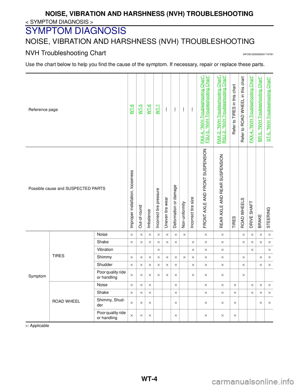
NOISE, VIBRATION AND HARSHNESS (NVH) TROUBLESHOOTING
SYMPTOM DIAGNOSIS
NOISE, VIBRATION AND HARSHNESS (NVH) TROUBLESHOOTING
NVH Troubleshooting ChartINFOID:0000000001716761
Use the chart below to help you find the cause of the symptom. If necessary, repair or replace these parts.
×: ApplicableReference page
WT-6WT-5
WT-6
WT-7—
—
—
—
FA X - 4 , "
NVH Troubleshooting Chart
",
FSU-5, "
NVH Troubleshooting Chart
"
RAX-2, "
NVH Troubleshooting Chart
",
RSU-2, "
NVH Troubleshooting Chart
"
Refer to TIRES in this chart
Refer to ROAD WHEEL in this chart
FAX-4, "
NVH Troubleshooting Chart
"
BR-5, "
NVH Troubleshooting Chart
"
ST-5, "
NVH Troubleshooting Chart
"
Possible cause and SUSPECTED PARTS
Improper installation, looseness
Out-of-round
Imbalance
Incorrect tire pressure
Uneven tire wear
Deformation or damage
Non-uniformity
Incorrect tire size
FRONT AXLE AND FRONT SUSPENSION
REAR AXLE AND REAR SUSPENSION
TIRES
ROAD WHEELS
DRIVE SHAFT
BRAKE
STEERING
SymptomTIRESNoise× ×××××× × × ××××
Shake× ××××× × × × ××××
Vibration××××××
Shimmy× ××××××× × × × ××
Shudder× ××××× × × × × ××
Poor quality ride
or handling× ××××× × × × ×
ROAD WHEELNoise× ×× × × × × ×××
Shake× ×× × × × × ×××
Shimmy, Shud-
der×××× ×××××
Poor quality ride
or handling××× × × × ×
Page 5802 of 5883
SERVICE DATA AND SPECIFICATIONS (SDS)
WT-7
< SERVICE DATA AND SPECIFICATIONS (SDS)
C
D
F
G
H
I
J
K
L
MA
B
WT
N
O
P
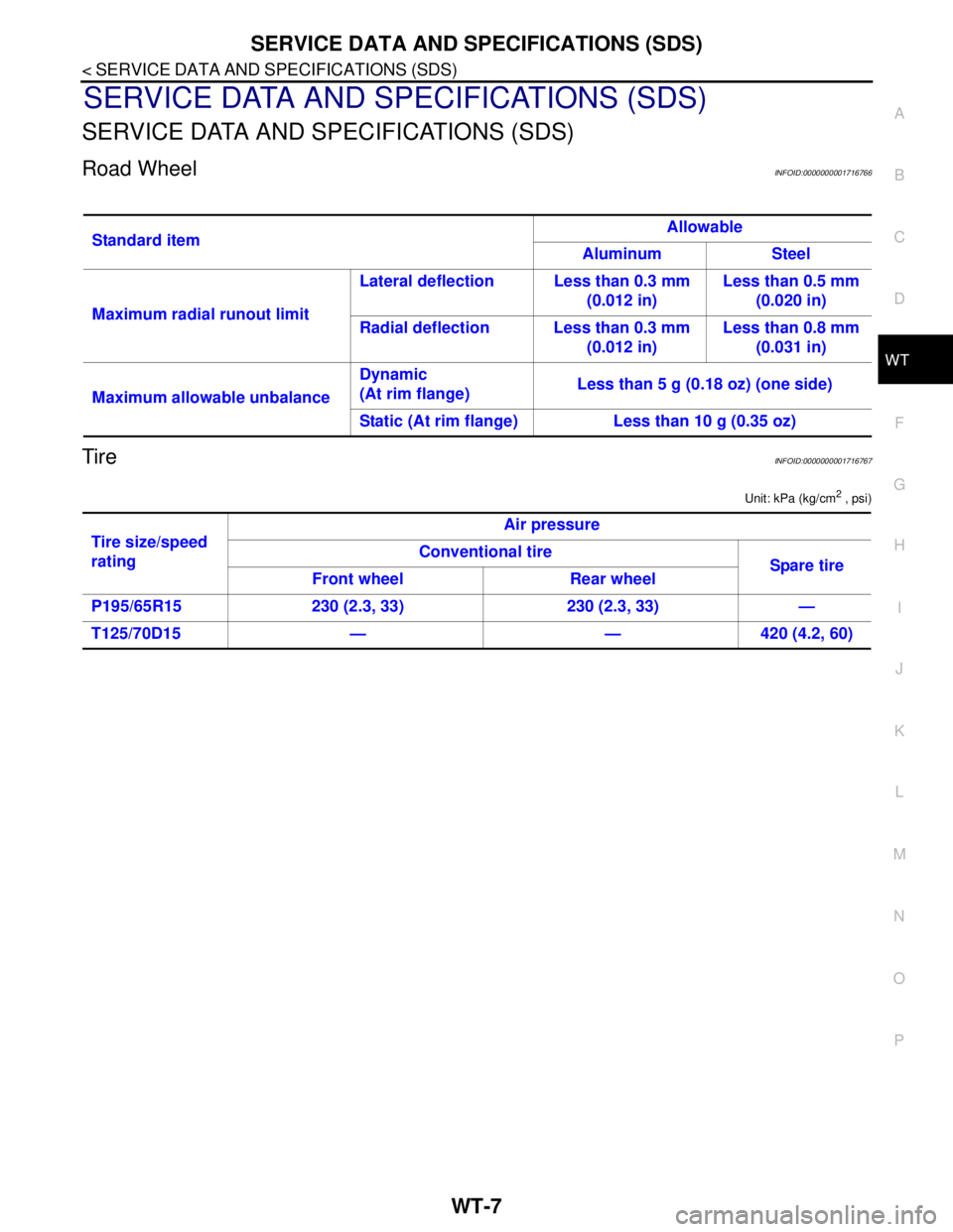
SERVICE DATA AND SPECIFICATIONS (SDS)
SERVICE DATA AND SPECIFICATIONS (SDS)
Road WheelINFOID:0000000001716766
TireINFOID:0000000001716767
Unit: kPa (kg/cm2 , psi)
Standard itemAllowable
Aluminum Steel
Maximum radial runout limitLateral deflection Less than 0.3 mm
(0.012 in)Less than 0.5 mm
(0.020 in)
Radial deflection Less than 0.3 mm
(0.012 in)Less than 0.8 mm
(0.031 in)
Maximum allowable unbalanceDynamic
(At rim flange)Less than 5 g (0.18 oz) (one side)
Static (At rim flange) Less than 10 g (0.35 oz)
Tire size/speed
ratingAir pressure
Conventional tire
Spare tire
Front wheel Rear wheel
P195/65R15 230 (2.3, 33) 230 (2.3, 33) —
T125/70D15 — — 420 (4.2, 60)
Page:
< prev 1-8 9-16 17-24