2007 NISSAN TIIDA starting system
[x] Cancel search: starting systemPage 445 of 5883
CHG-24
< COMPONENT DIAGNOSIS >[MR18DE]
B TERMINAL CIRCUIT
B TERMINAL CIRCUIT
DescriptionINFOID:0000000001724526
The terminal “1” (B) circuit supplies power to charge the battery and operate the vehicles electrical system.
Diagnosis ProcedureINFOID:0000000001724527
1.CHECK TERMINAL “1” CONNECTION
1. Turn ignition switch OFF.
2. Verify terminal “1” is clean and tight.
Is the inspection result normal?
YES >> GO TO 2
NO >> Repair terminal “1” connection. Confirm repair by performing complete Starting/Charging system
test. Refer to Technical Service Bulletin.
2.CHECK TERMINAL “1” CIRCUIT
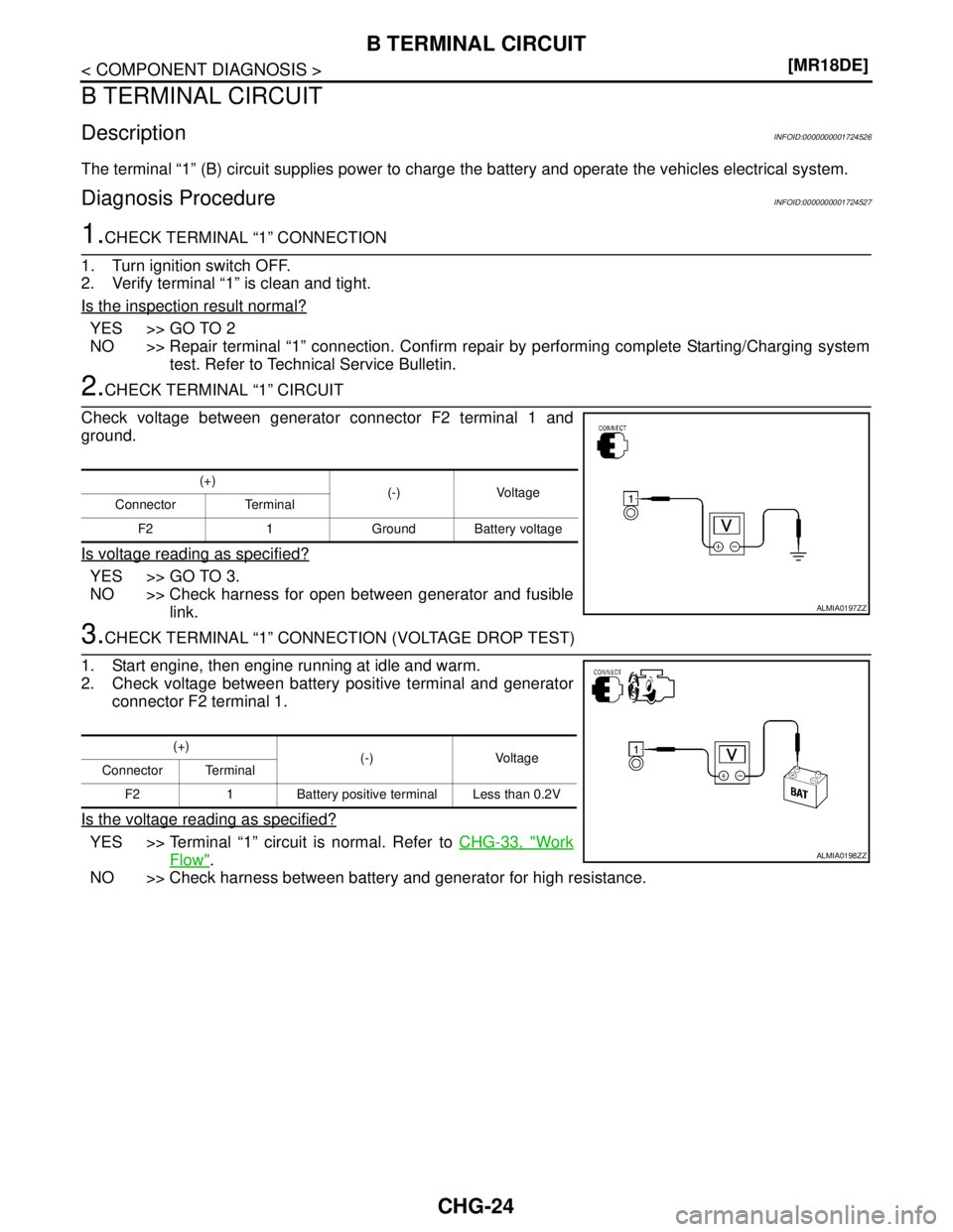
Check voltage between generator connector F2 terminal 1 and
ground.
Is voltage reading as specified?
YES >> GO TO 3.
NO >> Check harness for open between generator and fusible
link.
3.CHECK TERMINAL “1” CONNECTION (VOLTAGE DROP TEST)
1. Start engine, then engine running at idle and warm.
2. Check voltage between battery positive terminal and generator
connector F2 terminal 1.
Is the voltage reading as specified?
YES >> Terminal “1” circuit is normal. Refer to CHG-33, "Work
Flow".
NO >> Check harness between battery and generator for high resistance.
(+)
(-) Voltage
Connector Terminal
F2 1 Ground Battery voltage
ALMIA0197ZZ
(+)
(-) Voltage
Connector Terminal
F2 1 Battery positive terminal Less than 0.2V
ALMIA0198ZZ
Page 446 of 5883

CHG
L TERMINAL CIRCUIT
CHG-25
< COMPONENT DIAGNOSIS >[MR18DE]
C
D
E
F
G
H
I
J
K
L B A
O
P N
L TERMINAL CIRCUIT
DescriptionINFOID:0000000001724528
The terminal “2” (L) circuit controls the charge warning lamp. The charge warning lamp illuminates when the
ignition switch is set to ON or START. When the generator is providing sufficient voltage with the engine run-
ning, the charge warning lamp will go off. If the charge warning lamp illuminates with the engine running, a
malfunction is indicated.
Diagnosis ProcedureINFOID:0000000001724529
1.CHECK CHARGE WARNING LAMP CIRCUIT CONNECTION
Verify generator connector F2 terminal 2 is clean and tight.
Is the connection secure?
YES >> GO TO 2
NO >> Repair the connection. Confirm repair by performing complete Starting/Charging system test.
Refer to Technical Service Bulletin.
2.CHECK CHARGE WARNING LAMP CIRCUIT
1. Disconnect generator connector F2.
2. Apply ground to generator harness connector F2 terminal 2 with
the ignition switch in the ON position.
Does the charge lamp illuminate?
YES >> Check generator function. Refer to CHG-33, "Work
Flow".
NO >> GO TO 3
3.CHECK HARNESS CONTINUITY
1. Turn ignition switch OFF.
2. Disconnect the generator connector F2 and combination meter
connector M24.
3. Check continuity between generator harness connector F2 (A)
terminal 2 and combination meter harness connector M24 (B)
terminal 38.
4. Check continuity between generator harness connector F2 ter-
minal 2 and ground.
Are the continuity results as specified?
YES >> Replace the combination meter. Refer to XX-XX, "*****".
NO >> Repair the harness or connector.Charge lamp should illuminate
ALMIA0200ZZ
AB
Continuity
Connector Terminal Connector Terminal
F2 2 M24 38 Yes
A
—
Continuity
Connector Terminal
F2 2 Ground No
ALMIA0326GB
Page 447 of 5883
CHG-26
< COMPONENT DIAGNOSIS >[MR18DE]
S TERMINAL CIRCUIT
S TERMINAL CIRCUIT
DescriptionINFOID:0000000001724530
The output voltage of the generator is controlled by the IC regulator at terminal “3” (S) detecting the input volt-
age. Terminal “3” circuit detects the battery voltage to adjust the generator output voltage with the IC regulator.
Diagnosis ProcedureINFOID:0000000001724531
1.CHECK VOLTAGE REGULATOR CIRCUIT CONNECTION
Check to see if connector F2 terminal 3 is clean and tight.
Is the inspection result normal?
YES >> GO TO 2
NO >> Repair terminal connection. Confirm repair by performing complete Starting/Charging system test.
Refer to Technical Service Bulletin.
2.CHECK VOLTAGE REGULATOR CIRCUIT
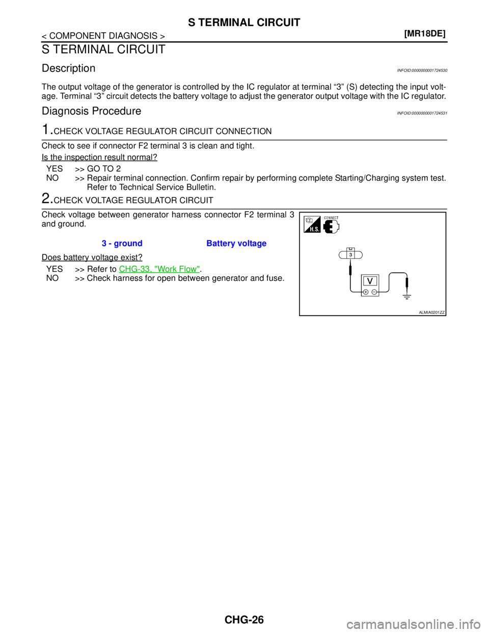
Check voltage between generator harness connector F2 terminal 3
and ground.
Does battery voltage exist?
YES >> Refer to CHG-33, "Work Flow".
NO >> Check harness for open between generator and fuse.3 - ground Battery voltage
ALMIA0201ZZ
Page 455 of 5883

CHG-34
< BASIC INSPECTION >[K9K]
DIAGNOSIS AND REPAIR WORKFLOW
NOTE:
To ensure a complete and thorough diagnosis, the battery, starter and generator test segments must be done
as a set from start to finish.
1.PRELIMINARY INSPECTION
Perform the preliminary inspection. Refer to CHG-37, "
Inspection Procedure".
>> GO TO 2
2.DISABLE THE POWER GENERATION VOLTAGE VARIABLE CONTROL SYSTEM
Disable the power generation voltage variable control with either of the following procedures.
After selecting “ENGINE” on the “SELECT SYSTEM” screen of CONSULT-III, set the “ALTERNATOR DUTY”
value to 0 % by selecting “ALTERNATOR DUTY” with “Active Test”. Continue “Active Test” until the end of
inspection. (When the DUTY value is 0 or 100 %, the normal power generation is performed according to the
characteristic of the IC regulator of the generator.)
Turn the ignition switch OFF, disconnect the battery current sensor connector and leave it disconnected dur-
ing the course of the test.
NOTE:
Running the engine with the battery current sensor disconnected will cause DTC's (P1550-P1554) to set.
After finishing the inspection, connect the battery current sensor connector and erase the self-diagnostic
results history of the engine using CONSULT-III.
>> GO TO 3
3.DIAGNOSIS WITH STARTING/CHARGING SYSTEM TESTER
Perform the charging system test using Starting/Charging System Tester (J-44373). For details and operating
instructions, refer to Technical Service Bulletin.
Te s t r e s u l t
CHARGING SYSTEM NOMAL>>Charging system is normal and will also show “DIODE RIPPLE” test result.
NO CHARGING VOLTAGE>>GO TO 4
LOW CHARGING VOLTAGE>>GO TO 12
HIGH CHARGING VOLTAGE>>GO TO 14
DIODE RIPPLE NORMAL>>Diode ripple is OK and will also show “CHARGING VOLTAGE” test result.
EXCESS RIPPLE DETECTED>>Replace the generator. Perform “DIODE RIPPLE” test again using Starting/
Charging System Tester (J-44373) to confirm repair.
DIODE RIPPLE NOT DETECTED>>GO TO 4
4.INSPECTION WITH CHARGE WARNING LAMP (IGNITION SWITCH IS ON)
Turn the ignition switch ON.
Does the charge warning lamp illuminate?
YES >> GO TO 6
NO >> GO TO 5
5.TERMINAL“2” (OPEN) CIRCUIT INSPECTION
Check terminal “2” circuit for open circuits. Refer to CHG-39, "
Diagnosis Procedure".
Is the terminal
“2” circuit normal?
YES >> Replace generator.
NO >> Repair as needed.
6.INSPECTION WITH CHARGE WARNING LAMP (IDLING)
Start the engine and run it at idle.
Does the charge warning lamp turn OFF?
YES >> GO TO 9
NO >> GO TO 7
7.TERMINAL “2”(SHORT) CIRCUIT INSPECTION
Check terminal “2” circuit for short to ground. Refer to CHG-39, "
Diagnosis Procedure".
Is the terminal
“2” circuit normal?
Page 459 of 5883
CHG-38
< COMPONENT DIAGNOSIS >[K9K]
B TERMINAL CIRCUIT
B TERMINAL CIRCUIT
DescriptionINFOID:0000000001724509
The terminal “1” (B) circuit supplies power to charge the battery and operate the vehicles electrical system.
Diagnosis ProcedureINFOID:0000000001724510
1.CHECK TERMINAL “1” CONNECTION
1. Turn ignition switch OFF.
2. Verify terminal “1” is clean and tight.
Is the inspection result normal?
YES >> GO TO 2
NO >> Repair terminal “1” connection. Confirm repair by performing complete Starting/Charging system
test. Refer to Technical Service Bulletin.
2.CHECK TERMINAL “1” CIRCUIT
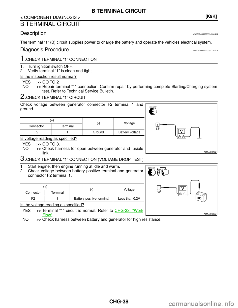
Check voltage between generator connector F2 terminal 1 and
ground.
Is voltage reading as specified?
YES >> GO TO 3.
NO >> Check harness for open between generator and fusible
link.
3.CHECK TERMINAL “1” CONNECTION (VOLTAGE DROP TEST)
1. Start engine, then engine running at idle and warm.
2. Check voltage between battery positive terminal and generator
connector F2 terminal 1.
Is the voltage reading as specified?
YES >> Terminal “1” circuit is normal. Refer to CHG-33, "Work
Flow".
NO >> Check harness between battery and generator for high resistance.
(+)
(-) Voltage
Connector Terminal
F2 1 Ground Battery voltage
ALMIA0197ZZ
(+)
(-) Voltage
Connector Terminal
F2 1 Battery positive terminal Less than 0.2V
ALMIA0198ZZ
Page 460 of 5883

CHG
L TERMINAL CIRCUIT
CHG-39
< COMPONENT DIAGNOSIS >[K9K]
C
D
E
F
G
H
I
J
K
L B A
O
P N
L TERMINAL CIRCUIT
DescriptionINFOID:0000000001724511
The terminal “2” (L) circuit controls the charge warning lamp. The charge warning lamp illuminates when the
ignition switch is set to ON or START. When the generator is providing sufficient voltage with the engine run-
ning, the charge warning lamp will go off. If the charge warning lamp illuminates with the engine running, a
malfunction is indicated.
Diagnosis ProcedureINFOID:0000000001724512
1.CHECK CHARGE WARNING LAMP CIRCUIT CONNECTION
Verify generator connector F1 terminal 2 is clean and tight.
Is the connection secure?
YES >> GO TO 2
NO >> Repair the connection. Confirm repair by performing complete Starting/Charging system test.
Refer to Technical Service Bulletin.
2.CHECK CHARGE WARNING LAMP CIRCUIT
1. Disconnect generator connector F1.
2. Apply ground to generator harness connector F1 terminal 2 with
the ignition switch in the ON position.
Does the charge lamp illuminate?
YES >> Check generator function. Refer to CHG-33, "Work
Flow".
NO >> GO TO 3
3.CHECK HARNESS CONTINUITY
1. Turn ignition switch OFF.
2. Disconnect the generator connector F1 and combination meter
connector M24.
3. Check continuity between generator harness connector F1 ter-
minal 2 and combination meter harness connector M24 terminal
38.
4. Check continuity between generator harness connector F1 ter-
minal 2 and ground.
Are the continuity results as specified?
YES >> Replace the combination meter. Refer to XX-XX, "*****".
NO >> Repair the harness or connector.Charge lamp should illuminate
ALMIA0328GB
Terminal Terminal
Continuity
Connector Terminal Connector Terminal
F1 2 M24 38 Yes
Te r , m i n a l
—
Continuity
Connector Terminal
F1 2 Ground No
ALMIA0329GB
Page 461 of 5883

CHG-40
< COMPONENT DIAGNOSIS >[K9K]
S TERMINAL CIRCUIT
S TERMINAL CIRCUIT
DescriptionINFOID:0000000001724513
The output voltage of the generator is controlled by the IC regulator at terminal “3” (S) detecting the input volt-
age. Terminal “3” circuit detects the battery voltage to adjust the generator output voltage with the IC regulator.
Diagnosis ProcedureINFOID:0000000001724514
1.CHECK VOLTAGE REGULATOR CIRCUIT CONNECTION
Check to see if connector F1 terminal 3 is clean and tight.
Is the inspection result normal?
YES >> GO TO 2
NO >> Repair terminal connection. Confirm repair by performing complete Starting/Charging system test.
Refer to Technical Service Bulletin.
2.CHECK VOLTAGE REGULATOR CIRCUIT
1. Disconnect generator harness connector F1.
2. Turn ignition switch ON.
3. Check voltage between generator harness connector F1 termi-
nal 3 and ground.
Does battery voltage exist?
YES >> Refer to CHG-33, "Work Flow".
NO >> Check harness for open between generator and fuse.3 - ground Battery voltage
ALMIA0330GB
Page 489 of 5883

CO-8
< PRECAUTION >[HR16DE]
PRECAUTIONS
PRECAUTION
PRECAUTIONS
Precaution for Supplemental Restraint System (SRS) "AIR BAG" and "SEAT BELT
PRE-TENSIONER"
INFOID:0000000001534589
The Supplemental Restraint System such as “AIR BAG” and “SEAT BELT PRE-TENSIONER”, used along
with a front seat belt, helps to reduce the risk or severity of injury to the driver and front passenger for certain
types of collision. Information necessary to service the system safely is included in the SR and SB section of
this Service Manual.
WARNING:
• To avoid rendering the SRS inoperative, which could increase the risk of personal injury or death in
the event of a collision which would result in air bag inflation, all maintenance must be performed by
an authorized NISSAN/INFINITI dealer.
Improper maintenance, including incorrect removal and installation of the SRS, can lead to personal
injury caused by unintentional activation of the system. For removal of Spiral Cable and Air Bag
Module, see the SR section.
Do not use electrical test equipment on any circuit related to the SRS unless instructed to in this
Service Manual. SRS wiring harnesses can be identified by yellow and/or orange harnesses or har-
ness connectors.
Precaution Necessary for Steering Wheel Rotation After Battery Disconnect
INFOID:0000000001534590
NOTE:
This Procedure is applied only to models with Intelligent Key system and NATS (NISSAN ANTI-THEFT SYS-
TEM).
Remove and install all control units after disconnecting both battery cables with the ignition knob in the
″LOCK″ position.
Always use CONSULT-II to perform self-diagnosis as a part of each function inspection after finishing work.
If DTC is detected, perform trouble diagnosis according to self-diagnostic results.
For models equipped with the Intelligent Key system and NATS, an electrically controlled steering lock mech-
anism is adopted on the key cylinder.
For this reason, if the battery is disconnected or if the battery is discharged, the steering wheel will lock and
steering wheel rotation will become impossible.
If steering wheel rotation is required when battery power is interrupted, follow the procedure below before
starting the repair operation.
OPERATION PROCEDURE
1. Connect both battery cables.
NOTE:
Supply power using jumper cables if battery is discharged.
2. Use the Intelligent Key or mechanical key to turn the ignition switch to the ″ACC″ position. At this time, the
steering lock will be released.
3. Disconnect both battery cables. The steering lock will remain released and the steering wheel can be
rotated.
4. Perform the necessary repair operation.
5. When the repair work is completed, return the ignition switch to the ″LOCK″ position before connecting
the battery cables. (At this time, the steering lock mechanism will engage.)
6. Perform a self-diagnosis check of all control units using CONSULT-II.
Precaution for Liquid GasketINFOID:0000000001534591
REMOVAL OF LIQUID GASKET SEALING
After removing nuts and bolts, separate the mating surface, using Tool and remove old liquid gasket sealing.