2007 NISSAN TIIDA mileage
[x] Cancel search: mileagePage 4257 of 5883

PERIODIC MAINTENANCE
MA-17
< ON-VEHICLE MAINTENANCE >
C
D
E
F
G
H
I
J
K
L
MB
MAN
OA
NOTE:
(1) Inspect once per year.
Maintenance items with “ ” should be performed more frequently according to “Maintenance Under Severe Driving Con-
ditions”.
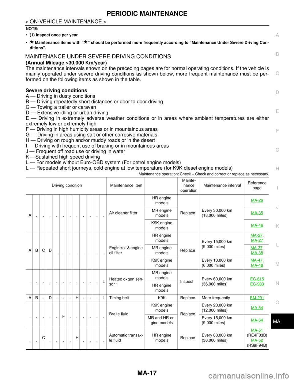
MAINTENANCE UNDER SEVERE DRIVING CONDITIONS
(Annual Mileage >30,000 Km/year)
The maintenance intervals shown on the preceding pages are for normal operating conditions. If the vehicle is
mainly operated under severe driving conditions as shown below, more frequent maintenance must be per-
formed on the following items as shown in the table.
Severe driving conditions
A — Driving in dusty conditions
B — Driving repeatedly short distances or door to door driving
C — Towing a trailer or caravan
D — Extensive idling or urban driving
E — Driving in extremely adverse weather conditions or in areas where ambient temperatures are either
extremely low or extremely high
F — Driving in high humidity areas or in mountainous areas
G — Driving in areas using salt or other corrosive materials
H — Driving on rough and/or muddy roads or in the desert
I — Driving with frequent use of braking or in mountainous areas
J — Frequent off road use or driving in water
K —Sustained high speed driving
L — For models without Euro-OBD system (For petrol engine models)
L — Repeated short journeys, cold engine at low temperature (for K9K diesel engine models)
Maintenance operation: Check = Check and correct or replace as necessary.
Driving condition Maintenance itemMainte-
nance
operationMaintenance intervalReference
page
A...........Air cleaner filterHR engine
models
ReplaceEvery 30,000 km
(18,000 miles) MA-26
MR engine
modelsMA-35
K9K engine
modelsMA-46
ABCD
........Engine oil & engine
oil filter HR engine
models
ReplaceEvery 15,000 km
(9,000 miles) MA-27
,
MA-27
MR engine
modelsMA-37,
MA-38
K9K engine
modelsEvery 10,000 km
(6,000 miles) MA-47,
MA-48
...........LHeated oxgen sen-
sor 1MR engine
models
InspectEvery 60,000 km
(36,000 miles) EC-615EC-903HR engine
models
A B . D . . . H . . . L Timing belt K9K Replace More frequentlyEM-291
.....F......Brake fluidK9K engine
models
ReplaceEvery 20,000 km
(12,000 miles) MA-54MR and HR en-
gine modelsEvery 15,000 km
(9,000 miles) MA-54
..C
....H
....Automatic transax-
le fluidHR engine
modelsReplaceEvery 60,000 km
(36,000 miles) MA-51
(RE4F03B)
MA-52
(RS9F94B)
Page 4320 of 5883

MWI
METER SYSTEM
MWI-13
< FUNCTION DIAGNOSIS >
C
D
E
F
G
H
I
J
K
L
MB A
O
P
FUEL GAUGE : Component DescriptionINFOID:0000000001537303
ODO/TRIP METER
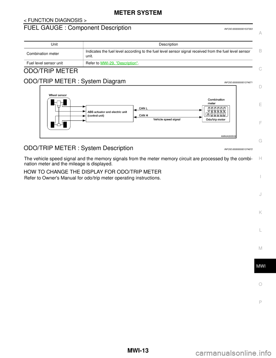
ODO/TRIP METER : System DiagramINFOID:0000000001374671
ODO/TRIP METER : System DescriptionINFOID:0000000001374672
The vehicle speed signal and the memory signals from the meter memory circuit are processed by the combi-
nation meter and the mileage is displayed.
HOW TO CHANGE THE DISPLAY FOR ODO/TRIP METER
Refer to Owner's Manual for odo/trip meter operating instructions.
Unit Description
Combination meterIndicates the fuel level according to the fuel level sensor signal received from the fuel level sensor
unit.
Fuel level sensor unit Refer to MWI-29, "
Description".
AWNIA0005GB
Page 4322 of 5883

MWI
METER SYSTEM
MWI-15
< FUNCTION DIAGNOSIS >
C
D
E
F
G
H
I
J
K
L
MB A
O
P
ODO/TRIP METER : Component DescriptionINFOID:0000000001537302
WARNING LAMPS/INDICATOR LAMPS
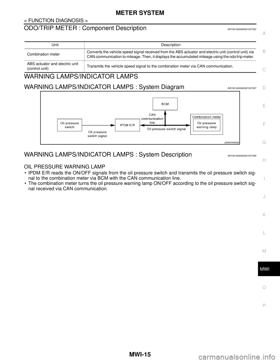
WARNING LAMPS/INDICATOR LAMPS : System DiagramINFOID:0000000001537297
WARNING LAMPS/INDICATOR LAMPS : System DescriptionINFOID:0000000001537298
OIL PRESSURE WARNING LAMP
IPDM E/R reads the ON/OFF signals from the oil pressure switch and transmits the oil pressure switch sig-
nal to the combination meter via BCM with the CAN communication line.
The combination meter turns the oil pressure warning lamp ON/OFF according to the oil pressure switch sig-
nal received via CAN communication.
Unit Description
Combination meterConverts the vehicle speed signal received from the ABS actuator and electric unit (control unit) via
CAN communication to mileage. Then, it displays the accumulated mileage using the odo/trip meter.
ABS actuator and electric unit
(control unit)Transmits the vehicle speed signal to the combination meter via CAN communication.
JSNIA0449GB
Page 4957 of 5883
![NISSAN TIIDA 2007 Service Repair Manual DIAGNOSIS AND REPAIR WORKFLOW
TM-11
< BASIC INSPECTION >[TYPE 1 (4AT: RE4F03B)]
C
E
F
G
H
I
J
K
L
MA
B
TM
N
O
P
>> GO TO 3.
3.CHECK DTC
1. Check DTC.
2. Perform the following procedure if DTC is detec NISSAN TIIDA 2007 Service Repair Manual DIAGNOSIS AND REPAIR WORKFLOW
TM-11
< BASIC INSPECTION >[TYPE 1 (4AT: RE4F03B)]
C
E
F
G
H
I
J
K
L
MA
B
TM
N
O
P
>> GO TO 3.
3.CHECK DTC
1. Check DTC.
2. Perform the following procedure if DTC is detec](/manual-img/5/57395/w960_57395-4956.png)
DIAGNOSIS AND REPAIR WORKFLOW
TM-11
< BASIC INSPECTION >[TYPE 1 (4AT: RE4F03B)]
C
E
F
G
H
I
J
K
L
MA
B
TM
N
O
P
>> GO TO 3.
3.CHECK DTC
1. Check DTC.
2. Perform the following procedure if DTC is detected.
Record DTC.
Erase DTC. Refer to TM-35, "
CONSULT-III Function (TRANSMISSION)".
Is any DTC detected?
YES >> GO TO 4.
NO >> GO TO 6.
4.PERFORM DIAGNOSTIC PROCEDURE
Perform “Diagnosis Procedure” for the displayed DTC.
>> GO TO 5.
5.PERFORM DTC CONFIRMATION PROCEDURE
Perform “DTC CONFIRMATION PROCEDURE”.
Is DTC detected?
YES >> GO TO 4.
NO >> GO TO 6.
6.CHECK SYMPTOM 2
Try to confirm the symptom described by the customer.
Is any malfunction present?
YES >> GO TO 7.
NO >> INSPECTION END
7.ROAD TEST
Perform “ROAD TEST”. Refer to TM-180, "
Description".
>> GO TO 8.
8.CHECK SYMPTOM 3
Try to confirm the symptom described by the customer.
Is any malfunction present?
YES >> GO TO 2.
NO >> INSPECTION END
Diagnostic Work SheetINFOID:0000000001728291
INFORMATION FROM CUSTOMER
KEY POINTSWHAT..... Vehicle and A/T model
WHEN..... Date, Frequencies
WHERE..... Road conditions
HOW..... Operating conditions, Symptoms
Customer name MR/MS Model and Year VIN
Trans. Model Engine Mileage
Malfunction Date Manuf. Date In Service Date
Frequency❏ Continuous❏ Intermittent ( times a day)
Page 5111 of 5883
![NISSAN TIIDA 2007 Service Repair Manual PRECAUTIONS
TM-165
< PRECAUTION >[TYPE 1 (4AT: RE4F03B)]
C
E
F
G
H
I
J
K
L
MA
B
TM
N
O
P
Before assembly, apply a coat of recommended ATF to all parts. Apply petroleum jelly to protect O-rings and
s NISSAN TIIDA 2007 Service Repair Manual PRECAUTIONS
TM-165
< PRECAUTION >[TYPE 1 (4AT: RE4F03B)]
C
E
F
G
H
I
J
K
L
MA
B
TM
N
O
P
Before assembly, apply a coat of recommended ATF to all parts. Apply petroleum jelly to protect O-rings and
s](/manual-img/5/57395/w960_57395-5110.png)
PRECAUTIONS
TM-165
< PRECAUTION >[TYPE 1 (4AT: RE4F03B)]
C
E
F
G
H
I
J
K
L
MA
B
TM
N
O
P
Before assembly, apply a coat of recommended ATF to all parts. Apply petroleum jelly to protect O-rings and
seals, or hold bearings and washers in place during assembly. Do not use grease.
Extreme care should be taken to avoid damage to O-rings, seals and gaskets when assembling.
After overhaul, refill the A/T with new ATF.
When the A/T drain plug is removed, only some of the fluid is drained. Old A/T fluid will remain in torque con-
verter and ATF cooling system.
Always follow the procedures under “Changing A/T Fluid” in the AT section when changing A/T fluid. Refer to
XX-XX, "*****"
, XX-XX, "*****".
Service Notice or PrecautionINFOID:0000000001696268
TORQUE CONVERTER SERVICE
The torque converter should be replaced under any of the following conditions:
External leaks in the hub weld area.
Converter hub is scored or damaged.
Converter pilot is broken, damaged or fits poorly into crankshaft.
Steel particles are found after flushing the cooler and cooler lines.
Pump is damaged or steel particles are found in the converter.
Vehicle has TCC shudder and/or no TCC apply. Replace only after all hydraulic and electrical diagnoses
have been made. (Converter clutch material may be glazed.)
Converter is contaminated with engine coolant containing antifreeze.
Internal malfunction of stator roller clutch.
Heavy clutch debris due to overheating (blue converter).
Steel particles or clutch lining material found in fluid filter or on magnet when no internal parts in unit are
worn or damaged — indicates that lining material came from converter.
The torque converter should not be replaced if:
The fluid has an odor, is discolored, and there is no evidence of metal or clutch facing particles.
The threads in one or more of the converter bolt holes are damaged.
A/T malfunction did not display evidence of damaged or worn internal parts, steel particles or clutch plate lin-
ing material in unit and inside the fluid filter.
Vehicle has been exposed to high mileage (only). The exception may be where the torque converter clutch
dampener plate lining has seen excess wear by vehicles operated in heavy and/or constant traffic, such as
taxi, delivery or police use.
OBD SELF-DIAGNOSIS (FOR TYPE 1 ONLY)
A/T self-diagnosis is performed by the TCM in combination with the ECM. The results can be read through
the blinking pattern of the OD OFF indicator lamp or the malfunction indicator lamp (MIL). Refer to the table
on XX-XX, "*****"
for the indicator used to display each self-diagnostic result.
The self-diagnostic results indicated by the MIL are automatically stored in both the ECM and TCM memo-
ries.
Always perform the procedure “HOW TO ERASE DTC” on XX-XX, "*****"
to complete the repair and
avoid unnecessary blinking of the MIL.
The following self-diagnostic items can be detected using ECM self-diagnostic results mode* only when the
OD OFF indicator lamp does not indicate any malfunctions.
-PNP switch
- A/T 1st, 2nd, 3rd, or 4th gear function
*: For details of OBD, refer to XX-XX, "*****"
.
Wiring Diagram and Trouble DiagnosisINFOID:0000000001696269
When reading wiring diagrams, refer to the following:
XX-XX, "*****"
XX-XX, "*****"
When performing trouble diagnosis, refer to the following:
XX-XX, "*****"
XX-XX, "*****"
Page 5273 of 5883
![NISSAN TIIDA 2007 Service Repair Manual DIAGNOSIS AND REPAIR WORKFLOW
TM-327
< BASIC INSPECTION >[TYPE 2 (4AT: RE4F03B)]
C
E
F
G
H
I
J
K
L
MA
B
TM
N
O
P
>> GO TO 3.
3.ROAD TEST
Perform “ROAD TEST”. Refer to TM-482, "
Description".
>> GO NISSAN TIIDA 2007 Service Repair Manual DIAGNOSIS AND REPAIR WORKFLOW
TM-327
< BASIC INSPECTION >[TYPE 2 (4AT: RE4F03B)]
C
E
F
G
H
I
J
K
L
MA
B
TM
N
O
P
>> GO TO 3.
3.ROAD TEST
Perform “ROAD TEST”. Refer to TM-482, "
Description".
>> GO](/manual-img/5/57395/w960_57395-5272.png)
DIAGNOSIS AND REPAIR WORKFLOW
TM-327
< BASIC INSPECTION >[TYPE 2 (4AT: RE4F03B)]
C
E
F
G
H
I
J
K
L
MA
B
TM
N
O
P
>> GO TO 3.
3.ROAD TEST
Perform “ROAD TEST”. Refer to TM-482, "
Description".
>> GO TO 4.
4.PERFORM SELF-DIAGNOSTIC PROCEDURE
Perform “Self-Diagnosis Procedure”. Refer to TM-348, "
CONSULT-III Function (TRANSMISSION)" or TM-350,
"Diagnosis Procedure without CONSULT-III".
>> GO TO 5.
5.CHECK SYMPTOM 2
Try to confirm the symptom described by the customer.
Is any malfunction present?
YES >> GO TO 6.
NO >> INSPECTION END
6.CHECK SYMPTOM 3
Try to confirm the symptom described by the customer.
Is any malfunction present?
YES >> GO TO 2.
NO >> INSPECTION END
Diagnostic Work SheetINFOID:0000000001728327
INFORMATION FROM CUSTOMER
KEY POINTSWHAT..... Vehicle and A/T model
WHEN..... Date, Frequencies
WHERE..... Road conditions
HOW..... Operating conditions, Symptoms
DIAGNOSTIC WORK SHEET
Customer name MR/MS Model and Year VIN
Trans. Model Engine Mileage
Malfunction Date Manuf. Date In Service Date
Frequency❏ Continuous❏ Intermittent ( times a day)
Symptoms❏ Vehicle does not move. (❏ Any position❏ Particular position)
❏ No up-shift (❏ 1st → 2nd❏ 2nd → 3rd❏ 3rd → 4th ❏ 4th → 5th)
❏ No down-shift (❏ 5th → 4th ❏ 4th → 3rd❏ 3rd → 2nd❏ 2nd → 1st)
❏ Lock-up malfunction
❏ Shift point too high or too low.
❏ Shift shock or slip (❏ N → D❏ N → R❏ Lock-up❏ Any drive position)
❏ Noise or vibration
❏ No kick down
❏ No pattern select
❏ Others
()
Malfunction indicator lamp (MIL)❏ Continuously lit❏ Not lit
Page 5413 of 5883
![NISSAN TIIDA 2007 Service Repair Manual PRECAUTIONS
TM-467
< PRECAUTION >[TYPE 2 (4AT: RE4F03B)]
C
E
F
G
H
I
J
K
L
MA
B
TM
N
O
P
Before assembly, apply a coat of recommended ATF to all parts. Apply petroleum jelly to protect O-rings and
s NISSAN TIIDA 2007 Service Repair Manual PRECAUTIONS
TM-467
< PRECAUTION >[TYPE 2 (4AT: RE4F03B)]
C
E
F
G
H
I
J
K
L
MA
B
TM
N
O
P
Before assembly, apply a coat of recommended ATF to all parts. Apply petroleum jelly to protect O-rings and
s](/manual-img/5/57395/w960_57395-5412.png)
PRECAUTIONS
TM-467
< PRECAUTION >[TYPE 2 (4AT: RE4F03B)]
C
E
F
G
H
I
J
K
L
MA
B
TM
N
O
P
Before assembly, apply a coat of recommended ATF to all parts. Apply petroleum jelly to protect O-rings and
seals, or hold bearings and washers in place during assembly. Do not use grease.
Extreme care should be taken to avoid damage to O-rings, seals and gaskets when assembling.
After overhaul, refill the A/T with new ATF.
When the A/T drain plug is removed, only some of the fluid is drained. Old A/T fluid will remain in torque con-
verter and ATF cooling system.
Always follow the procedures under “Changing A/T Fluid” in the AT section when changing A/T fluid. Refer to
XX-XX, "*****"
, XX-XX, "*****".
Service Notice or PrecautionINFOID:0000000001723048
TORQUE CONVERTER SERVICE
The torque converter should be replaced under any of the following conditions:
External leaks in the hub weld area.
Converter hub is scored or damaged.
Converter pilot is broken, damaged or fits poorly into crankshaft.
Steel particles are found after flushing the cooler and cooler lines.
Pump is damaged or steel particles are found in the converter.
Vehicle has TCC shudder and/or no TCC apply. Replace only after all hydraulic and electrical diagnoses
have been made. (Converter clutch material may be glazed.)
Converter is contaminated with engine coolant containing antifreeze.
Internal malfunction of stator roller clutch.
Heavy clutch debris due to overheating (blue converter).
Steel particles or clutch lining material found in fluid filter or on magnet when no internal parts in unit are
worn or damaged — indicates that lining material came from converter.
The torque converter should not be replaced if:
The fluid has an odor, is discolored, and there is no evidence of metal or clutch facing particles.
The threads in one or more of the converter bolt holes are damaged.
A/T malfunction did not display evidence of damaged or worn internal parts, steel particles or clutch plate lin-
ing material in unit and inside the fluid filter.
Vehicle has been exposed to high mileage (only). The exception may be where the torque converter clutch
dampener plate lining has seen excess wear by vehicles operated in heavy and/or constant traffic, such as
taxi, delivery or police use.
OBD SELF-DIAGNOSIS (FOR TYPE 1 ONLY)
A/T self-diagnosis is performed by the TCM in combination with the ECM. The results can be read through
the blinking pattern of the OD OFF indicator lamp or the malfunction indicator lamp (MIL). Refer to the table
on XX-XX, "*****"
for the indicator used to display each self-diagnostic result.
The self-diagnostic results indicated by the MIL are automatically stored in both the ECM and TCM memo-
ries.
Always perform the procedure “HOW TO ERASE DTC” on XX-XX, "*****"
to complete the repair and
avoid unnecessary blinking of the MIL.
The following self-diagnostic items can be detected using ECM self-diagnostic results mode* only when the
OD OFF indicator lamp does not indicate any malfunctions.
-PNP switch
- A/T 1st, 2nd, 3rd, or 4th gear function
*: For details of OBD, refer to XX-XX, "*****"
.
Wiring Diagram and Trouble DiagnosisINFOID:0000000001723049
When reading wiring diagrams, refer to the following:
XX-XX, "*****"
XX-XX, "*****"
When performing trouble diagnosis, refer to the following:
XX-XX, "*****"
XX-XX, "*****"