2007 NISSAN TIIDA Def
[x] Cancel search: DefPage 212 of 5883

BR-20
< ON-VEHICLE REPAIR >
BRAKE BOOSTER
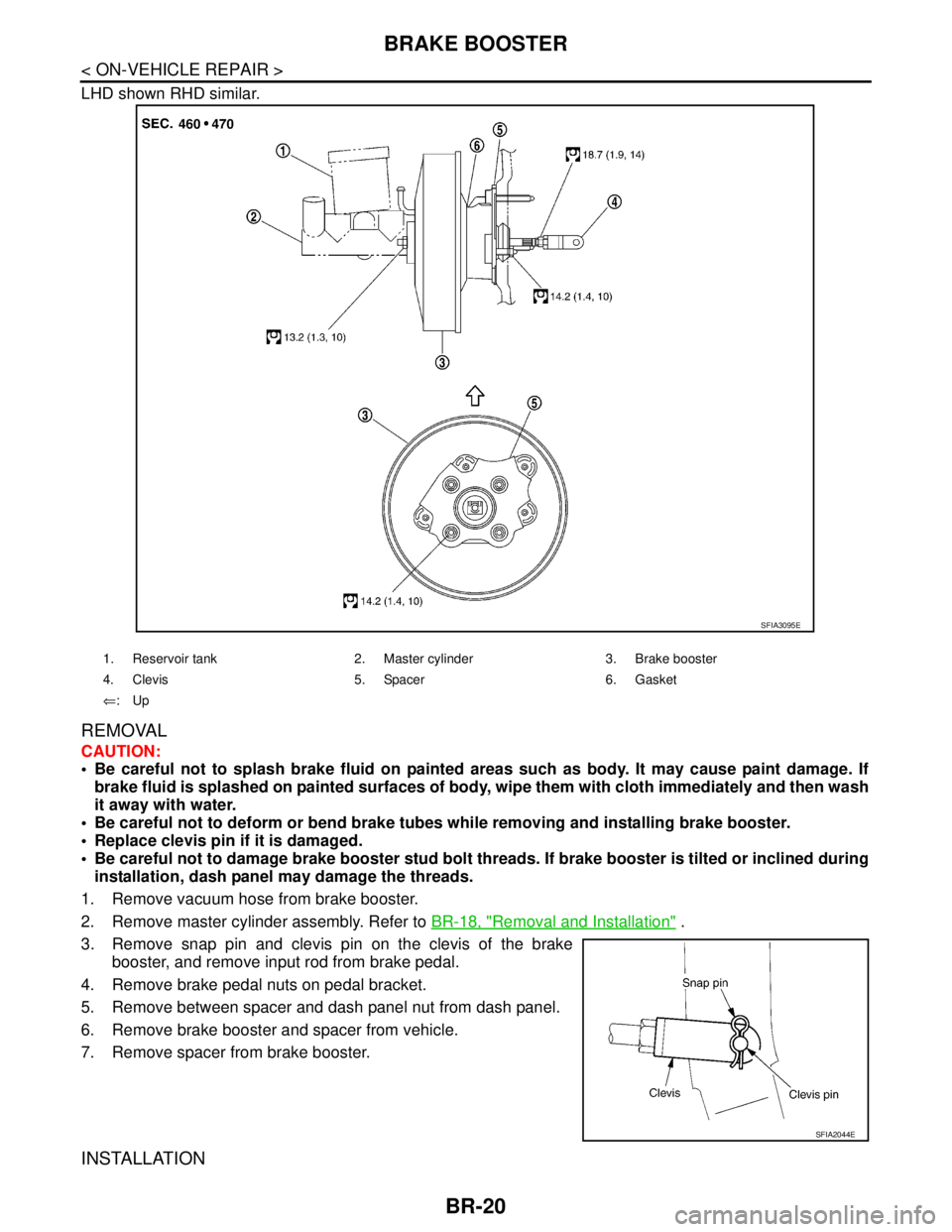
LHD shown RHD similar.
REMOVAL
CAUTION:
Be careful not to splash brake fluid on painted areas such as body. It may cause paint damage. If
brake fluid is splashed on painted surfaces of body, wipe them with cloth immediately and then wash
it away with water.
Be careful not to deform or bend brake tubes while removing and installing brake booster.
Replace clevis pin if it is damaged.
Be careful not to damage brake booster stud bolt threads. If brake booster is tilted or inclined during
installation, dash panel may damage the threads.
1. Remove vacuum hose from brake booster.
2. Remove master cylinder assembly. Refer to BR-18, "
Removal and Installation" .
3. Remove snap pin and clevis pin on the clevis of the brake
booster, and remove input rod from brake pedal.
4. Remove brake pedal nuts on pedal bracket.
5. Remove between spacer and dash panel nut from dash panel.
6. Remove brake booster and spacer from vehicle.
7. Remove spacer from brake booster.
INSTALLATION
1. Reservoir tank 2. Master cylinder 3. Brake booster
4. Clevis 5. Spacer 6. Gasket
⇐:Up
SFIA3095E
SFIA2044E
Page 215 of 5883

VACUUM LINES
BR-23
< ON-VEHICLE REPAIR >
C
D
E
G
H
I
J
K
L
MA
B
BR
N
O
P
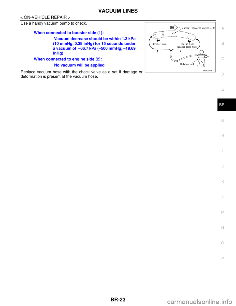
Use a handy vacuum pump to check.
Replace vacuum hose with the check valve as a set if damage or
deformation is present at the vacuum hose.When connected to booster side (1):
Vacuum decrease should be within 1.3 kPa
(10 mmHg, 0.39 inHg) for 15 seconds under
a vacuum of –66.7 kPa (–500 mmHg, –19.69
inHg)
When connected to engine side (2):
No vacuum will be applied
SFIA0210E
Page 217 of 5883

FRONT DISC BRAKE
BR-25
< ON-VEHICLE REPAIR >
C
D
E
G
H
I
J
K
L
MA
B
BR
N
O
P
2. Remove sliding pin bolt (lower side).
3. Hang cylinder body with a wire, and remove pads, shims and
pad retainers from torque member.
CAUTION:
When removing pad retainer from torque member, lift pad
retainer in the direction shown by arrow, so as not to
deform it.
INSTALLATION
1. Apply M-77 grease or equivalent to the shims. Install shims to pads.
CAUTION:
Securely install shims according to mounting direction of pads.
2. Apply M7439 grease or equivalent to pad contact surface on pad retainers. Install pad retainers and pads
to the torque member.
CAUTION:
When installing pad retainer, attach it firmly so that it is
not lifted up from torque member, as shown.
3. Install cylinder body to torque member.
NOTE:
Use a disc brake piston tool (commercial service tool) to easily press to piston in.
CAUTION:
Check the brake fluid level in the reservoir tank for fluid level because brake fluid returns to mas-
ter cylinder reservoir tank when pressing piston in.
4. Install lower sliding pin bolt (lower side), and tighten it to the specified torque. Refer to BR-24, "
Compo-
nent" .
5. Check brake for drag.
6. Install tires to the vehicle.
Removal and Installation of Brake Caliper AssemblyINFOID:0000000001717007
REMOVAL
1. Remove tires from vehicle.
2. Secure disc rotor using wheel nuts.
CAUTION:
Put matching marks on wheel hub assembly and disc rotor, if it is necessary to remove disc rotor.
3. Drain brake fluid. Refer to BR-8, "
Drain and Refill" .
SBR556E
PFIA0273E
Page 226 of 5883

BR-34
< DISASSEMBLY AND ASSEMBLY >
FRONT DISC BRAKE
FRONT DISC BRAKE
Disassembly and Assembly of Brake Caliper AssemblyINFOID:0000000001717023
NOTE:
Do not remove torque member, brake pads, shims and pad retainers, when disassembling or assembling cyl-
inder body.
DISASSEMBLY
1. Remove caliper assembly from vehicle. Refer to BR-25,
"Removal and Installation of Brake Caliper Assembly" .
2. Remove sliding pin bolts from cylinder body, and remove pads,
shims and pad retainers from torque member, if necessary.
CAUTION:
When removing pad retainer from torque member, lift the
pad retainer in the direction shown by arrow, so as not to
deform it.
3. Remove sliding pins and sliding pin boots from torque member.
4. Place a wooden block as shown, and blow air from union bolt
mounting hole to remove piston and piston boot.
CAUTION:
Do not get fingers caught in the piston.
5. Remove piston seal with a flat-bladed screwdriver.
CAUTION:
Be careful not to damage the inner wall of cylinder.
INSPECTION AFTER DISASSEMBLY
Cylinder Body
Check the inner wall of cylinder for corrosion, wear, and damage. Replace cylinder body as necessary.
CAUTION:
Clean cylinder body using new brake fluid. Never use mineral oils such as gasoline or kerosene.
Torque Member
Check for wear, cracks, and damage. Replace torque member as necessary..
Piston
Check piston surface for corrosion, wear, and damage. Replace piston as necessary.
CAUTION:
The piston sliding surface is plated. Do not polish with sandpaper.
Sliding Pin, Sliding Pin Bolt, and Sliding Pin Boot
SBR556E
WFIA0525E
SFIA2277E
Page 229 of 5883

REAR DISC BRAKE
BR-37
< DISASSEMBLY AND ASSEMBLY >
C
D
E
G
H
I
J
K
L
MA
B
BR
N
O
P
REAR DISC BRAKE
Disassembly and AssemblyINFOID:0000000001724669
DISASSEMBLY
1. Remove the sliding pin bolt, and then remove the pad, shim, shim cover, and pad retainer from the torque
member and cylinder.
2. Remove sliding pin boot from torque member.
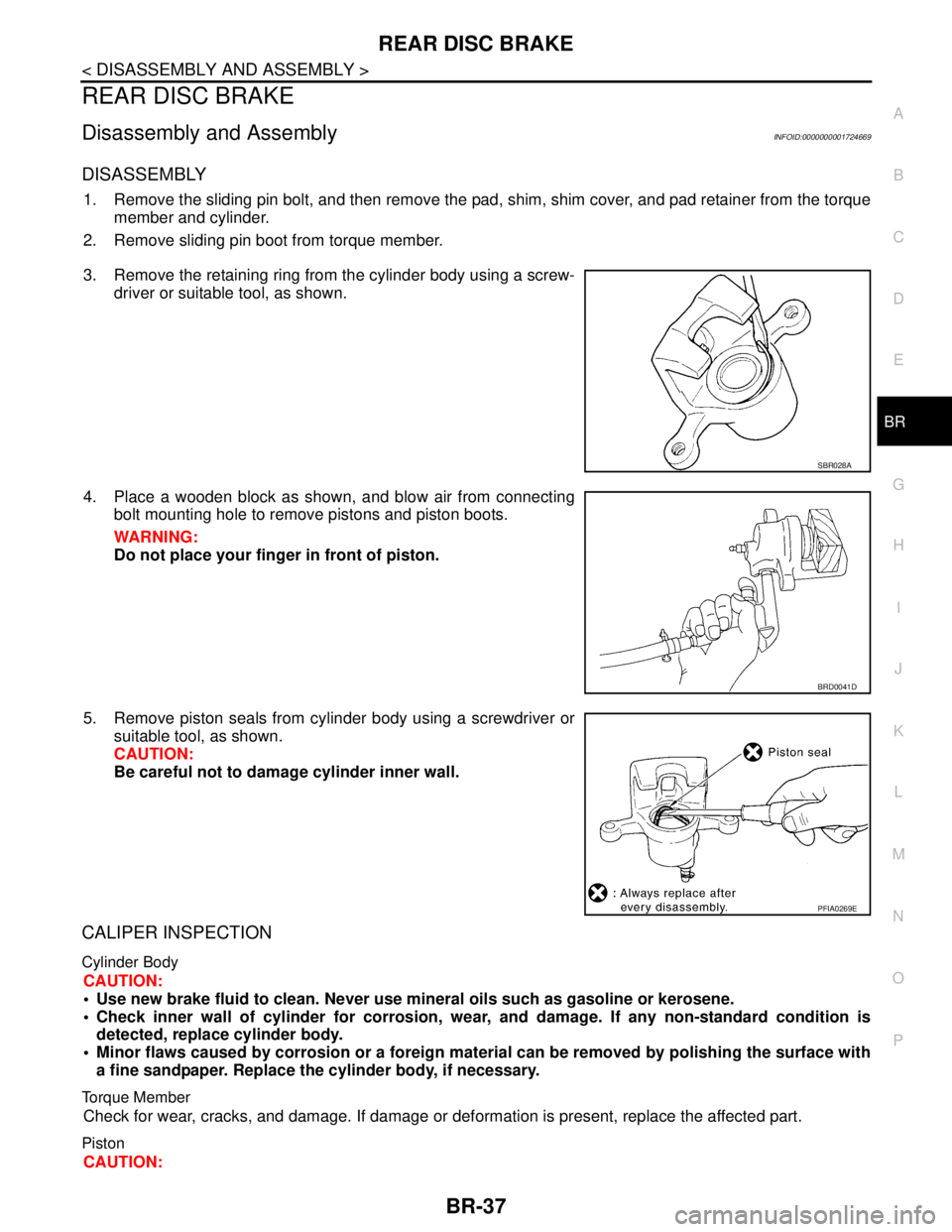
3. Remove the retaining ring from the cylinder body using a screw-
driver or suitable tool, as shown.
4. Place a wooden block as shown, and blow air from connecting
bolt mounting hole to remove pistons and piston boots.
WARNING:
Do not place your finger in front of piston.
5. Remove piston seals from cylinder body using a screwdriver or
suitable tool, as shown.
CAUTION:
Be careful not to damage cylinder inner wall.
CALIPER INSPECTION
Cylinder Body
CAUTION:
Use new brake fluid to clean. Never use mineral oils such as gasoline or kerosene.
Check inner wall of cylinder for corrosion, wear, and damage. If any non-standard condition is
detected, replace cylinder body.
Minor flaws caused by corrosion or a foreign material can be removed by polishing the surface with
a fine sandpaper. Replace the cylinder body, if necessary.
Torque Member
Check for wear, cracks, and damage. If damage or deformation is present, replace the affected part.
Piston
CAUTION:
SBR028A
BRD0041D
PFIA0269E
Page 263 of 5883
![NISSAN TIIDA 2007 Service Repair Manual BRC-30
< COMPONENT DIAGNOSIS >[ABS]
C1101, C1102, C1103, C1104 WHEEL SENSOR-1
COMPONENT DIAGNOSIS
C1101, C1102, C1103, C1104 WHEEL SENSOR-1
DescriptionINFOID:0000000001731225
When the sensor rotor rot NISSAN TIIDA 2007 Service Repair Manual BRC-30
< COMPONENT DIAGNOSIS >[ABS]
C1101, C1102, C1103, C1104 WHEEL SENSOR-1
COMPONENT DIAGNOSIS
C1101, C1102, C1103, C1104 WHEEL SENSOR-1
DescriptionINFOID:0000000001731225
When the sensor rotor rot](/manual-img/5/57395/w960_57395-262.png)
BRC-30
< COMPONENT DIAGNOSIS >[ABS]
C1101, C1102, C1103, C1104 WHEEL SENSOR-1
COMPONENT DIAGNOSIS
C1101, C1102, C1103, C1104 WHEEL SENSOR-1
DescriptionINFOID:0000000001731225
When the sensor rotor rotates, the magnetic field changes. It converts the magnetic field changes to current
signals (rectangular wave) and transmits them to the ABS actuator and electric unit (control unit).
DTC LogicINFOID:0000000001731226
DTC DETECTION LOGIC
DTC CONFIRMATION PROCEDURE
1.CHECK SELF-DIAGNOSIS RESULTS
Check the self-diagnosis results.
Is above displayed on the self-diagnosis display?
YES >> Proceed to diagnosis procedure. Refer to BRC-30, "Diagnosis Procedure".
NO >> INSPECTION END
Diagnosis ProcedureINFOID:0000000001731227
CAUTION:
Do not check between wheel sensor terminals.
INSPECTION PROCEDURE
1.CONNECTOR INSPECTION
Disconnect the ABS actuator and electric unit (control unit) connector E125 and wheel sensor of malfunction-
ing code.
Check the terminals for deformation, disconnection, looseness or damage.
Is the inspection result normal?
YES >> GO TO 2
NO >> Repair or replace as necessary.
2.CHECK WHEEL SENSOR OUTPUT SIGNAL
1. Connect ABS active wheel sensor tester (J-45741) to wheel sensor using appropriate adapter.
2. Turn on the ABS active wheel sensor tester power switch.
NOTE:
The green POWER indicator should illuminate. If the POWER indicator does not illuminate, replace the
battery in the ABS active wheel sensor tester before proceeding.
DTC Display item Malfunction detected condition Possible cause
C1101 RR RH SENSOR-1Circuit of rear RH wheel sensor is open. Or when the sen-
sor power voltage is outside the standard.
Harness or connector
Wheel sensor
ABS actuator and electric unit
(control unit) C1102 RR LH SENSOR-1Circuit of rear LH wheel sensor is open. Or when the sen-
sor power voltage is outside the standard.
C1103 FR RH SENSOR-1Circuit of front RH wheel sensor is open. Or when the
sensor power voltage is outside the standard.
C1104 FR LH SENSOR-1Circuit of front LH wheel sensor is open. Or when the
sensor power voltage is outside the standard.
Self-diagnosis results
RR RH SENSOR-1
RR LH SENSOR-1
FR RH SENSOR-1
FR LH SENSOR-1
Page 266 of 5883
![NISSAN TIIDA 2007 Service Repair Manual C1105, C1106, C1107, C1108 WHEEL SENSOR-2
BRC-33
< COMPONENT DIAGNOSIS >[ABS]
C
D
E
G
H
I
J
K
L
MA
B
BRC
N
O
P
C1105, C1106, C1107, C1108 WHEEL SENSOR-2
DescriptionINFOID:0000000001731230
When the sen NISSAN TIIDA 2007 Service Repair Manual C1105, C1106, C1107, C1108 WHEEL SENSOR-2
BRC-33
< COMPONENT DIAGNOSIS >[ABS]
C
D
E
G
H
I
J
K
L
MA
B
BRC
N
O
P
C1105, C1106, C1107, C1108 WHEEL SENSOR-2
DescriptionINFOID:0000000001731230
When the sen](/manual-img/5/57395/w960_57395-265.png)
C1105, C1106, C1107, C1108 WHEEL SENSOR-2
BRC-33
< COMPONENT DIAGNOSIS >[ABS]
C
D
E
G
H
I
J
K
L
MA
B
BRC
N
O
P
C1105, C1106, C1107, C1108 WHEEL SENSOR-2
DescriptionINFOID:0000000001731230
When the sensor rotor rotates, the magnetic field changes. It converts the magnetic field changes to current
signals (rectangular wave) and transmits them to the ABS actuator and electric unit (control unit).
DTC LogicINFOID:0000000001731231
DTC DETECTION LOGIC
DTC CONFIRMATION PROCEDURE
1.CHECK SELF-DIAGNOSIS RESULTS
Check the self-diagnosis results.
Is above displayed on the self-diagnosis display?
YES >> Proceed to diagnosis procedure. Refer to BRC-33, "Diagnosis Procedure".
NO >> INSPECTION END
Diagnosis ProcedureINFOID:0000000001731232
CAUTION:
Do not check between wheel sensor terminals.
INSPECTION PROCEDURE
1.CONNECTOR INSPECTION
Disconnect the ABS actuator and electric unit (control unit) connector E125 and wheel sensor of malfunction-
ing code.
Check the terminals for deformation, disconnection, looseness or damage.
Is the inspection result normal?
YES >> GO TO 2
NO >> Repair or replace as necessary.
DTC Display item Malfunction detected condition Possible cause
C1105 RR RH SENSOR-2When the circuit in the rear RH wheel sensor is short-cir-
cuited. Or when the distance between the wheel sensor
and sensor rotor is too large and the sensor pulse cannot
be recognized by the control unit.
Harness or connector
Wheel sensor
ABS actuator and electric unit
(control unit) C1106 RR LH SENSOR-2When the circuit in the rear LH wheel sensor is short-cir-
cuited. Or when the distance between the wheel sensor
and sensor rotor is too large and the sensor pulse cannot
be recognized by the control unit.
C1107 FR RH SENSOR-2When the circuit in the front RH wheel sensor is short-cir-
cuited. Or when the distance between the wheel sensor
and sensor rotor is too large and the sensor pulse cannot
be recognized by the control unit.
C1108 FR LH SENSOR-2When the circuit in the front LH wheel sensor is short-cir-
cuited. Or when the distance between the wheel sensor
and sensor rotor is too large and the sensor pulse cannot
be recognized by the control unit.
Self-diagnosis results
RR RH SENSOR-2
RR LH SENSOR-2
FR RH SENSOR-2
FR LH SENSOR-2
Page 269 of 5883
![NISSAN TIIDA 2007 Service Repair Manual BRC-36
< COMPONENT DIAGNOSIS >[ABS]
C1109 POWER AND GROUND SYSTEM
C1109 POWER AND GROUND SYSTEM
DescriptionINFOID:0000000001731235
Supplies electric power to the ABS actuator and electric unit (contro NISSAN TIIDA 2007 Service Repair Manual BRC-36
< COMPONENT DIAGNOSIS >[ABS]
C1109 POWER AND GROUND SYSTEM
C1109 POWER AND GROUND SYSTEM
DescriptionINFOID:0000000001731235
Supplies electric power to the ABS actuator and electric unit (contro](/manual-img/5/57395/w960_57395-268.png)
BRC-36
< COMPONENT DIAGNOSIS >[ABS]
C1109 POWER AND GROUND SYSTEM
C1109 POWER AND GROUND SYSTEM
DescriptionINFOID:0000000001731235
Supplies electric power to the ABS actuator and electric unit (control unit).
DTC LogicINFOID:0000000001731236
DTC DETECTION LOGIC
DTC CONFIRMATION PROCEDURE
1.CHECK SELF-DIAGNOSIS RESULTS
Check the self-diagnosis results.
Is above displayed on the self-diagnosis display?
YES >> Proceed to diagnosis procedure. Refer to BRC-36, "Diagnosis Procedure".
NO >> INSPECTION END
Diagnosis ProcedureINFOID:0000000001731237
INSPECTION PROCEDURE
1.CHECK CONNECTOR
1. Turn ignition switch OFF.
2. Disconnect ABS actuator and electric unit (control unit) connector.
3. Check terminal for deformation, disconnection, looseness, and so on. If any malfunction is found, repair or
replace terminal.
4. Reconnect connectors and then perform the self-diagnosis. Refer to BRC-25, "
CONSULT-III Function
(ABS)".
Is any item indicated on the self-diagnosis display?
YES >> GO TO 2
NO >> Poor connection of connector terminal. Repair or replace connector.
2.CHECK ABS ACTUATOR AND ELECTRIC UNIT (CONTROL UNIT) POWER SUPPLY CIRCUIT AND
GROUND CIRCUIT
1. Turn ignition switch OFF.
2. Disconnect ABS actuator and electric unit (control unit) connector.
3. Turn ignition switch ON or OFF and check voltage between ABS
actuator and electric unit (control unit) harness connector termi-
nal and ground.
4. Turn ignition switch OFF.
DTC Display item Malfunction detected condition Possible cause
C1109BATTERY VOLTAGE
[ABNORMAL]When the ABS actuator and electric unit (control unit)
power supply voltage is lower than normal. Harness or connector
ABS actuator and electric unit
(control unit)
Self-diagnosis results
BATTERY VOLTAGE [ABNORMAL]
ABS actuator and elec-
tric unit (control unit)
— Condition Voltage
Connector Terminal
E125 4 GroundIgnition switch: ON Battery voltage
Ignition switch: OFF Approx. 0V
AWFIA0015ZZ