2007 NISSAN TIIDA wiring
[x] Cancel search: wiringPage 4309 of 5883

MWI-2
IPDM E/R (INTELLIGENT POWER DISTRIBU-
TION MODULE ENGINE ROOM) : Diagnosis Pro-
cedure .....................................................................
27
FUEL LEVEL SENSOR SIGNAL CIRCUIT .......29
Description ..............................................................29
Component Function Check ...................................29
Diagnosis Procedure .............................................29
Component Inspection ............................................30
OIL PRESSURE SWITCH SIGNAL CIRCUIT ...31
Description ..............................................................31
Component Function Check ...................................31
Diagnosis Procedure ..............................................31
Component Inspection ............................................31
OIL LEVEL SENSOR SIGNAL CIRCUIT ..........32
Description ..............................................................32
Diagnosis Procedure (With Diesel) .........................32
Diagnosis Procedure (Without Diesel) ....................32
Component Inspection (With Diesel) ......................32
Component Inspection (Without Diesel) .................33
AMBIENT SENSOR SIGNAL CIRCUIT .............34
Description ..............................................................34
Diagnosis Procedure ..............................................34
Component Inspection ............................................35
ECU DIAGNOSIS ........................................36
COMBINATION METER ....................................36
Reference Value .....................................................36
Wiring Diagram .......................................................39
Fail Safe .................................................................53
DTC Index ..............................................................54
BCM (BODY CONTROL MODULE) ..................55
Reference Value .....................................................55
Terminal Layout ......................................................58
Physical Values ......................................................58
Wiring Diagram .......................................................70
DTC Inspection Priority Chart ..............................73
DTC Index ..............................................................74
IPDM E/R (INTELLIGENT POWER DISTRI-
BUTION MODULE ENGINE ROOM) .................
75
Reference Value .....................................................75
Terminal Layout ......................................................77
Physical Values ......................................................77
Wiring Diagram .......................................................81
Fail Safe .................................................................84
DTC Index ..............................................................86
SYMPTOM DIAGNOSIS ............................87
THE FUEL GAUGE POINTER DOES NOT
MOVE .................................................................
87
Description ..............................................................87
Diagnosis Procedure ...............................................87
THE FUEL GAUGE POINTER DOES NOT
MOVE TO "F" WHEN REFUELING ..................
88
Description ..............................................................88
Diagnosis Procedure ...............................................88
THE OIL PRESSURE WARNING LAMP
DOES NOT TURN ON .......................................
89
Description ..............................................................89
Diagnosis Procedure ...............................................89
THE OIL PRESSURE WARNING LAMP
DOES NOT TURN OFF .....................................
90
Description ..............................................................90
Diagnosis Procedure ...............................................90
THE AMBIENT TEMPERATURE DISPLAY IS
INCORRECT ......................................................
91
Description ..............................................................91
Diagnosis Procedure ...............................................91
NORMAL OPERATING CONDITION ................92
INFORMATION DISPLAY .........................................92
INFORMATION DISPLAY : Description ..................92
PRECAUTION ............................................93
PRECAUTIONS .................................................93
Supplemental Restraint System (SRS) "AIR BAG"
and "SEAT BELT PRE-TENSIONER" ....................
93
ON-VEHICLE REPAIR ...............................94
COMBINATION METER ....................................94
Removal and Installation .........................................94
DISASSEMBLY AND ASSEMBLY ............97
COMBINATION METER ....................................97
Disassembly and Assembly ....................................97
Page 4346 of 5883

MWI
COMBINATION METER
MWI-39
< ECU DIAGNOSIS >
C
D
E
F
G
H
I
J
K
L
MB A
O
P
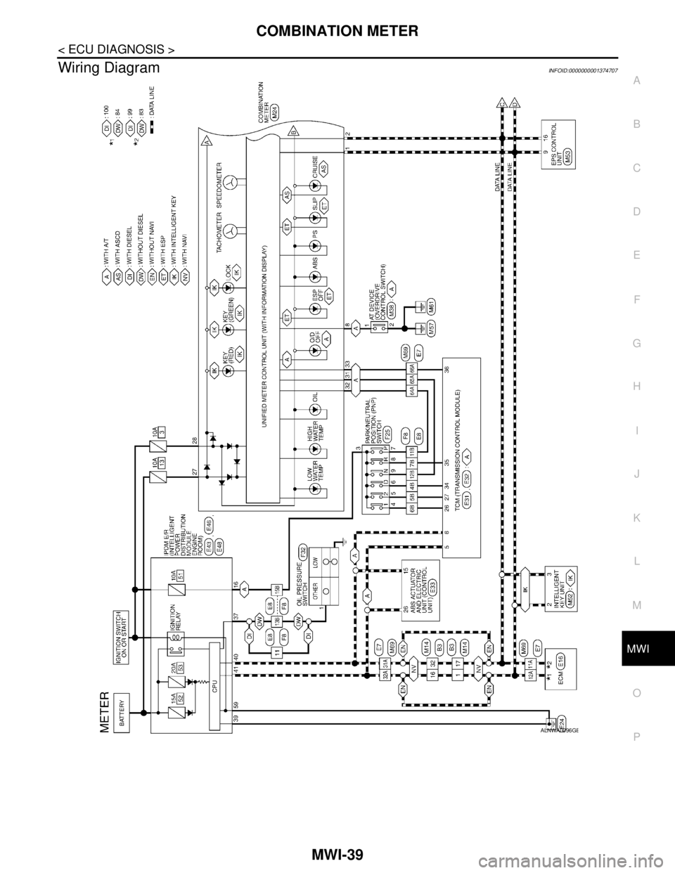
Wiring DiagramINFOID:0000000001374707
ALNWA0096GB
Page 4377 of 5883

MWI-70
< ECU DIAGNOSIS >
BCM (BODY CONTROL MODULE)
Wiring Diagram
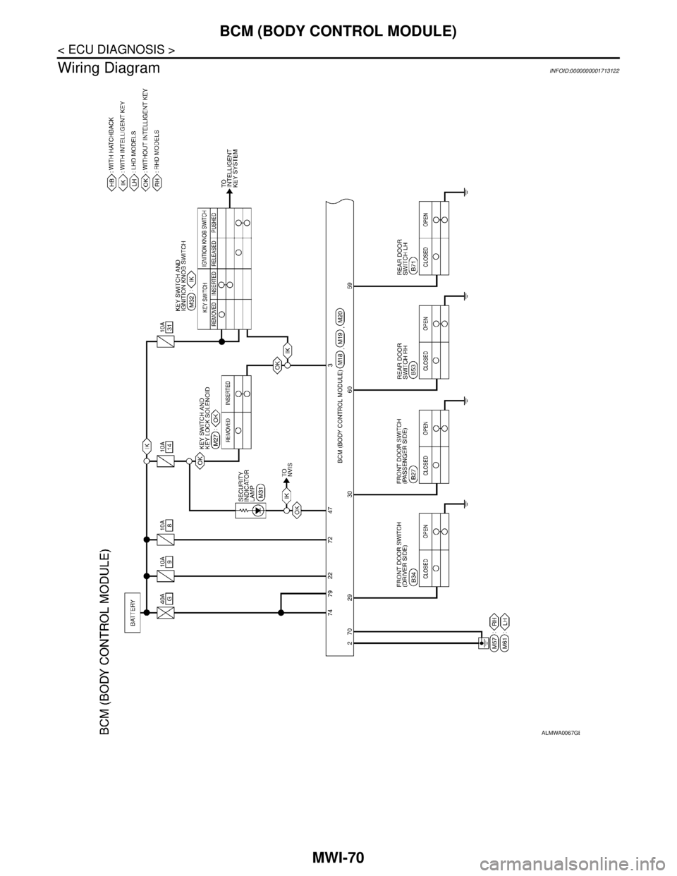
INFOID:0000000001713122
ALMWA0067GB
Page 4388 of 5883

MWI
IPDM E/R (INTELLIGENT POWER DISTRIBUTION MODULE ENGINE ROOM)
MWI-81
< ECU DIAGNOSIS >
C
D
E
F
G
H
I
J
K
L
MB A
O
P
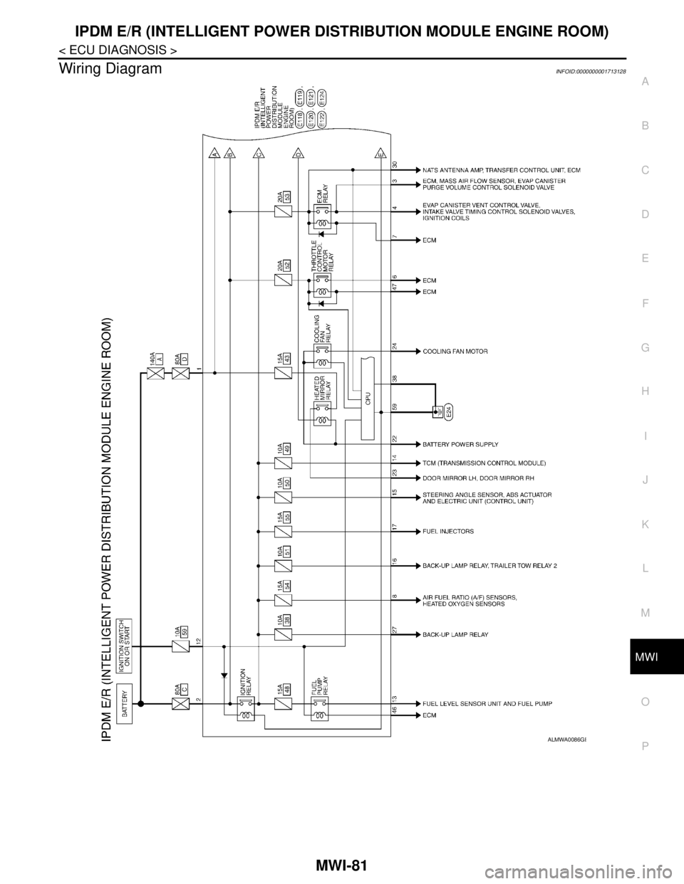
Wiring DiagramINFOID:0000000001713128
ALMWA0086GB
Page 4400 of 5883

MWI
PRECAUTIONS
MWI-93
< PRECAUTION >
C
D
E
F
G
H
I
J
K
L
MB A
O
P
PRECAUTION
PRECAUTIONS
Supplemental Restraint System (SRS) "AIR BAG" and "SEAT BELT PRE-TENSION-
ER"
INFOID:0000000001374731
The Supplemental Restraint System such as “AIR BAG” and “SEAT BELT PRE-TENSIONER”, used along
with a front seat belt, helps to reduce the risk or severity of injury to the driver and front passenger for certain
types of collision. Information necessary to service the system safely is included in the SR and SB section of
this Service Manual.
WARNING:
To avoid rendering the SRS inoperative, which could increase the risk of personal injury or death in
the event of a collision which would result in air bag inflation, all maintenance must be performed by
an authorized NISSAN/INFINITI dealer.
Improper maintenance, including incorrect removal and installation of the SRS, can lead to personal
injury caused by unintentional activation of the system. For removal of Spiral Cable and Air Bag
Module, see the SR section.
Do not use electrical test equipment on any circuit related to the SRS unless instructed to in this
Service Manual. SRS wiring harnesses can be identified by yellow and/or orange harnesses or har-
ness connectors.
Page 4406 of 5883

PB-2
< PRECAUTION >
PRECAUTIONS
PRECAUTION
PRECAUTIONS
Precaution for Supplemental Restraint System (SRS) "AIR BAG" and "SEAT BELT
PRE-TENSIONER"
INFOID:0000000001716772
The Supplemental Restraint System such as “AIR BAG” and “SEAT BELT PRE-TENSIONER”, used along
with a front seat belt, helps to reduce the risk or severity of injury to the driver and front passenger for certain
types of collision. This system includes seat belt switch inputs and dual stage front air bag modules. The SRS
system uses the seat belt switches to determine the front air bag deployment, and may only deploy one front
air bag, depending on the severity of a collision and whether the front occupants are belted or unbelted.
Information necessary to service the system safely is included in the SR and SB section of this Service Man-
ual.
WARNING:
• To avoid rendering the SRS inoperative, which could increase the risk of personal injury or death in
the event of a collision which would result in air bag inflation, all maintenance must be performed by
an authorized NISSAN/INFINITI dealer.
Improper maintenance, including incorrect removal and installation of the SRS, can lead to personal
injury caused by unintentional activation of the system. For removal of Spiral Cable and Air Bag
Module, see the SR section.
Do not use electrical test equipment on any circuit related to the SRS unless instructed to in this
Service Manual. SRS wiring harnesses can be identified by yellow and/or orange harnesses or har-
ness connectors.
Page 4415 of 5883

PCS
PCS-1
ELECTRICAL & POWER CONTROL
C
D
E
F
G
H
I
J
K
L B
SECTION PCS
A
O
P N
CONTENTS
POWER CONTROL SYSTEM
IPDM E/R
FUNCTION DIAGNOSIS ...............................
3
RELAY CONTROL SYSTEM ..............................3
System Diagram ........................................................3
System Description ...................................................4
Component Parts Location ........................................5
POWER CONTROL SYSTEM .............................6
System Diagram ........................................................6
System Description ...................................................6
SIGNAL BUFFER SYSTEM ................................7
System Diagram ........................................................7
System Description ...................................................7
POWER CONSUMPTION CONTROL SYS-
TEM .....................................................................
8
System Diagram ........................................................8
System Description ...................................................8
Component Parts Location ........................................9
DIAGNOSIS SYSTEM (IPDM E/R) .....................10
Diagnosis Description .............................................10
CONSULT - III Function (IPDM E/R) .......................13
COMPONENT DIAGNOSIS .........................15
U1000 CAN COMM CIRCUIT .............................15
Description ..............................................................15
DTC Logic ...............................................................15
Diagnosis Procedure ...............................................15
POWER SUPPLY AND GROUND CIRCUIT ......16
Diagnosis Procedure ...............................................16
ECU DIAGNOSIS .........................................17
IPDM E/R (INTELLIGENT POWER DISTRI-
BUTION MODULE ENGINE ROOM) .................
17
Reference Value .....................................................17
Terminal Layout ......................................................19
Physical Values .......................................................19
Wiring Diagram ........................................................23
Fail Safe ..................................................................26
DTC Index ...............................................................28
PRECAUTION ..............................................29
PRECAUTIONS .................................................29
Precaution for Supplemental Restraint System
(SRS) "AIR BAG" and "SEAT BELT PRE-TEN-
SIONER" .................................................................
29
REMOVAL AND INSTALLATION ...............30
IPDM E/R (INTELLIGENT POWER DISTRI-
BUTION MODULE ENGINE ROOM) ................
30
Removal and Installation of IPDM E/R ....................30
POWER DISTRIBUTION SYSTEM
BASIC INSPECTION ...................................
31
DIAGNOSIS AND REPAIR WORKFLOW ........31
Work Flow ................................................................31
FUNCTION DIAGNOSIS ..............................34
POWER DISTRIBUTION SYSTEM ...................34
System Description ..................................................34
Component Parts Location ......................................34
Component Description ..........................................34
DIAGNOSIS SYSTEM (BCM) ...........................35
COMMON ITEM .........................................................35
COMMON ITEM : Diagnosis Description ................35
COMMON ITEM : CONSULT-III Function ...............35
INTELLIGENT KEY ....................................................35
INTELLIGENT KEY : CONSULT-III Function
(BCM - INTELLIGENT KEY) ....................................
35
COMPONENT DIAGNOSIS .........................36
Page 4416 of 5883

PCS-2
U1000 CAN COMM CIRCUIT ............................36
Description ..............................................................36
DTC Logic ...............................................................36
Diagnosis Procedure ..............................................36
POWER SUPPLY AND GROUND CIRCUIT .....37
BCM ...........................................................................37
BCM : Diagnosis Procedure ...................................37
BCM : Special Repair Requirement ........................37
IPDM E/R (INTELLIGENT POWER DISTRIBU-
TION MODULE ENGINE ROOM) .............................
37
IPDM E/R (INTELLIGENT POWER DISTRIBU-
TION MODULE ENGINE ROOM) : Diagnosis Pro-
cedure .....................................................................
37
ECU DIAGNOSIS ........................................38
BCM (BODY CONTROL MODULE) ..................38
Reference Value .....................................................38
Terminal Layout ......................................................38
Physical Values ......................................................38
Wiring Diagram .......................................................38
DTC Inspection Priority Chart ...............................38
DTC Index ..............................................................38
IPDM E/R (INTELLIGENT POWER DISTRI-
BUTION MODULE ENGINE ROOM) .................
39
Reference Value .....................................................39
Terminal Layout ......................................................39
Physical Values .......................................................39
Wiring Diagram .......................................................39
Fail Safe .................................................................39
DTC Index ..............................................................39
ON-VEHICLE MAINTENANCE ..................40
PRE-INSPECTION FOR DIAGNOSTIC ............40
Basic Inspection ......................................................40
ON-VEHICLE REPAIR ...............................41
BCM (BODY CONTROL MODULE) ..................41
Removal and Installation .........................................41