2007 NISSAN TIIDA wiring
[x] Cancel search: wiringPage 3650 of 5883
HORN
HRN-3
< COMPONENT DIAGNOSIS >
C
D
E
F
G
H
I
J
K
MA
B
HRN
N
O
P
COMPONENT DIAGNOSIS
HORN
Wiring DiagramINFOID:0000000001702207
AWMWA0025GB
Page 3652 of 5883
INL-1
DRIVER CONTROLS
C
D
E
F
G
H
I
J
K
M
SECTION INL
A
B
INL
N
O
P
CONTENTS
INTERIOR LIGHTING SYSTEM
BASIC INSPECTION ....................................2
DIAGNOSIS AND REPAIR WORKFLOW ..........2
Work Flow .................................................................2
FUNCTION DIAGNOSIS ...............................5
INTERIOR ROOM LAMP CONTROL SYSTEM
.....
5
System Diagram ........................................................5
System Description ...................................................5
Component Parts Location ........................................6
Component Description ............................................6
ILLUMINATION CONTROL SYSTEM .................8
System Diagram ........................................................8
System Description ...................................................8
Component Parts Location ........................................8
Component Description .............................................9
DIAGNOSIS SYSTEM (BCM) ............................10
COMMON ITEM .........................................................10
COMMON ITEM : CONSULT-III Function (BCM -
COMMON ITEM) .....................................................
10
INT LAMP ..................................................................10
INT LAMP : CONSULT-III Function (BCM - INT
LAMP) .....................................................................
10
BATTERY SAVER .....................................................12
BATTERY SAVER : CONSULT-III Function (BCM
- BATTERY SAVER) ...............................................
12
COMPONENT DIAGNOSIS .........................14
POWER SUPPLY AND GROUND CIRCUIT ......14
BCM ...........................................................................14
BCM : Diagnosis Procedure ....................................14
INTERIOR ROOM LAMP POWER SUPPLY
CIRCUIT ............................................................
15
Description ...............................................................15
Component Function Check ....................................15
Diagnosis Procedure ...............................................15
INTERIOR ROOM LAMP CONTROL SYSTEM
...
17
Wiring Diagram - INTERIOR ROOM LAMP - ..........17
ILLUMINATION .................................................20
Wiring Diagram - ILLUMINATION - .........................20
ECU DIAGNOSIS .........................................22
BCM (BODY CONTROL MODULE) .................22
Description ...............................................................22
SYMPTOM DIAGNOSIS ..............................23
INTERIOR LIGHTING SYSTEM SYMPTOMS ...23
Symptom Table .......................................................23
PRECAUTION ..............................................24
PRECAUTIONS .................................................24
Supplemental Restraint System (SRS) "AIR BAG"
and "SEAT BELT PRE-TENSIONER" .....................
24
General precautions for service operations .............24
ON-VEHICLE REPAIR .................................25
INTERIOR ROOM LAMP ..................................25
Removal and Installation .........................................25
SERVICE DATA AND SPECIFICATIONS
(SDS) ............................................................
28
SERVICE DATA AND SPECIFICATIONS
(SDS) .................................................................
28
Bulb Specifications ..................................................28
Page 3668 of 5883
INTERIOR ROOM LAMP CONTROL SYSTEM
INL-17
< COMPONENT DIAGNOSIS >
C
D
E
F
G
H
I
J
K
MA
B
INL
N
O
P
INTERIOR ROOM LAMP CONTROL SYSTEM
Wiring Diagram - INTERIOR ROOM LAMP -INFOID:0000000001728876
ALLWA0124GB
Page 3671 of 5883
INL-20
< COMPONENT DIAGNOSIS >
ILLUMINATION
ILLUMINATION
Wiring Diagram - ILLUMINATION -INFOID:0000000001728877
ALLWA0122GB
Page 3673 of 5883
INL-22
< ECU DIAGNOSIS >
BCM (BODY CONTROL MODULE)
ECU DIAGNOSIS
BCM (BODY CONTROL MODULE)
DescriptionINFOID:0000000001730971
REFERENCE VALUES FOR BCM
For BCM reference values, refer to XX-XX, "*****".
TERMINAL LAYOUT FOR BCM
For the terminal layout for the BCM, refer to XX-XX, "*****".
PHYSICAL VALUES FOR BCM
For physical values for the BCM, refer to XX-XX, "*****".
WIRING DIAGRAM - BCM
For the BCM wiring diagram, refer to XX-XX, "*****".
DTC INSPECTION PRIORITY CHART - BCM
For the BCM DTC inspection priority chart, refer to XX-XX, "*****".
DTC INDEX - BCM
For the BCM DTC index, refer to XX-XX, "*****".
Page 3675 of 5883
INL-24
< PRECAUTION >
PRECAUTIONS
PRECAUTION
PRECAUTIONS
Supplemental Restraint System (SRS) "AIR BAG" and "SEAT BELT PRE-TENSION-
ER"
INFOID:0000000001726696
The Supplemental Restraint System such as “AIR BAG” and “SEAT BELT PRE-TENSIONER”, used along
with a front seat belt, helps to reduce the risk or severity of injury to the driver and front passenger for certain
types of collision. Information necessary to service the system safely is included in the SR and SB section of
this Service Manual.
Information necessary to service the system safely is included in the SR and SB section of this Service Man-
ual.
WARNING:
• To avoid rendering the SRS inoperative, which could increase the risk of personal injury or death in
the event of a collision which would result in air bag inflation, all maintenance must be performed by
an authorized NISSAN/INFINITI dealer.
Improper maintenance, including incorrect removal and installation of the SRS, can lead to personal
injury caused by unintentional activation of the system. For removal of Spiral Cable and Air Bag
Module, see the SR section.
Do not use electrical test equipment on any circuit related to the SRS unless instructed to in this
Service Manual. SRS wiring harnesses can be identified by yellow and/or orange harnesses or har-
ness connectors.
General precautions for service operationsINFOID:0000000001726697
When removing or disassembling any part, be careful not to damage or deform it. Protect parts which may
get in the way with cloth.
When removing parts with a screw driver or other tool, protect parts by wrapping them with vinyl or tape.
Keep removed parts protected with cloth.
If an non-reuseable part is removed, replace it with a new one.
After re-assembly has been completed, make sure each part functions correctly.
Never work with wet hands.
Turn the lighting switch OFF before disconnecting and connecting the connector.
Do not use organic solvent (paint thinner or gasoline) to clean lamps or remove sealant residue.
Page 3681 of 5883
INT-2
< PRECAUTION >
PRECAUTIONS
PRECAUTION
PRECAUTIONS
Precaution for Supplemental Restraint System (SRS) "AIR BAG" and "SEAT BELT
PRE-TENSIONER"
INFOID:0000000001530009
The Supplemental Restraint System such as “AIR BAG” and “SEAT BELT PRE-TENSIONER”, used along
with a front seat belt, helps to reduce the risk or severity of injury to the driver and front passenger for certain
types of collision. Information necessary to service the system safely is included in the SR and SB section of
this Service Manual.
WARNING:
• To avoid rendering the SRS inoperative, which could increase the risk of personal injury or death in
the event of a collision which would result in air bag inflation, all maintenance must be performed by
an authorized NISSAN/INFINITI dealer.
Improper maintenance, including incorrect removal and installation of the SRS, can lead to personal
injury caused by unintentional activation of the system. For removal of Spiral Cable and Air Bag
Module, see the SR section.
Do not use electrical test equipment on any circuit related to the SRS unless instructed to in this
Service Manual. SRS wiring harnesses can be identified by yellow and/or orange harnesses or har-
ness connectors.
PrecautionINFOID:0000000001329036
When removing or disassembling any part, be careful not to damage or deform it. Protect parts which may
get in the way with cloth.
When removing parts with a screwdriver or other tool, protect parts by wrapping them with vinyl or tape.
Keep removed parts protected with cloth.
If a clip is deformed or damaged, replace it.
If an unreusable part is removed, replace it with a new one.
Tighten bolts and nuts firmly to the specified torque.
After re-assembly has been completed, make sure each part functions correctly.
Remove stains in the following way.
- Water-soluble stains:
Dip a cloth in warm water, and squeeze tightly. After wiping the stain, wipe with a soft dry cloth.
- Oil stain:
Dissolve a synthetic detergent in warm water (density of 2 to 3% or less), dip the cloth, then clean off the
stain with the cloth. Next, dip the soft cloth in fresh water, and then squeeze it tightly. Then clean off the
detergent completely. Then wipe the area with a soft dry cloth.
Do not use any organic solvent, such as thinner or benzine.
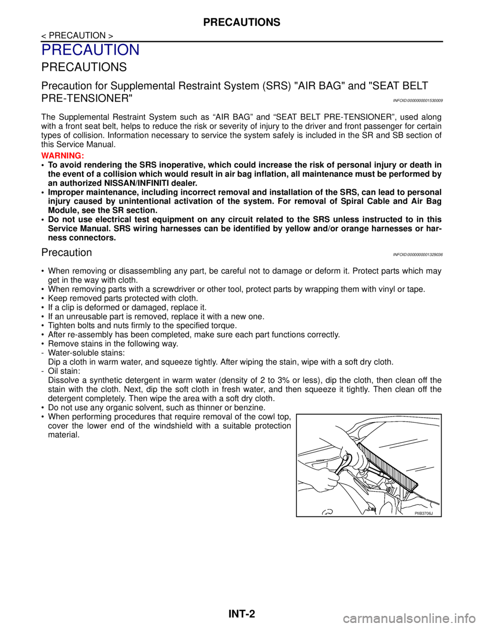
When performing procedures that require removal of the cowl top,
cover the lower end of the windshield with a suitable protection
material.
PIIB3706J
Page 3688 of 5883
SQUEAK AND RATTLE TROUBLE DIAGNOSIS
INT-9
< PREPARATION >
C
D
E
F
G
H
I
K
L
MA
B
INT
N
O
P
SILICONE GREASE
Used in place of UHMW tape that will be visible or not fit.
Note: Will only last a few months.
SILICONE SPRAY
Use when grease cannot be applied.
DUCT TAPE
Use to eliminate movement.
CONFIRM THE REPAIR
Confirm that the cause of a noise is repaired by test driving the vehicle. Operate the vehicle under the same
conditions as when the noise originally occurred. Refer to the notes on the Diagnostic Worksheet.
Generic Squeak and Rattle TroubleshootingINFOID:0000000001329047
Refer to Table of Contents for specific component removal and installation information.
INSTRUMENT PANEL
Most incidents are caused by contact and movement between:
1. The cluster lid A and instrument panel
2. Acrylic lens and combination meter housing
3. Instrument panel to front pillar garnish
4. Instrument panel to windshield
5. Instrument panel pins
6. Wiring harnesses behind the combination meter
7. A/C defroster duct and duct joint
These incidents can usually be located by tapping or moving the components to duplicate the noise or by
pressing on the components while driving to stop the noise. Most of these incidents can be repaired by apply-
ing felt cloth tape or silicone spray (in hard to reach areas). Urethane pads can be used to insulate wiring har-
ness.
CAUTION:
Do not use silicone spray to isolate a squeak or rattle. If you saturate the area with silicone, you will
not be able to recheck the repair.
CENTER CONSOLE
Components to pay attention to include:
1. Shifter assembly cover to finisher
2. A/C control unit and cluster lid C
3. Wiring harnesses behind audio and A/C control unit
The instrument panel repair and isolation procedures also apply to the center console.
DOORS
Pay attention to the:
1. Finisher and inner panel making a slapping noise
2. Inside handle escutcheon to door finisher
3. Wiring harnesses tapping
4. Door striker out of alignment causing a popping noise on starts and stops
Tapping or moving the components or pressing on them while driving to duplicate the conditions can isolate
many of these incidents. You can usually insulate the areas with felt cloth tape or insulator foam blocks from
the NISSAN Squeak and Rattle Kit (J-43980) to repair the noise.
TRUNK
Trunk noises are often caused by a loose jack or loose items put into the trunk by the owner.
In addition look for:
1. Trunk lid bumpers out of adjustment
2. Trunk lid striker out of adjustment
3. The trunk lid torsion bars knocking together
4. A loose license plate or bracket